Prior to the 18th century, the rudder on ships was steered with just a tiller – much like you see on smaller longboats or other craft. Sometime during the 18th century (there is some debate as to when) the tillers were rigged to a wheel – as in the cool illustration below:
The above illustration shows the rigging right below the deck beneath the wheel. However, prior to this iteration, the rigging was above the deck – spreading out to each side of the wheel. That was the case for Swan class British ships like the Pegasus. The most notable portion of this system is the ship’s wheel of course. The wheel that comes with the Peg kit is a photoetched set of pieces that assemble into a pretty decent looking wheel. However, I have used in the past (here on the Confederacy) a really nice boxwood wheel kit from Chuck’s Syren store.
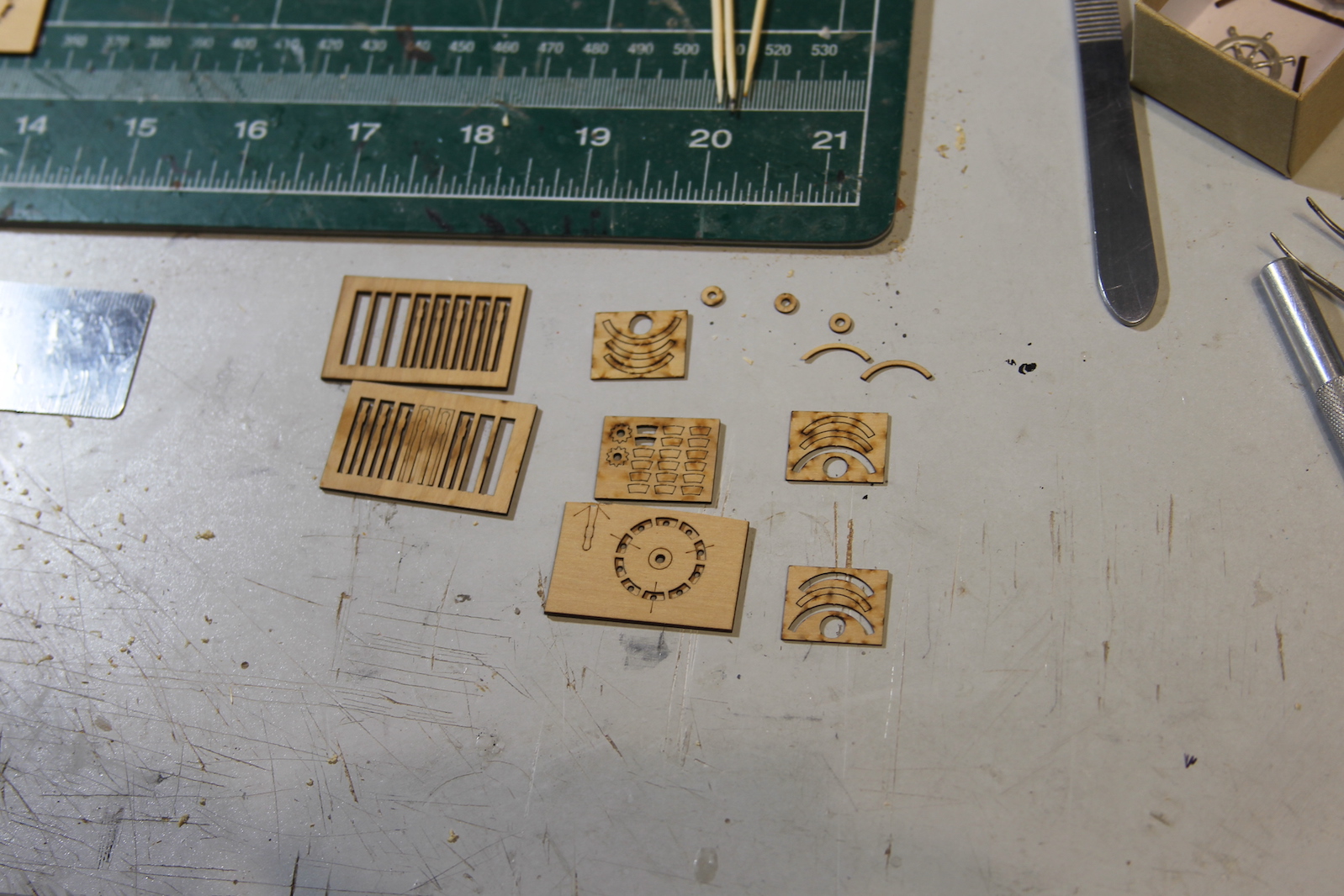
The kit comes with laser cut pieces that need to be shaped properly and a jig that facilitate putting them together. Every piece needs to be removed from its fitting and very lightly sanded to remove the black char around the edges. If this isn’t done it enhances the lines where the pieces are glued together and takes away from the realism.
First step is shaping all ten of the spokes. I accomplish this by sticking them in the Dremel chalk and using a combination of pin files and sanding sticks. The handle ends are tapered, but I’ve also tapered the base where the spoke goes into the hub to give them a little extra shape. Here’s were Chuck providing a couple extra spokes comes in handy – because these things snap off pretty easily if you’re not paying 100% attention the entire time. The spokes are trimmed, then glued into the hub using the above jig to keep them evenly spaced. The trick here is to use the tiniest amount of glue possible to hold the pieces together.


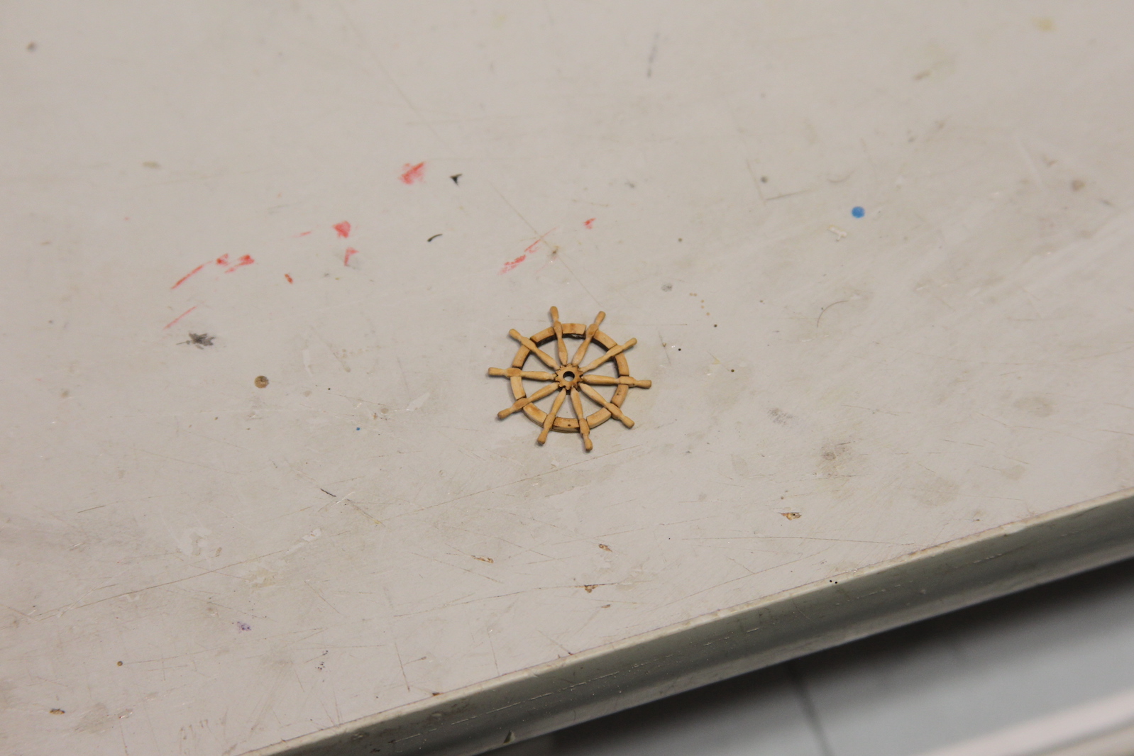
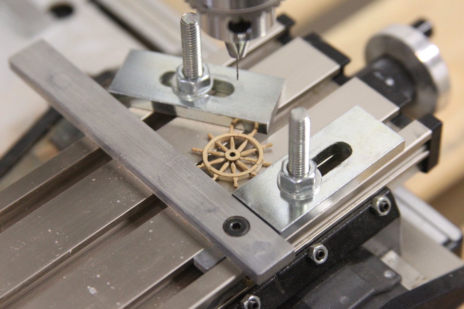
Next the outer rings are added. The kit provides three outer ring pieces, one of which is slightly larger than the others. However, the original wheels were build with more (and smaller) outer ring pieces – so I followed that route. Then outer ring is then sanded down until it is very thin – just enough to continue to hold all the pieces together. I added an additional detail of small treenails that hold the outer ring pieces together. Much like the deck treenails, these are simulated by drilling small holes then filling them in with glue and sawdust.
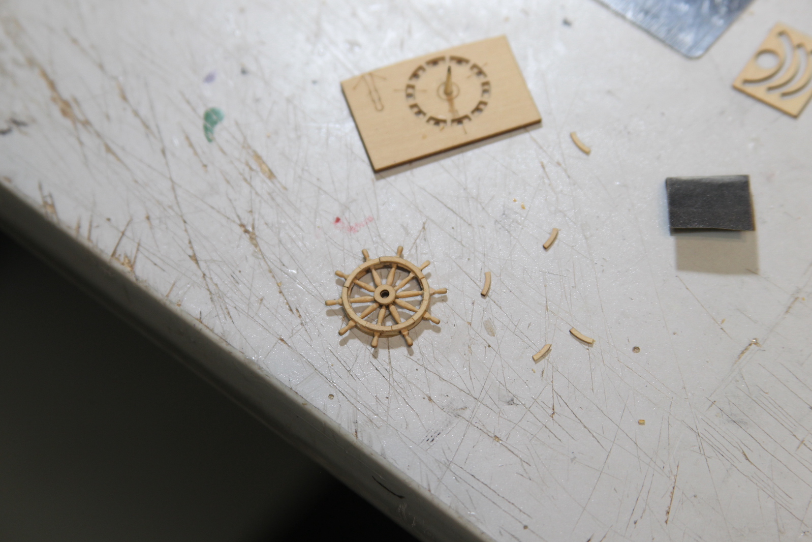
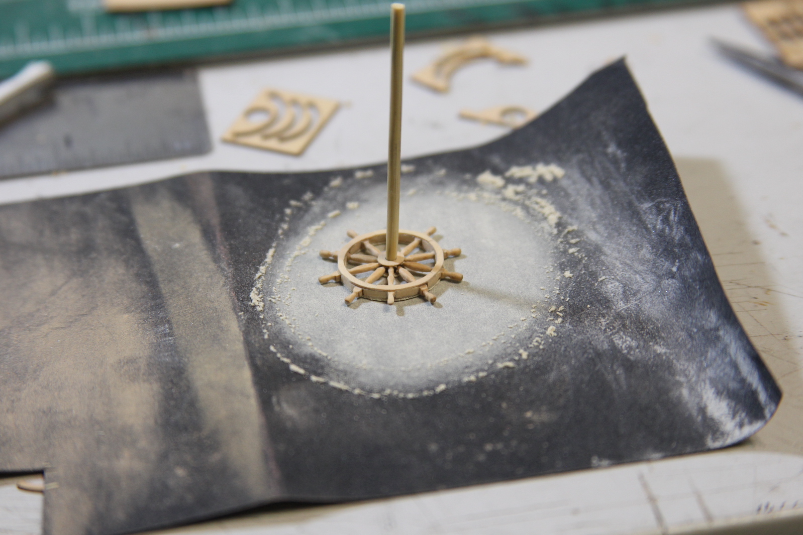
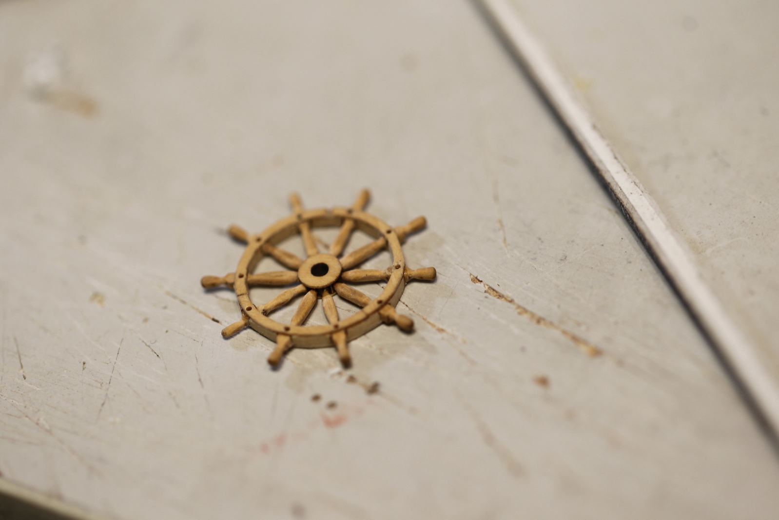
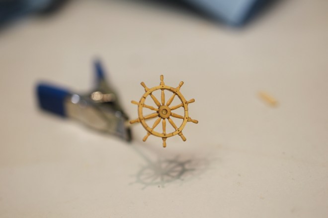
The entire wheel is then VERY gently sanded to even out all the pieces and remove any hard edges or misaligned parts.
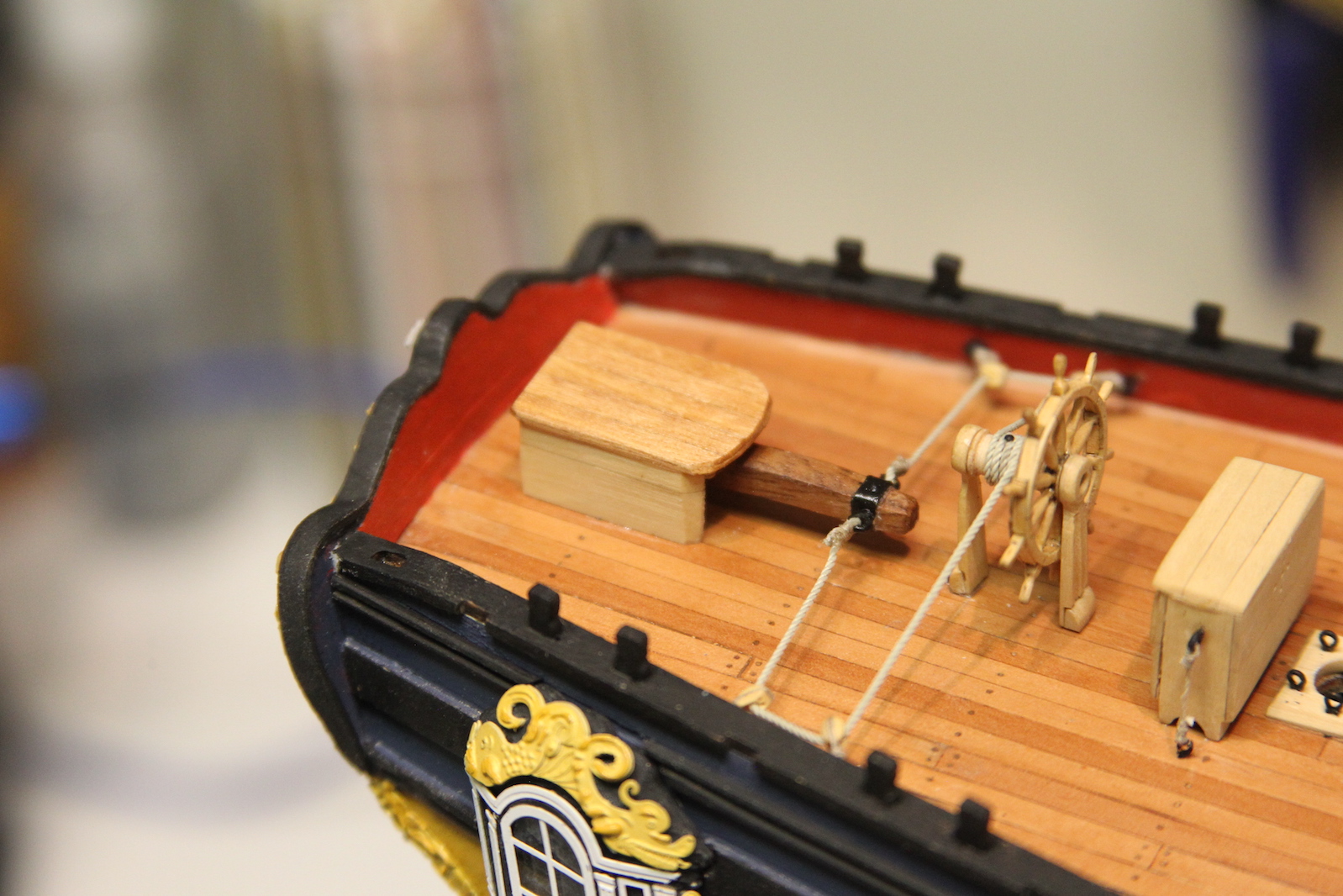
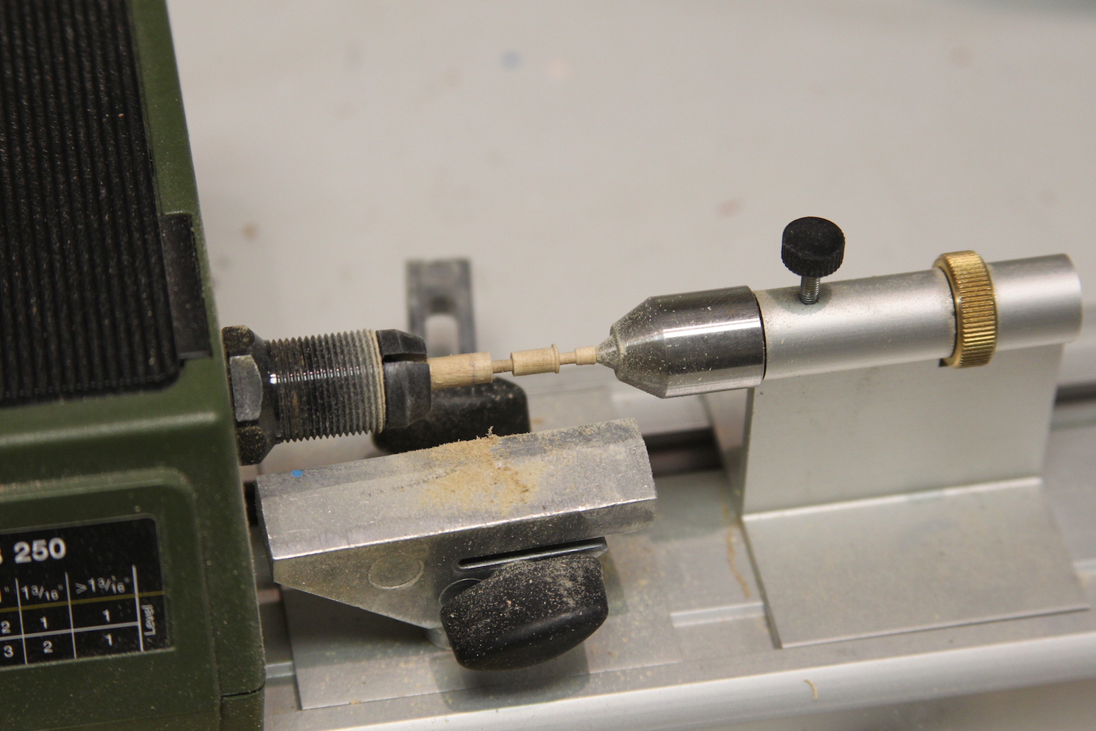
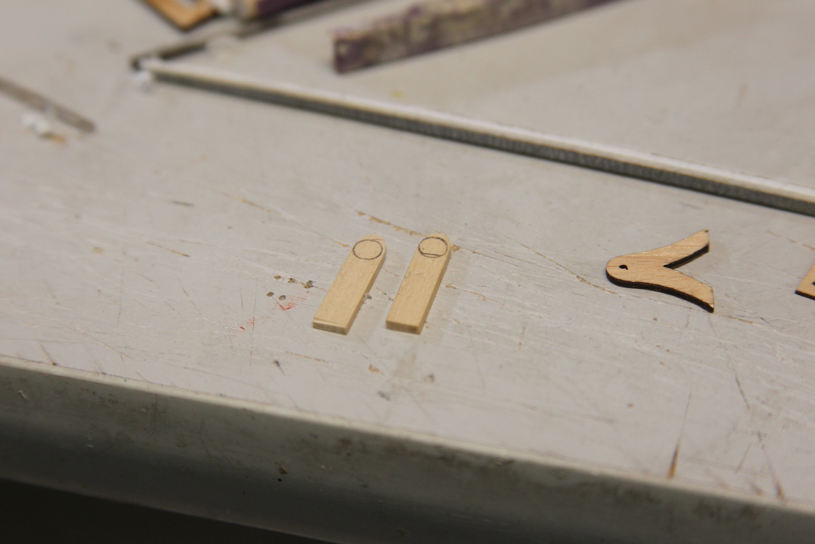
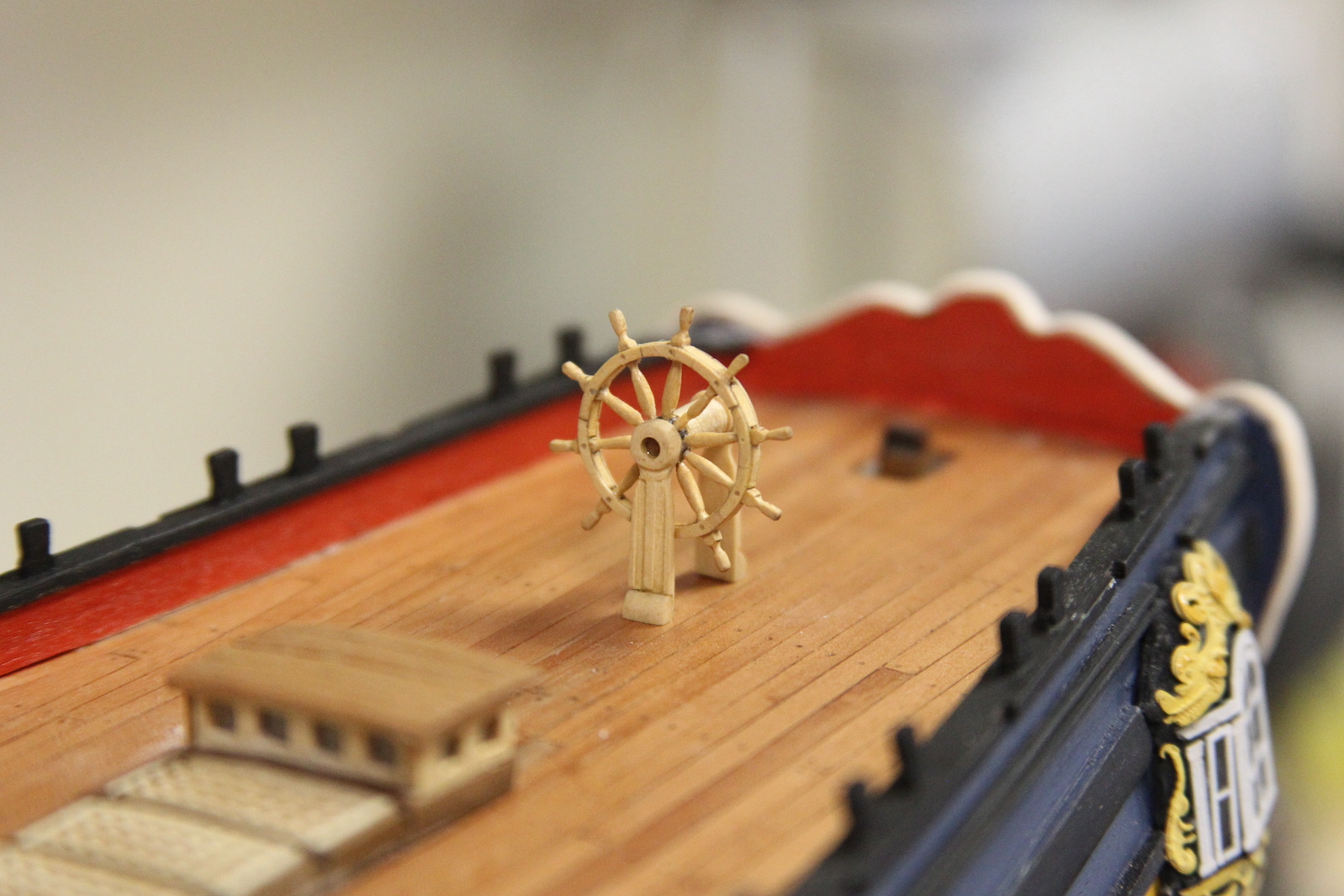
The barrel is turned on my Proxxon miniature lathe to form the base, a small ridge, and two ends that will fit into the wheel and the stanchions. The stanchions are carved boxwood – sanded and shaped, then given some texture down the center for a decorative flair. The funky looking “V” shaped piece in the picture below was the stanchion provided in the kit which does not conform to what I’ve seen in the Swan class documentation, however I used it to ensure proper scale. The assembled wheel is positioned (not glued) on the deck to check size and fit.
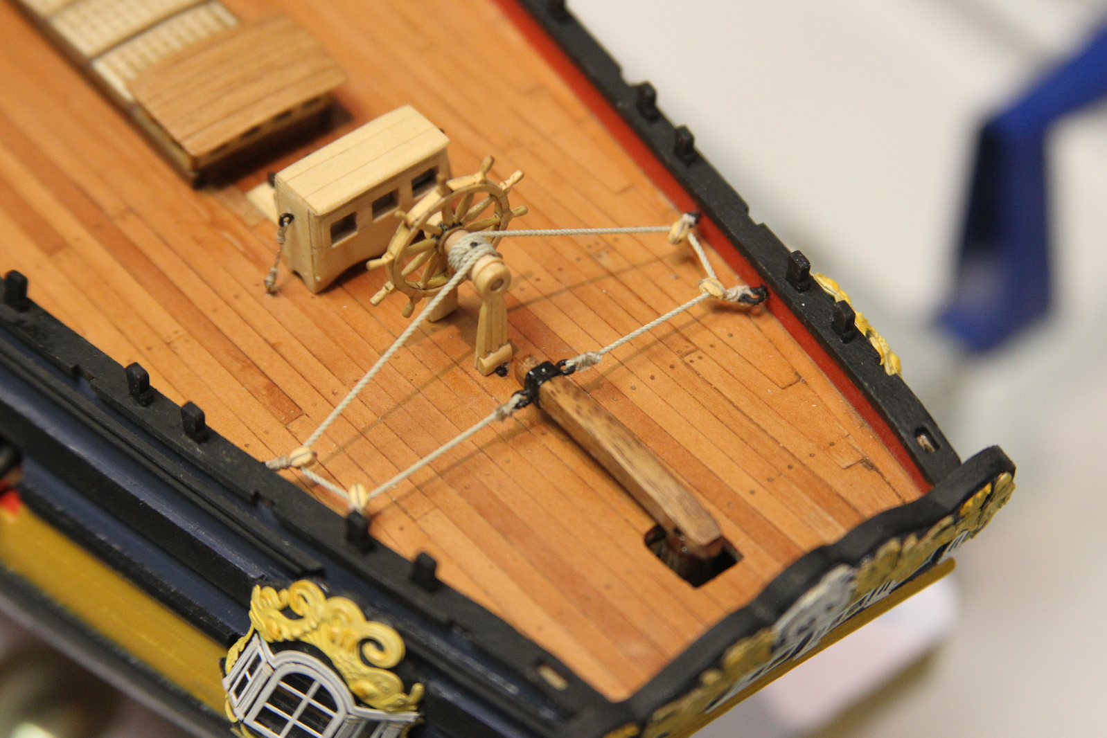
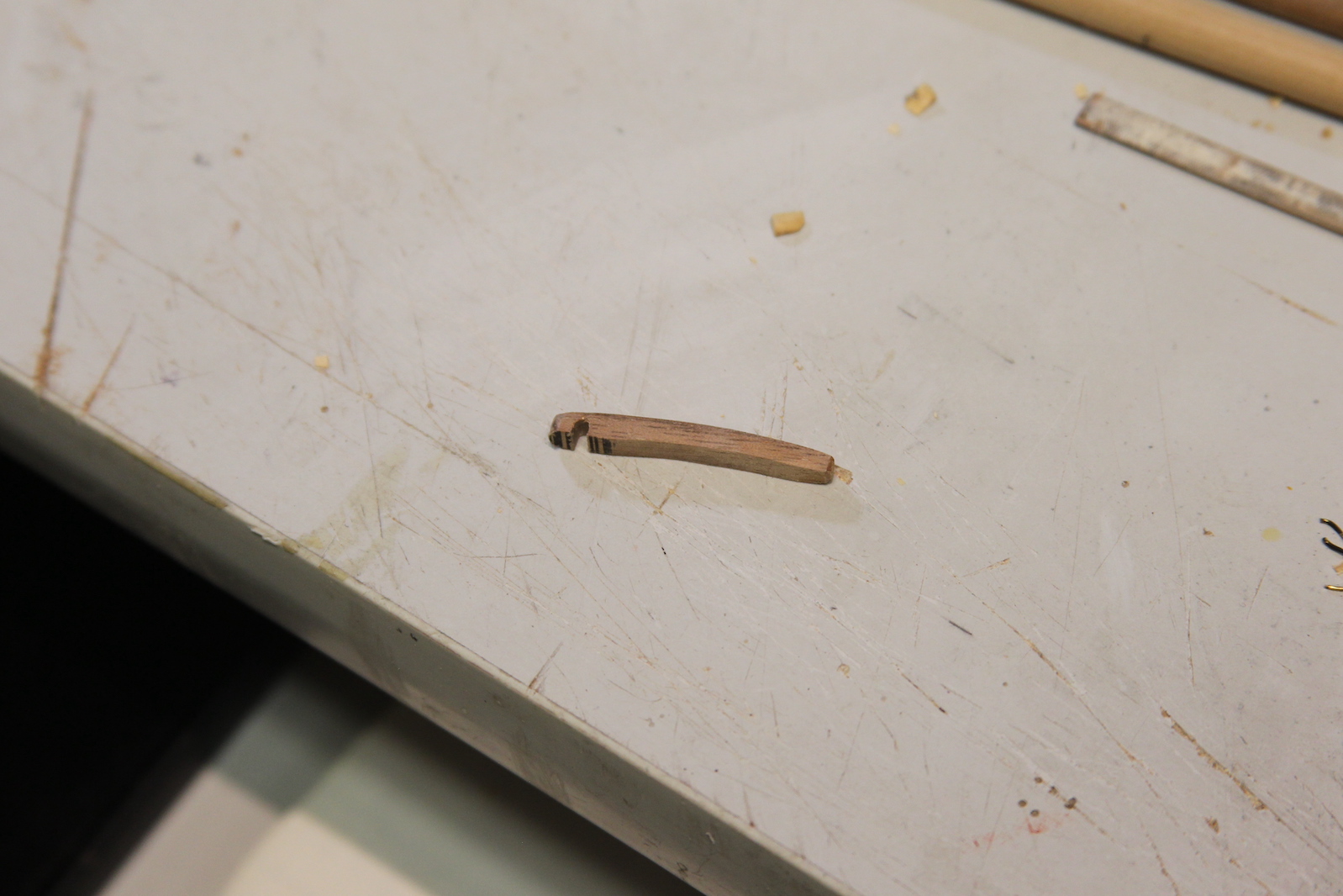
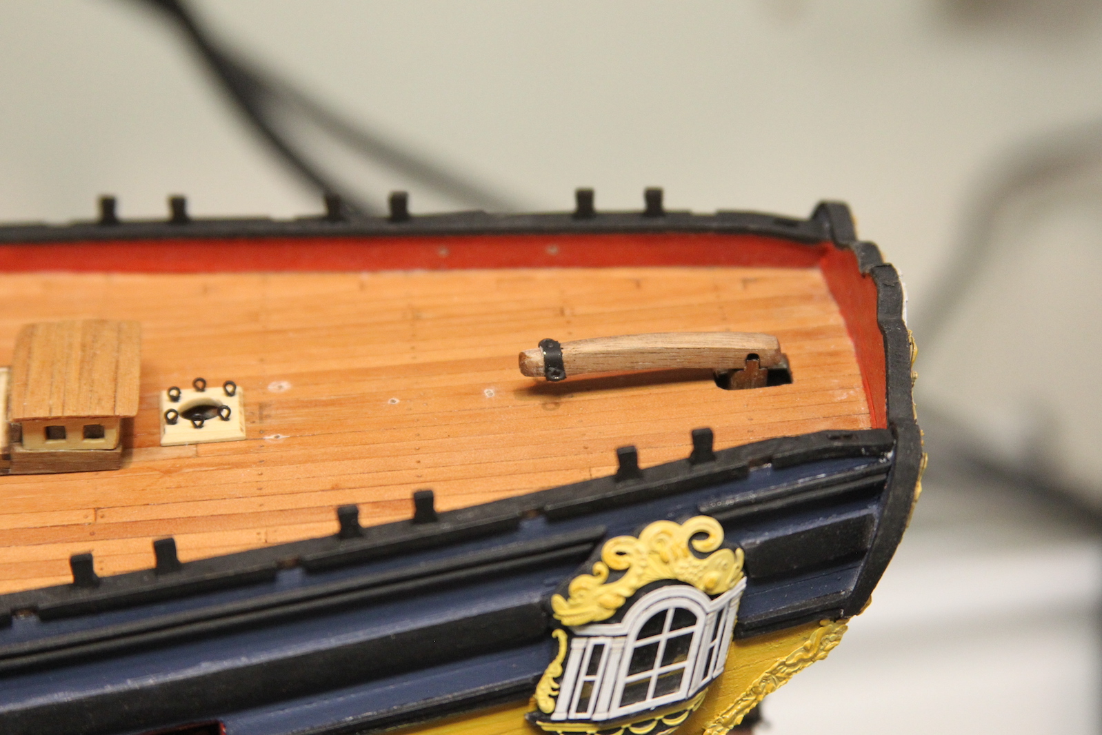
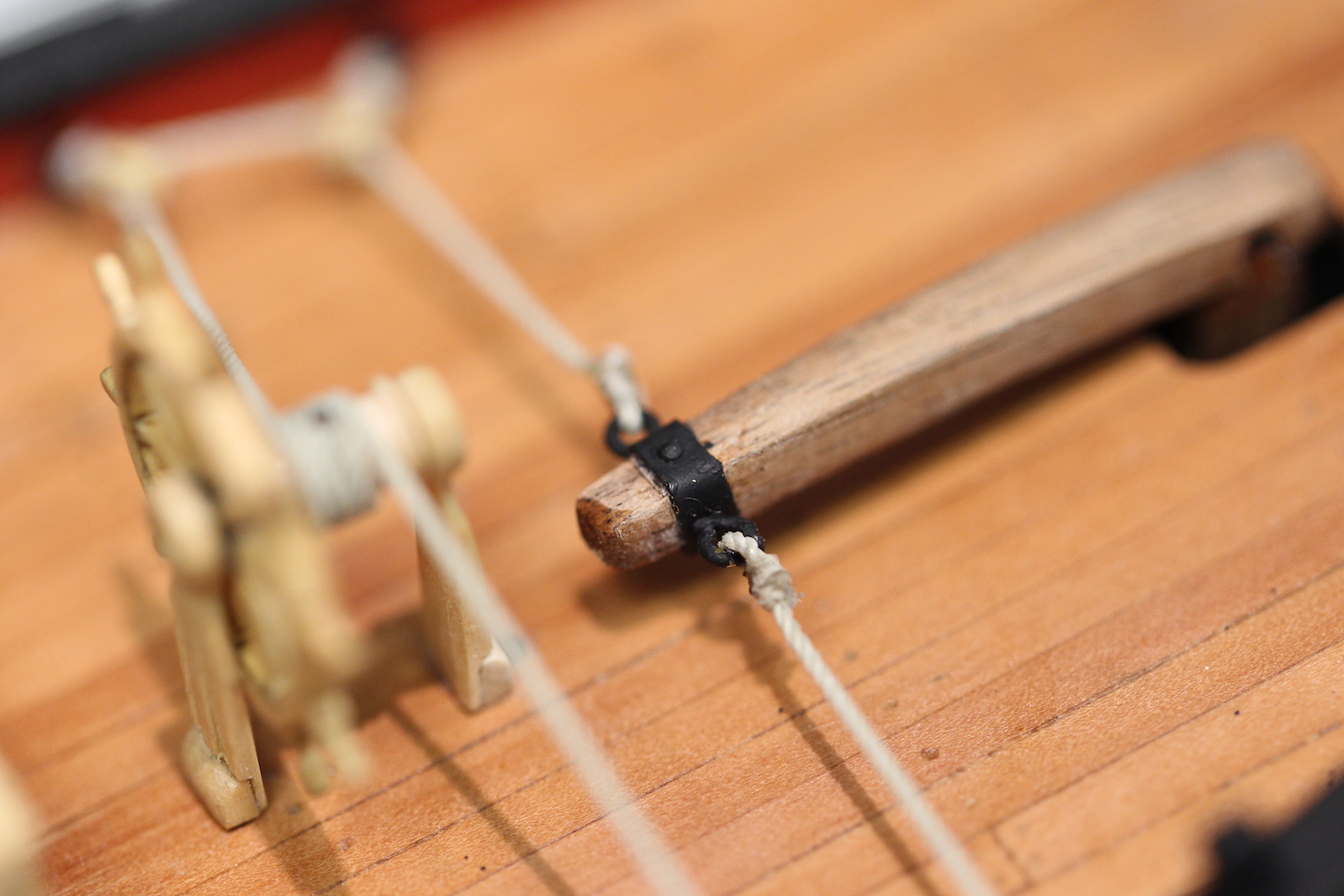
Next up, the tiller – which is attached to the top of the rudder and does the actual steering of the ship. It’s a pretty simple piece cut and shaped from 5mm x 5mm piece of walnut and notched at the base to fit the rudder. The tiller is rigged to the wheel (as shown in the illustration at the beginning of the post) with rope tied to eyelets on each side of a metal band at the head.
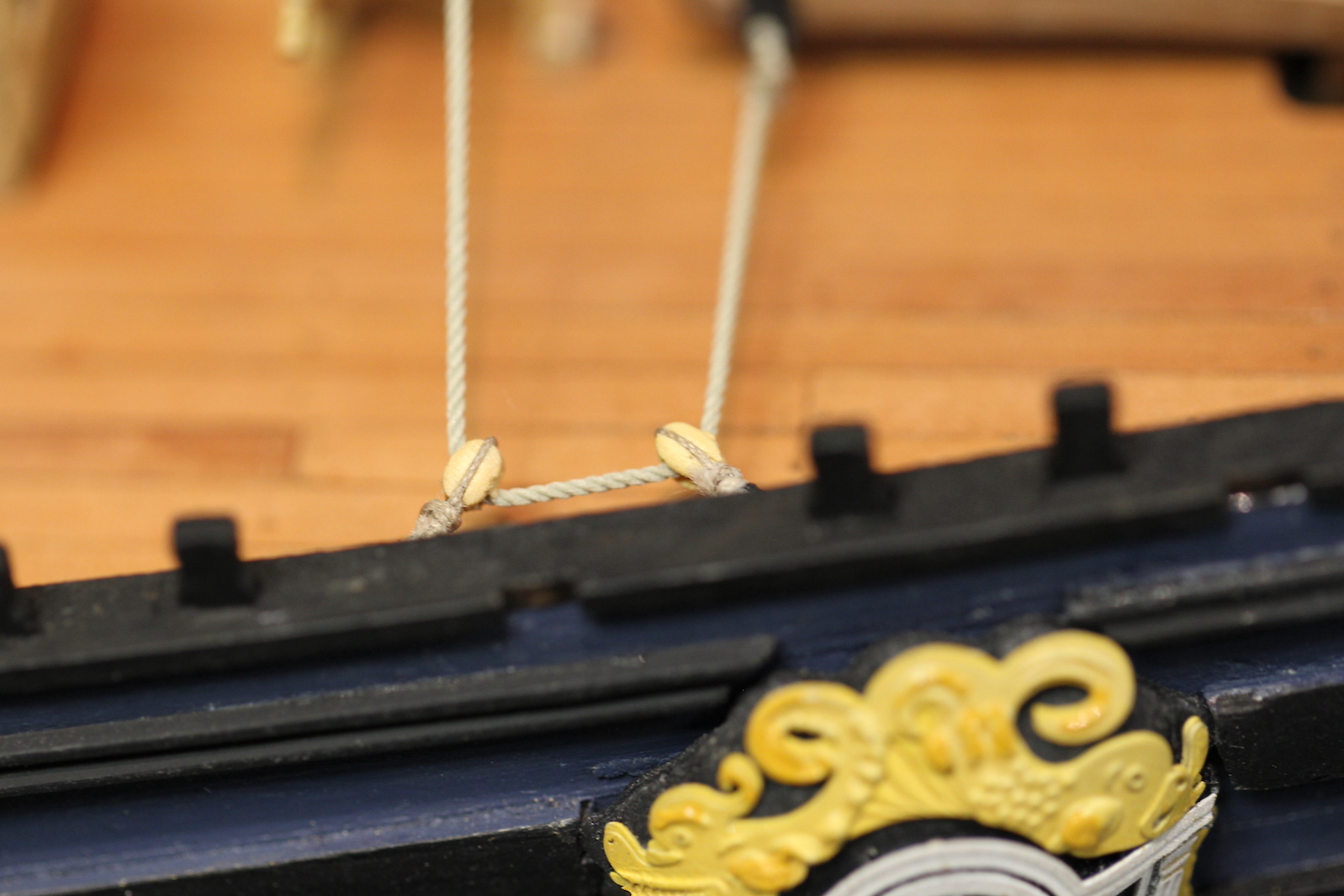
For the rigging I used .6 mm rope (since I imagined it needed to be pretty hefty stuff) attached to boxwood blocks which are subsequently fixed to the bulwarks with eye bolts. The rope is wrapped around the wheel barrel five times then through the corresponding set of blocks on the other bulwark. The wrap is attached to the barrel with a bolt that serves as a stopper which limits the amount the rudder can be turned. This TINY (.020″) bolt was very difficult to get into place without getting glue all over the rope and discoloring it.


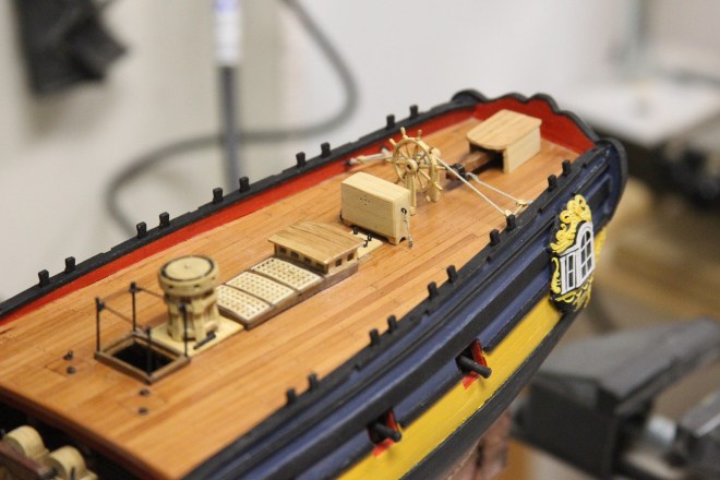
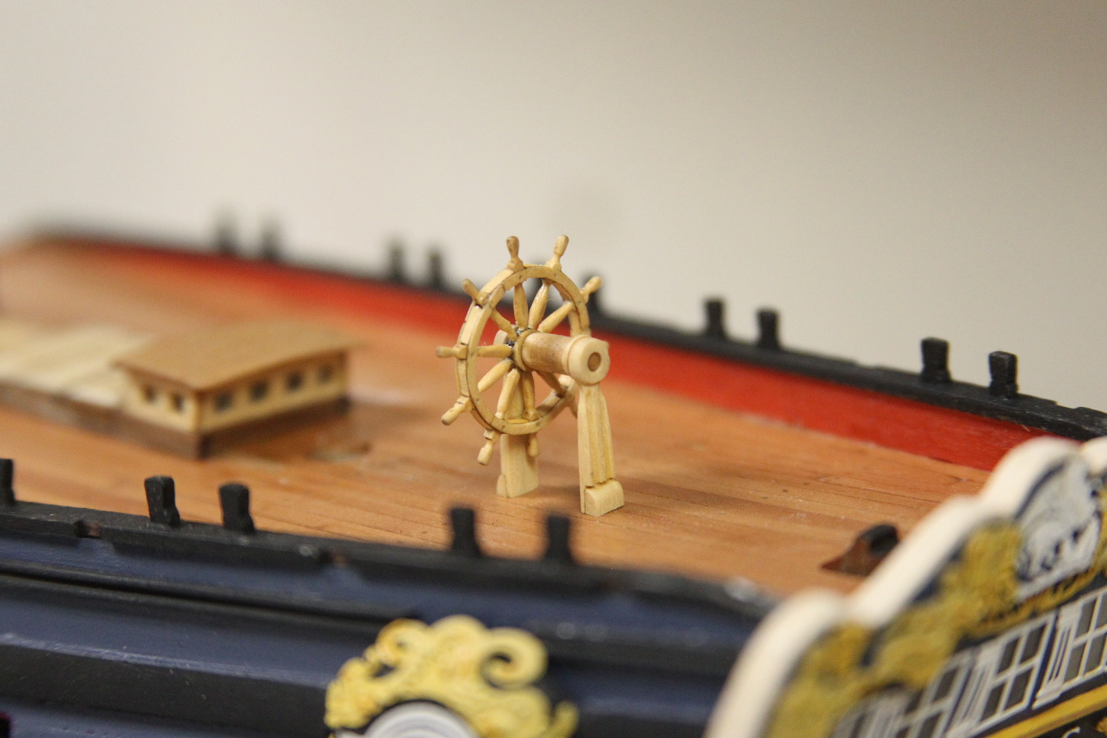
The wheel is permanently fixed into position. Notice I’ve also fixed into position the binnacle that was finished earlier. It was necessary to fix this into position to ensure the wheel was in the proper place. The back end of the binnacle can be (and is) pretty close to the mizzen mast. However, there must be sufficient space between the binnacle and the wheel for the helmsman to stand and maneuver. This little spacing detail is something that is often overlooked (or poorly accounted for) in many plans and builds. Finally, the rudder head housing it put together with boxwood and veneer strips to match the look/feel of the carriage house just on the other side of the mizzen. I also wanted to ensure I had enough room between the rudder housing and the stern to put an ensign staff clamp (more to come on that later).