Planking the Hull – Layer 2

   The second layer of planking takes a bit more precision than the first layer as it is the one that’s visible – obviously.  With the Peg – and other ships of the era – the hull was coppered, so that’s kind of an excuse to perhaps not pay as much attention to detail since any errors will be covered.  However, I hadn’t decided yet if I wanted to copper the hull, or leave it as wood; since I personally feel that can be more pleasing to the eye.  Either way, I went about my second layer of planking with as much precision as I could.

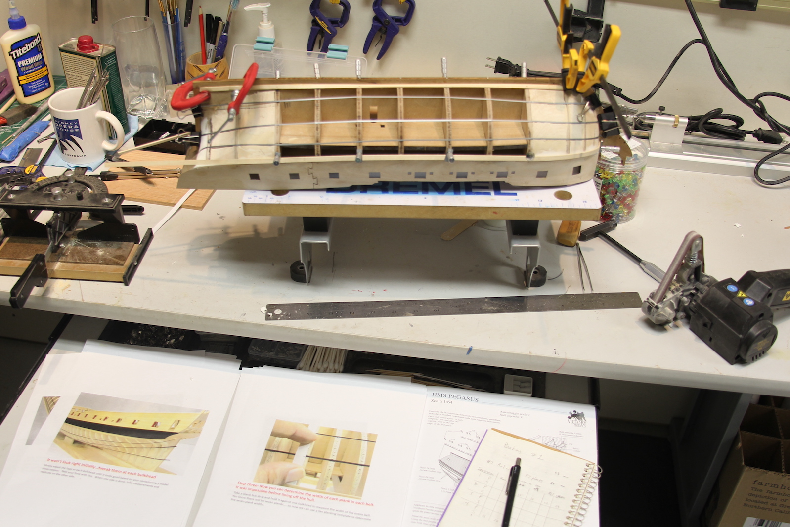
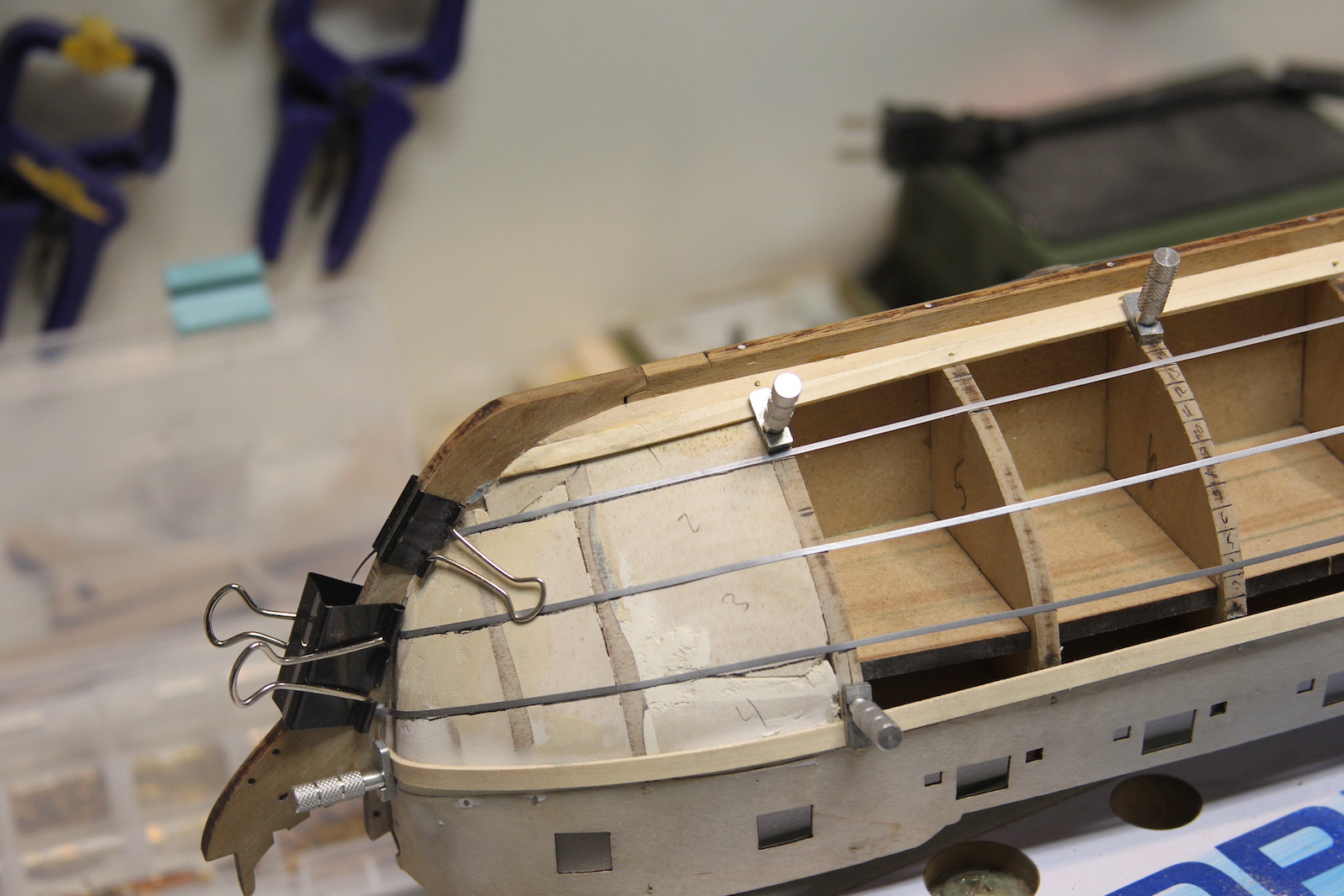
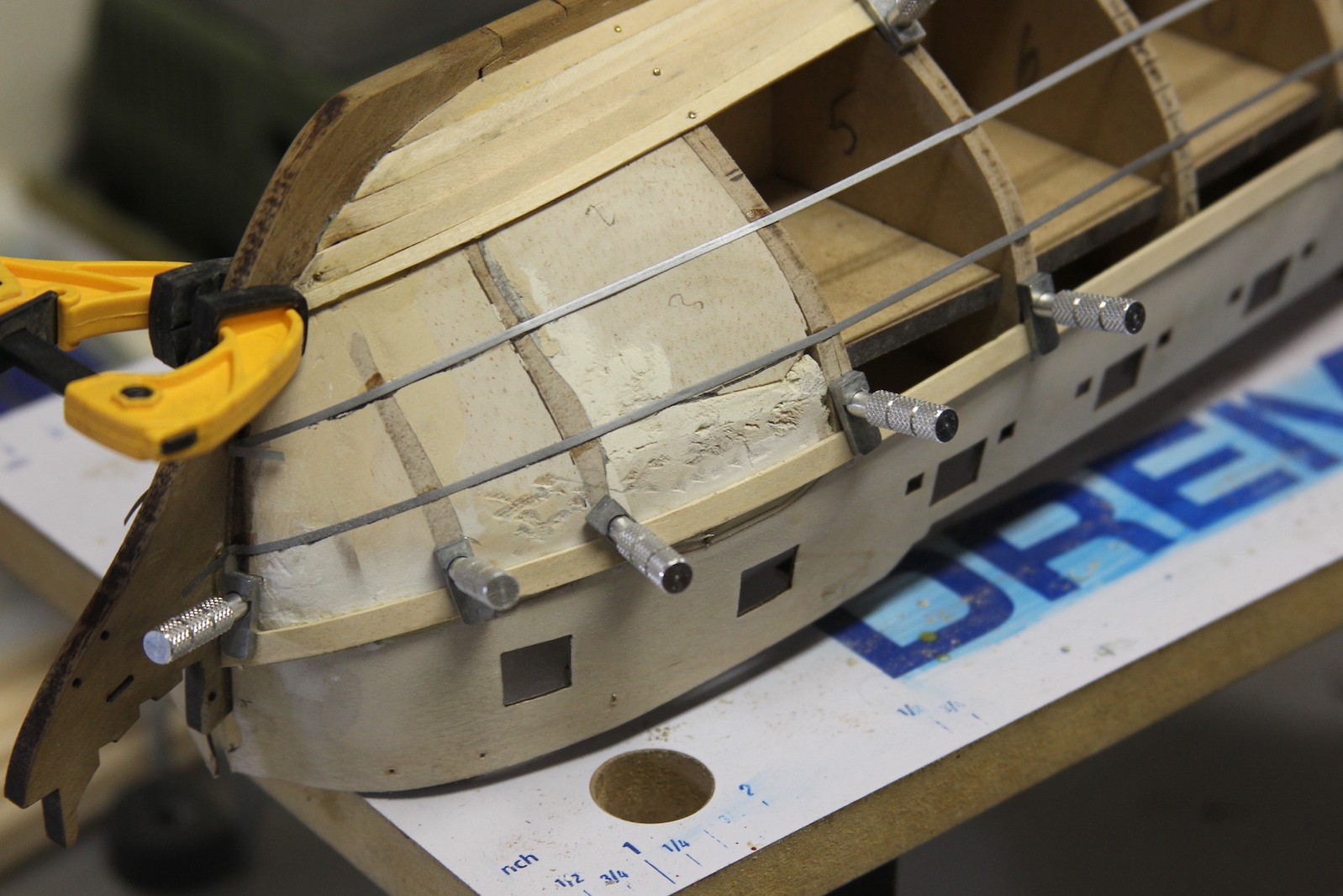
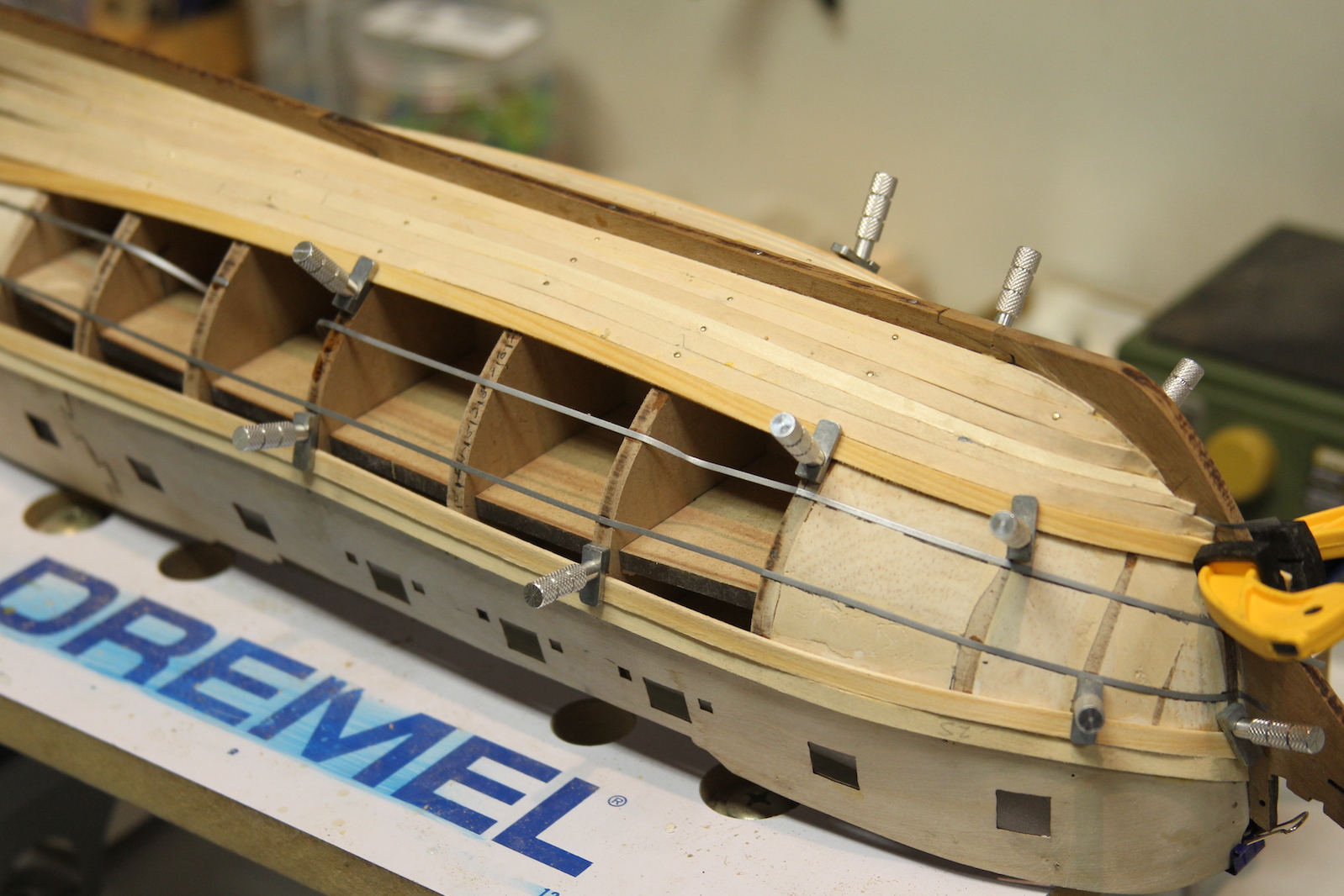
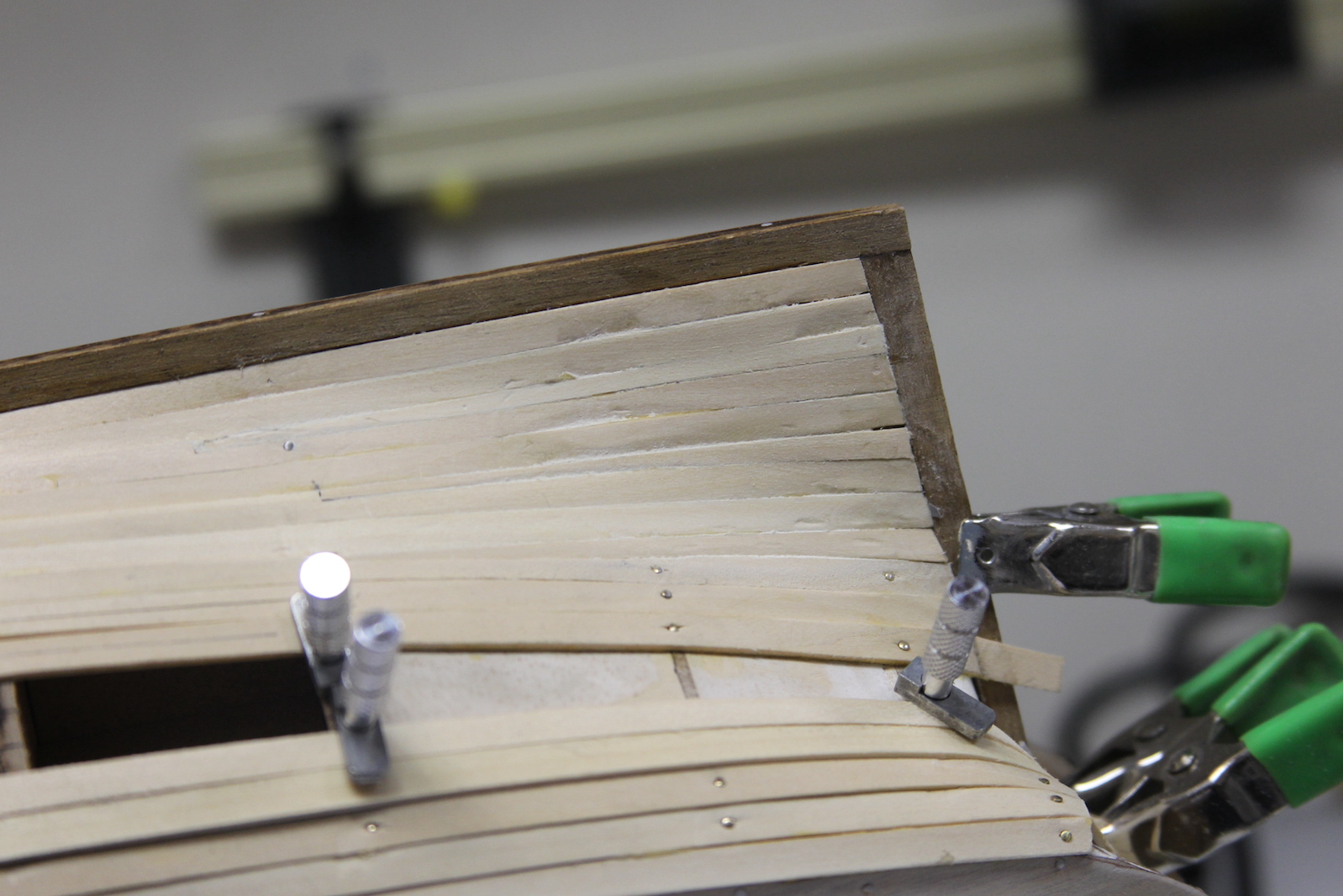
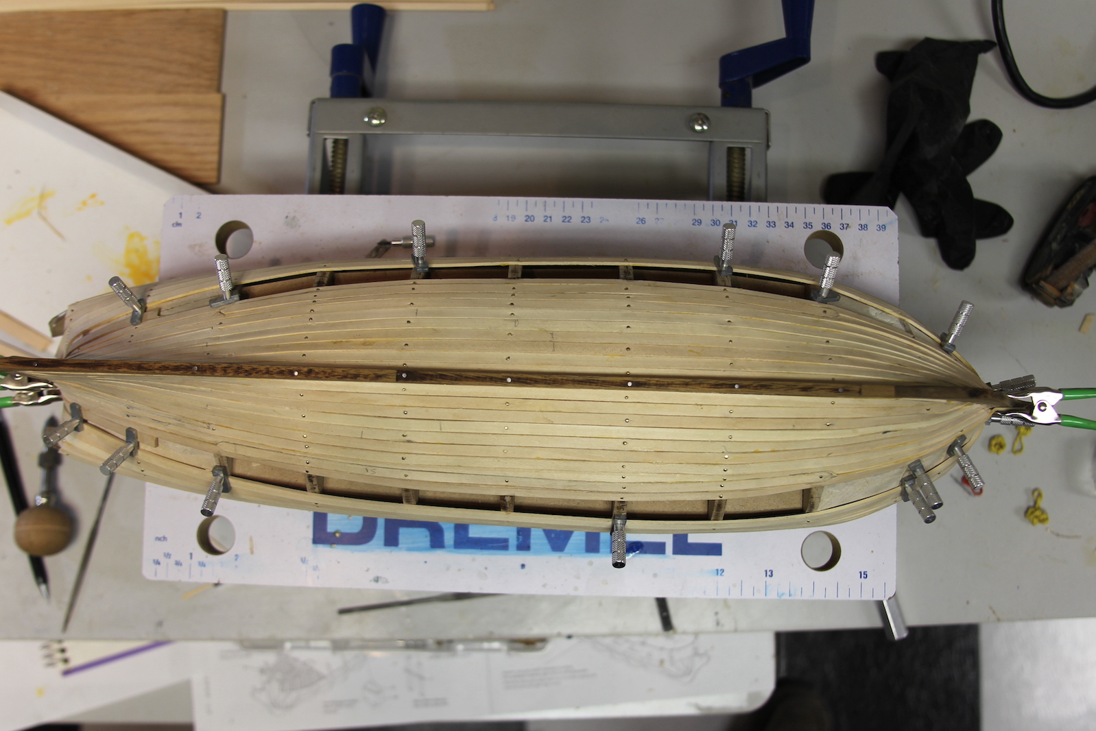
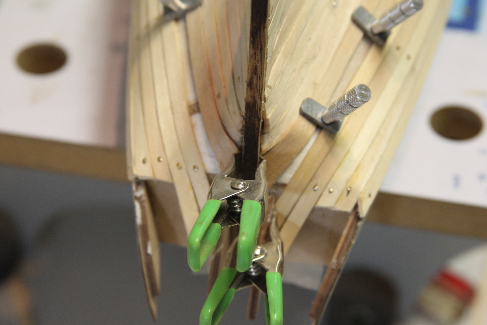
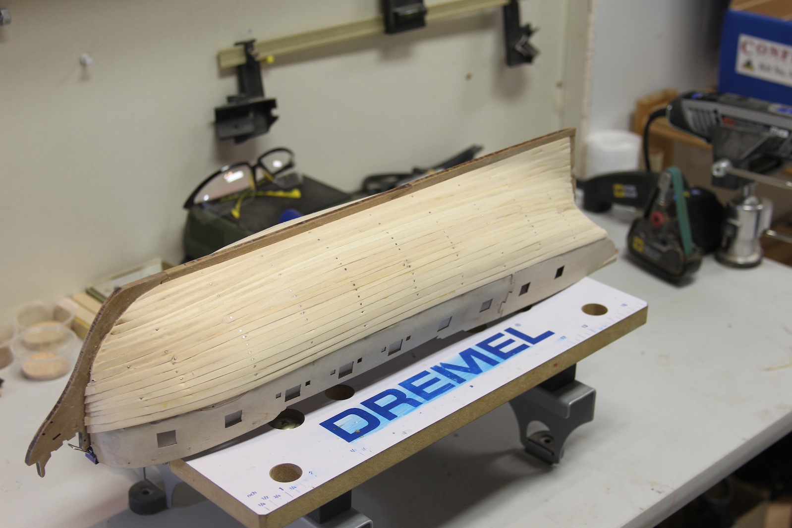
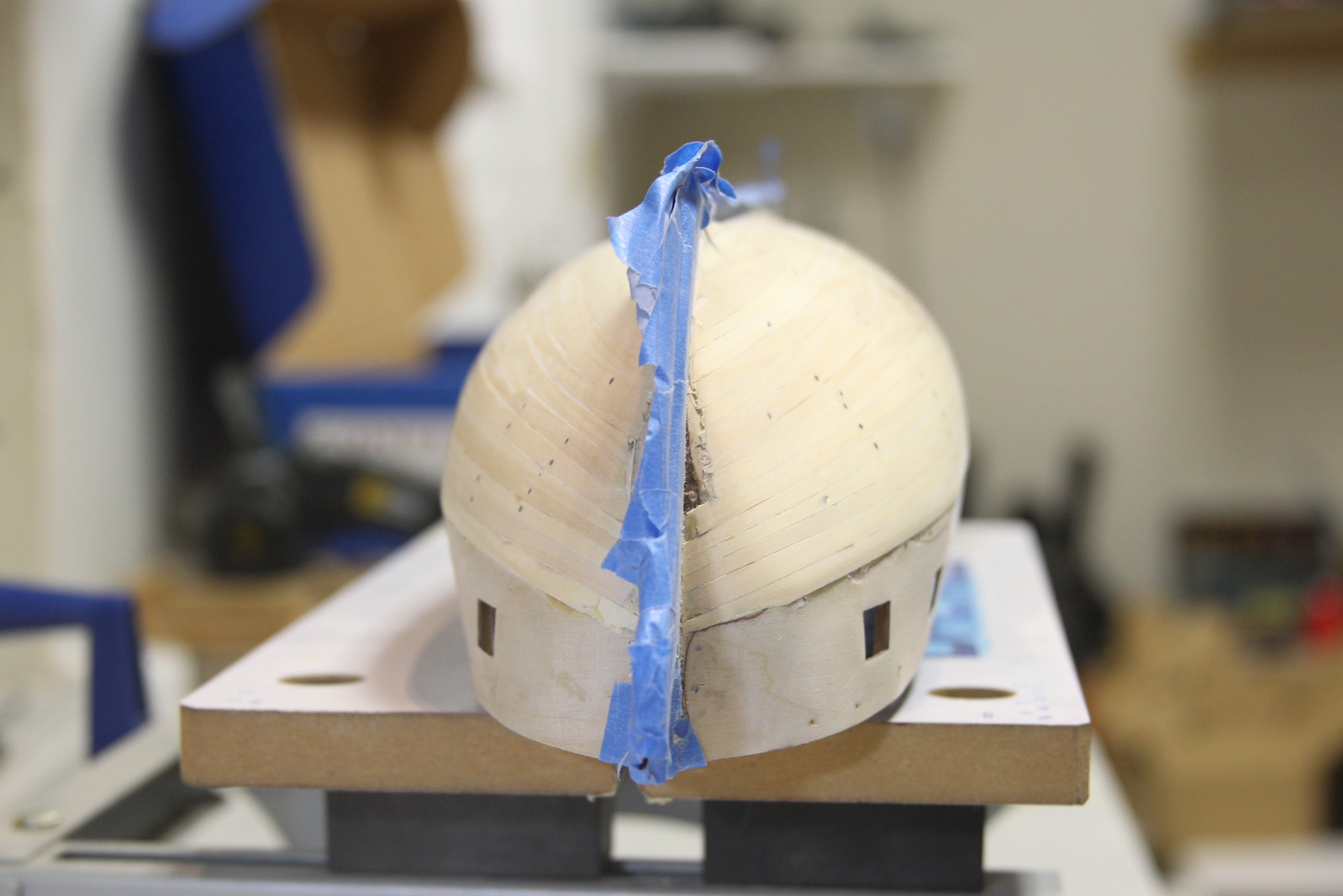
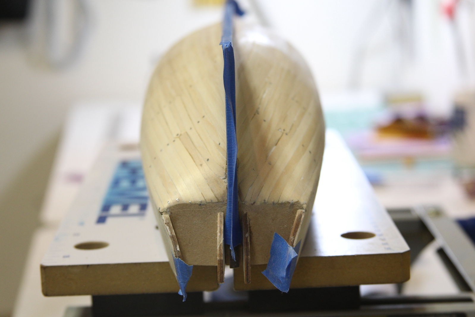
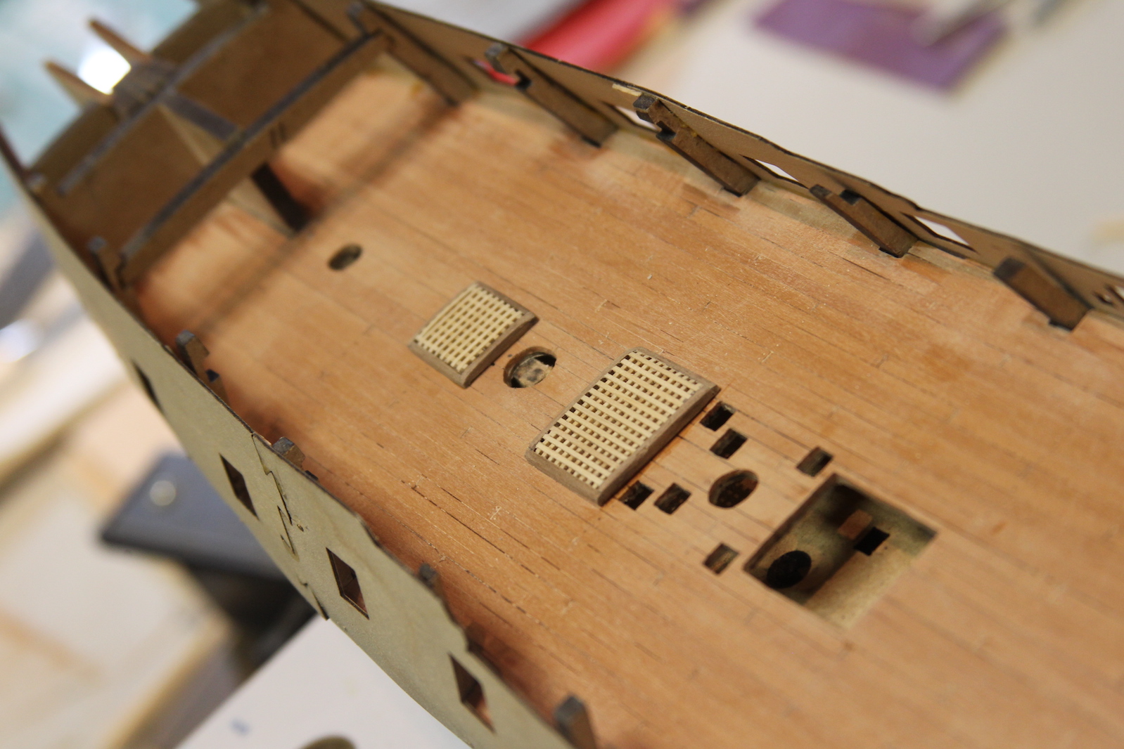
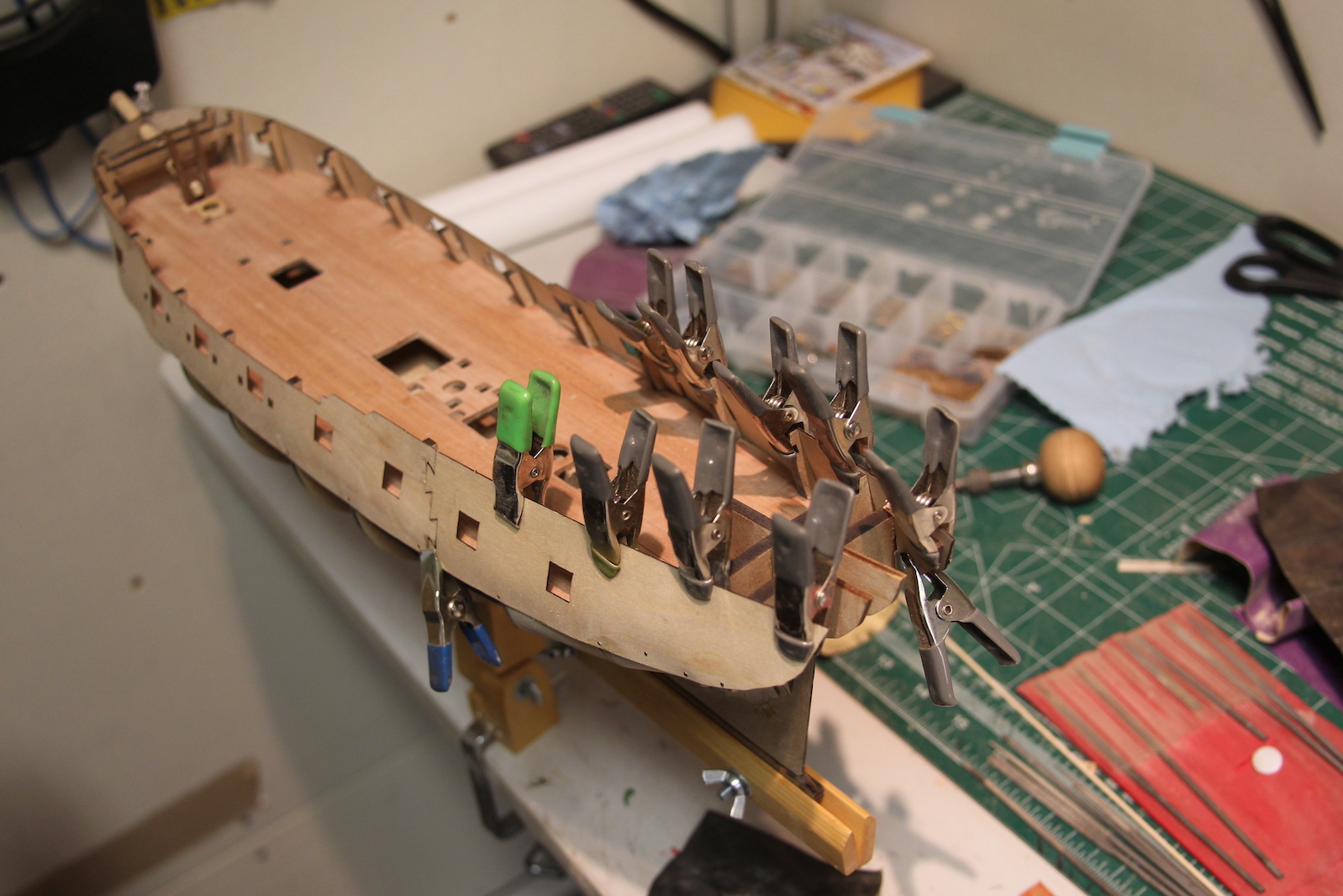
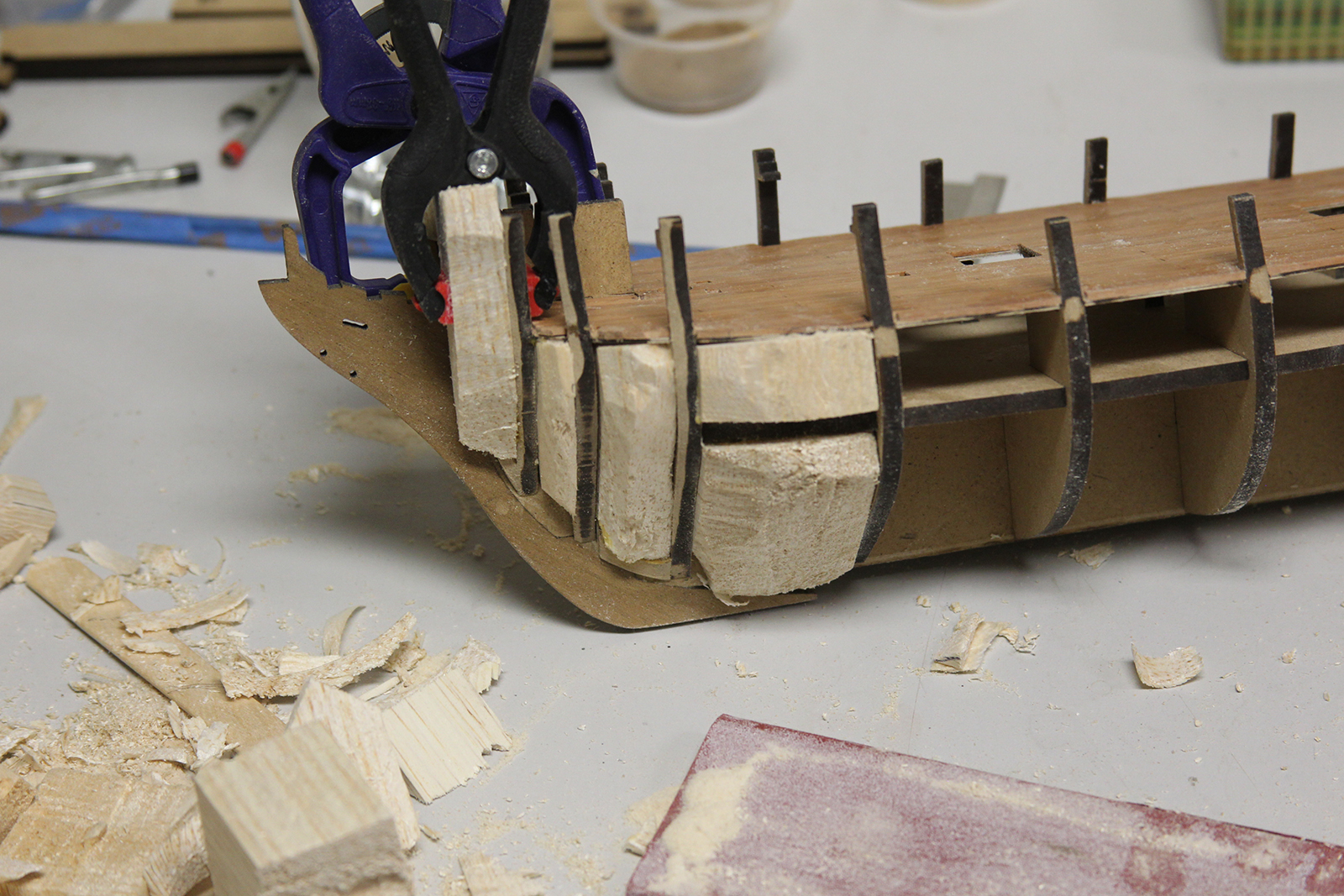
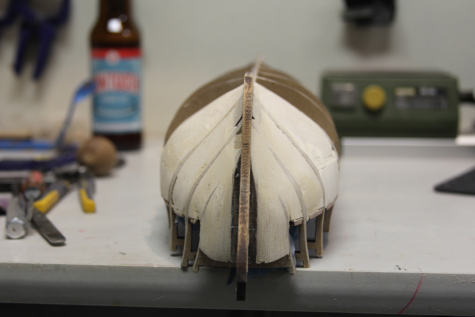
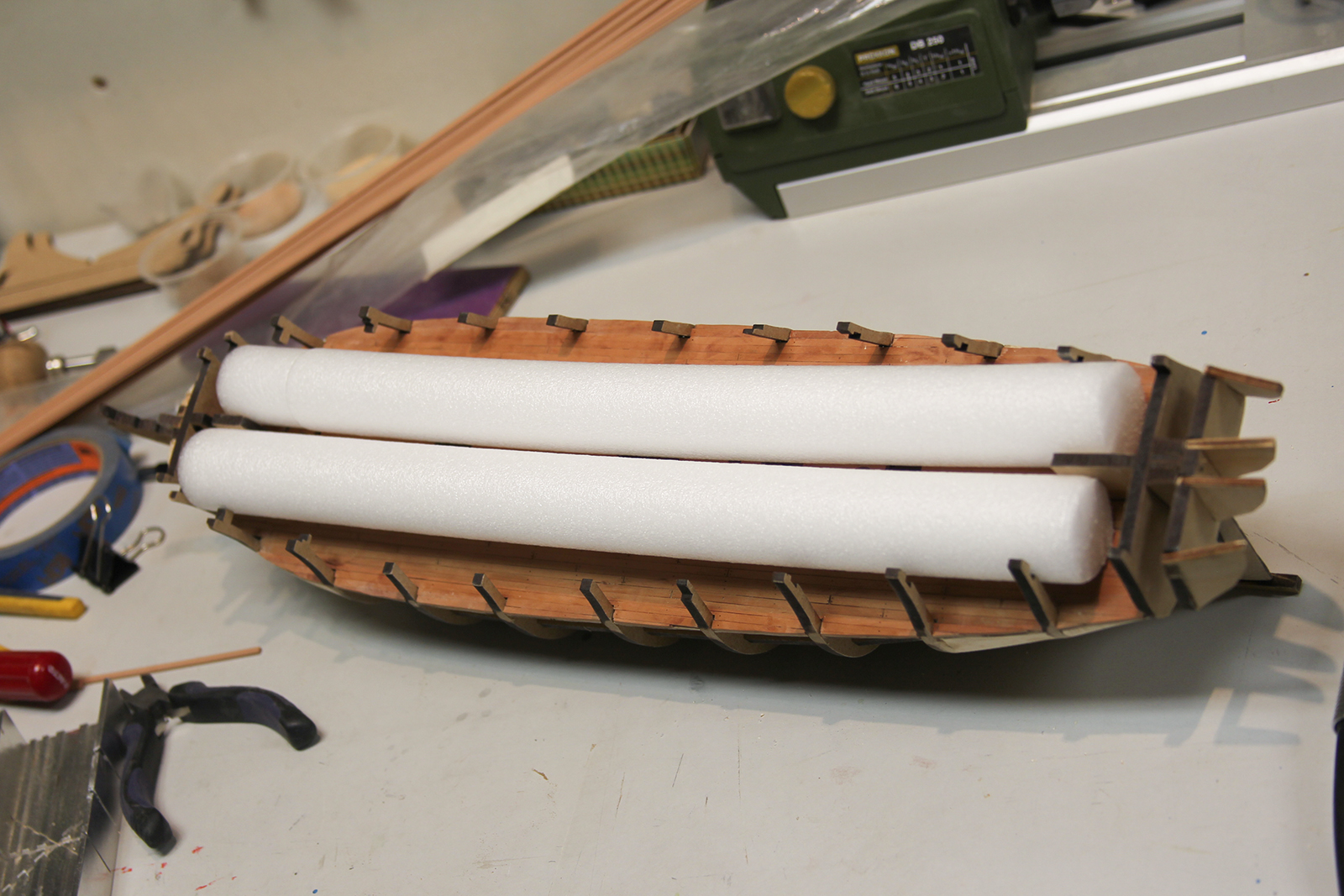
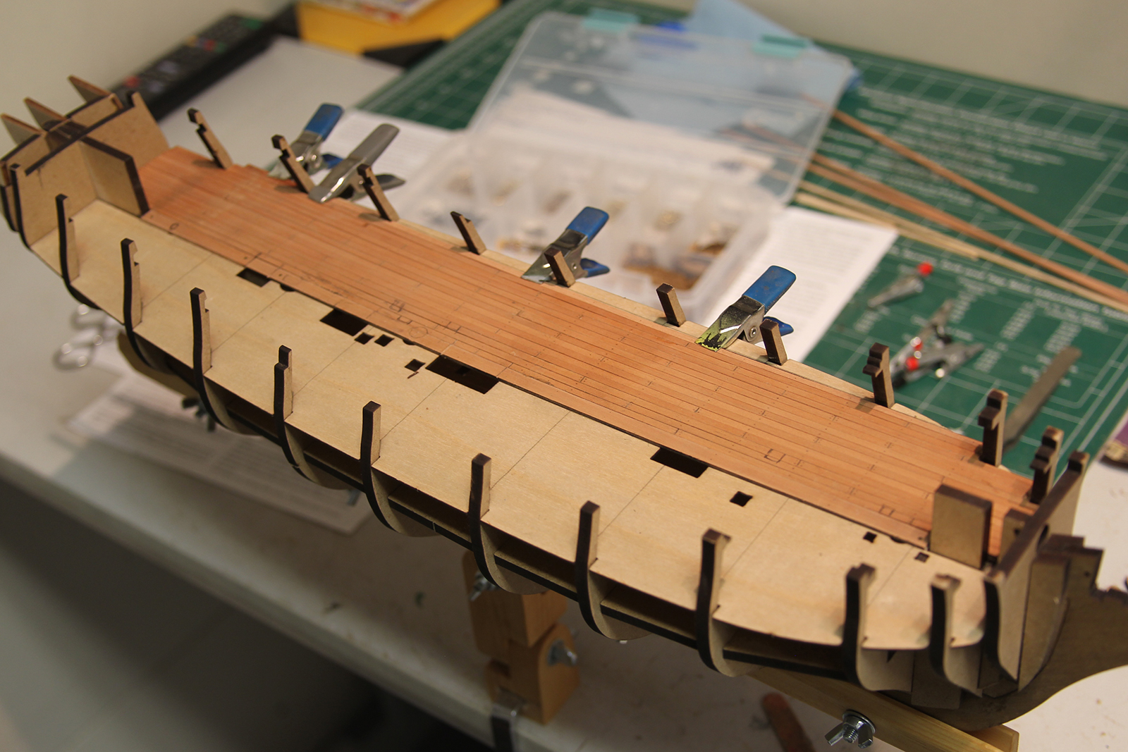
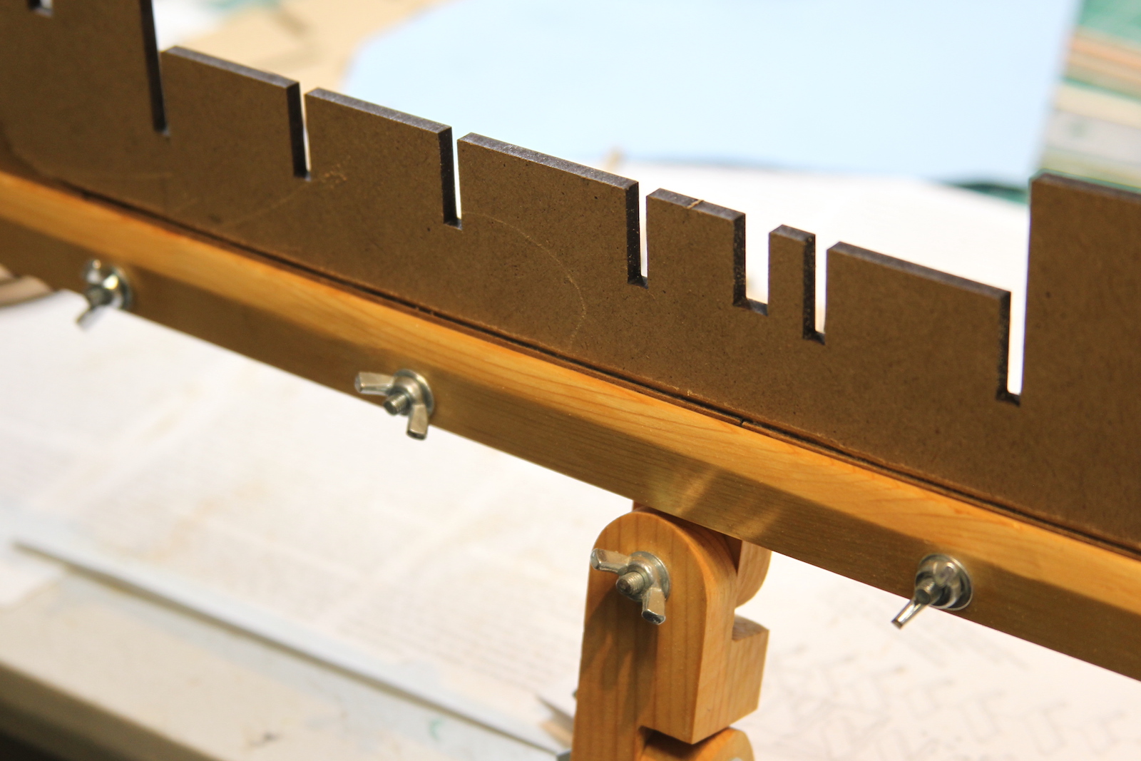
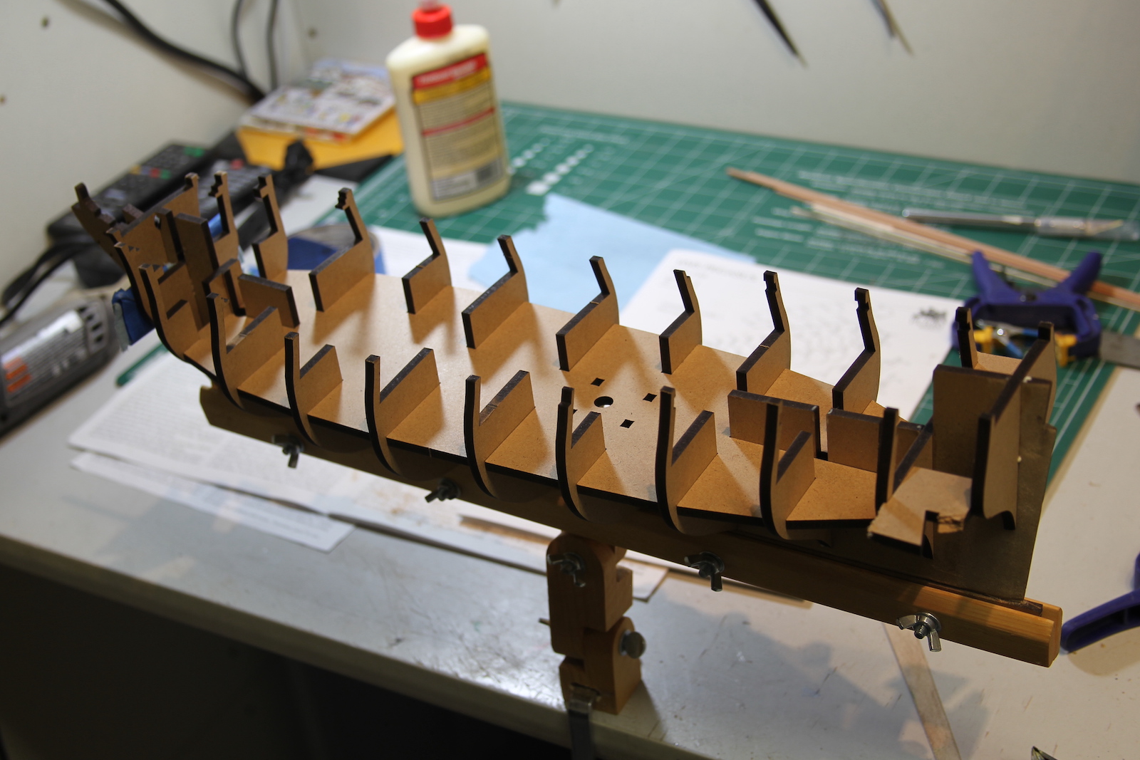
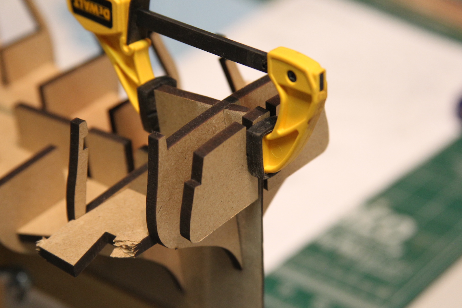
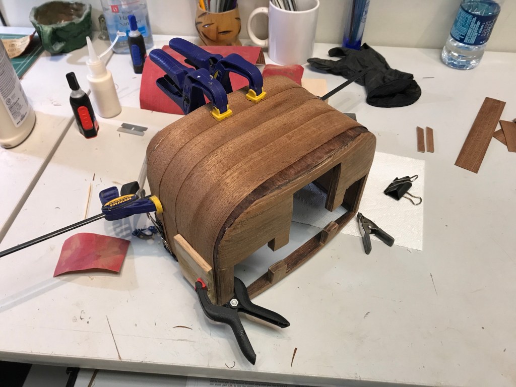
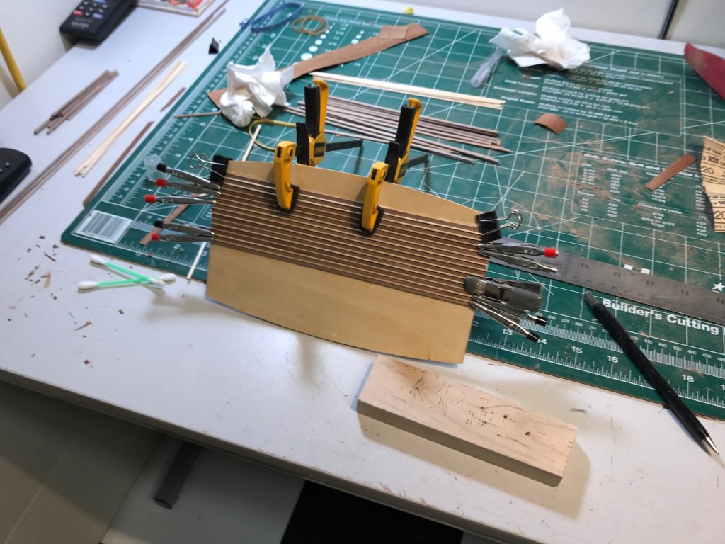
    I needed to do a fair amount of trimming prior to the second layer, so that’s where I start. Curbing the stern and crating a new rabbet for the walnut planks. After that, I split the hull into three sections instead of the four I used for the initial layer.  These ‘divider’ planks are just tacked there to help me count out the planks.  I then started planking from the bottom up and top down to meet in the middle. The kit provides walnut planks for the second layer, but there’s some pretty significant inconsistency in terms of color – so I did my best to separate the planks to get some coloring that was at least in the same ballpark.  As you’ll see later – I was only partially successful.  We’ll see how the bulwarks end up and then I’ll decide whether or not to do any staining – even though most of the planking is painted in some fashion.  

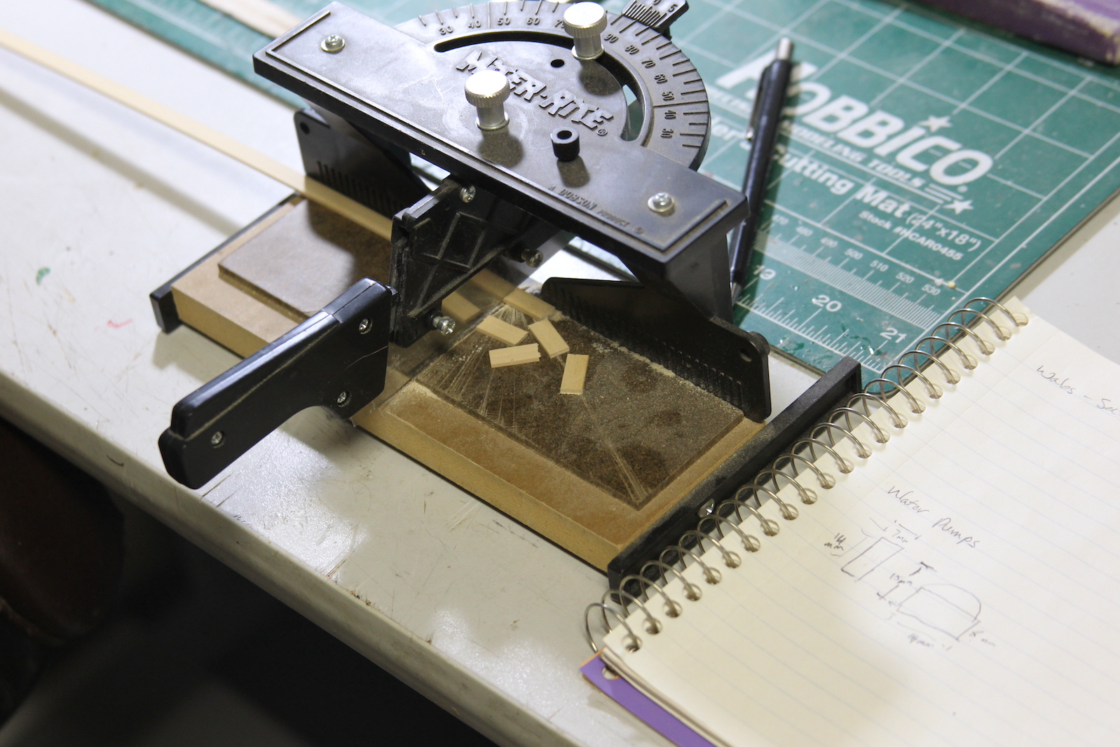
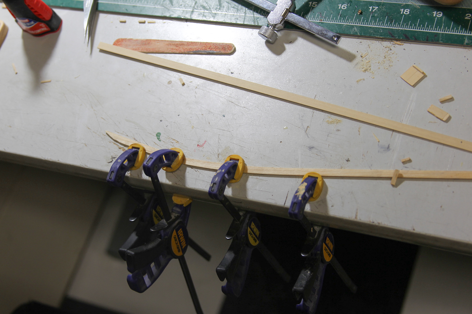
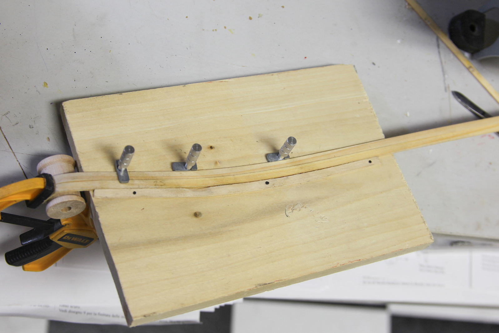
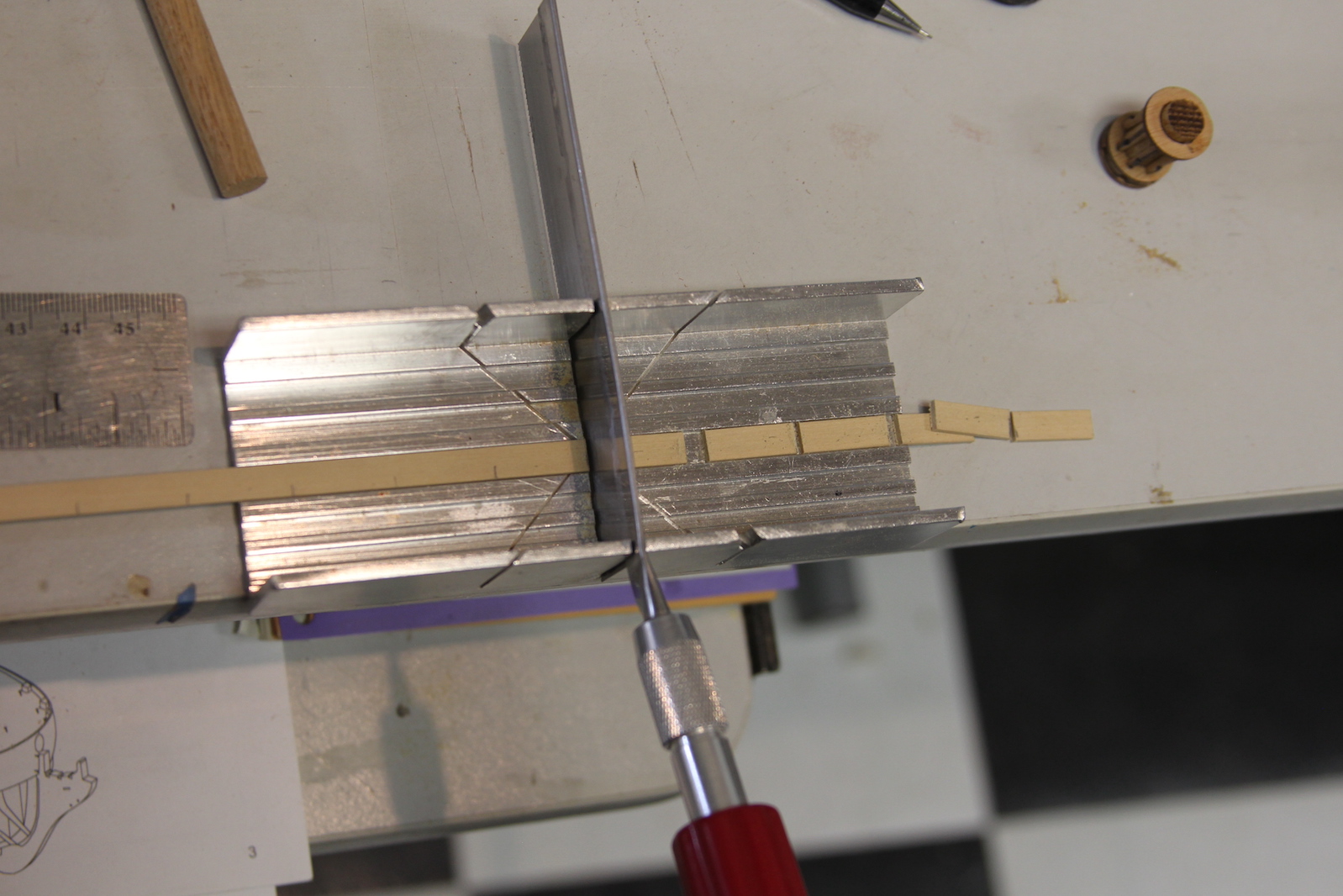
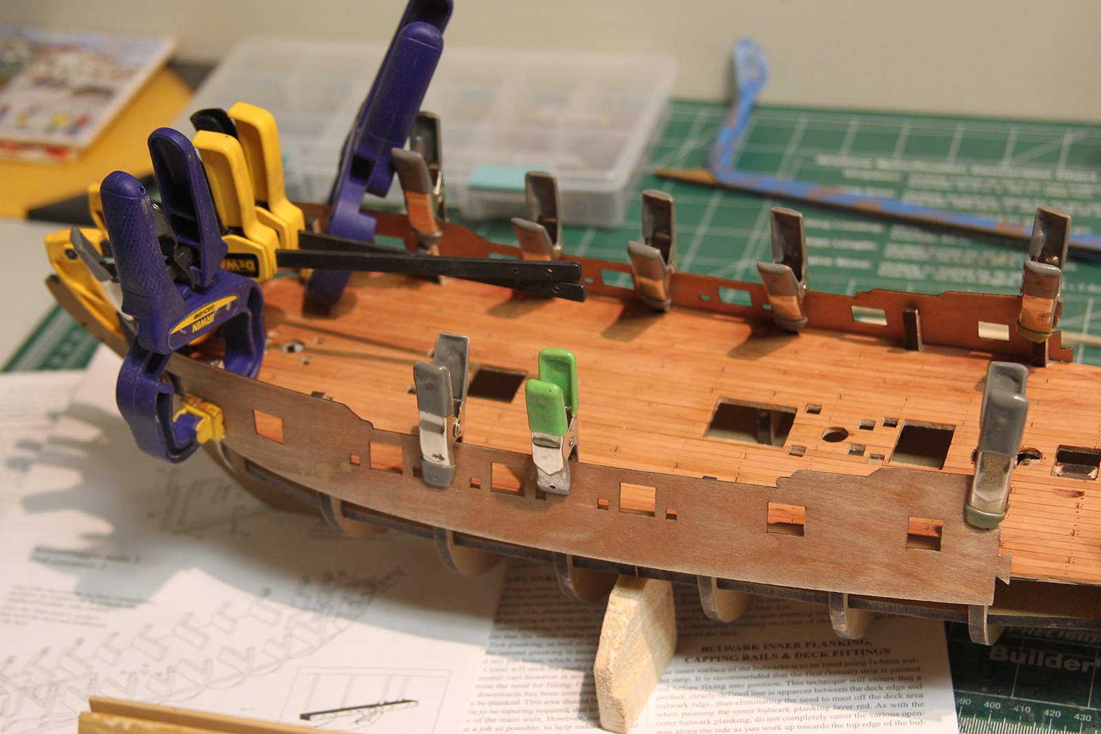
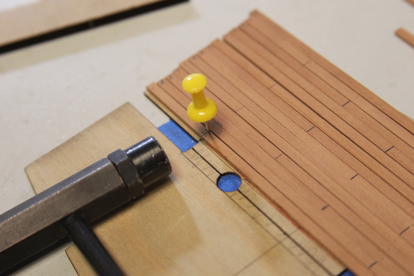
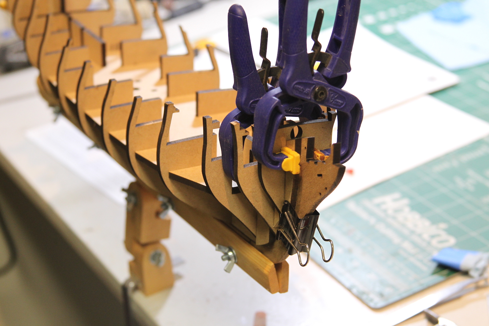
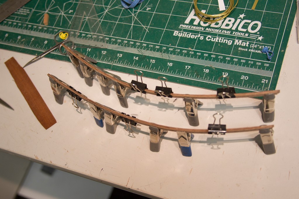
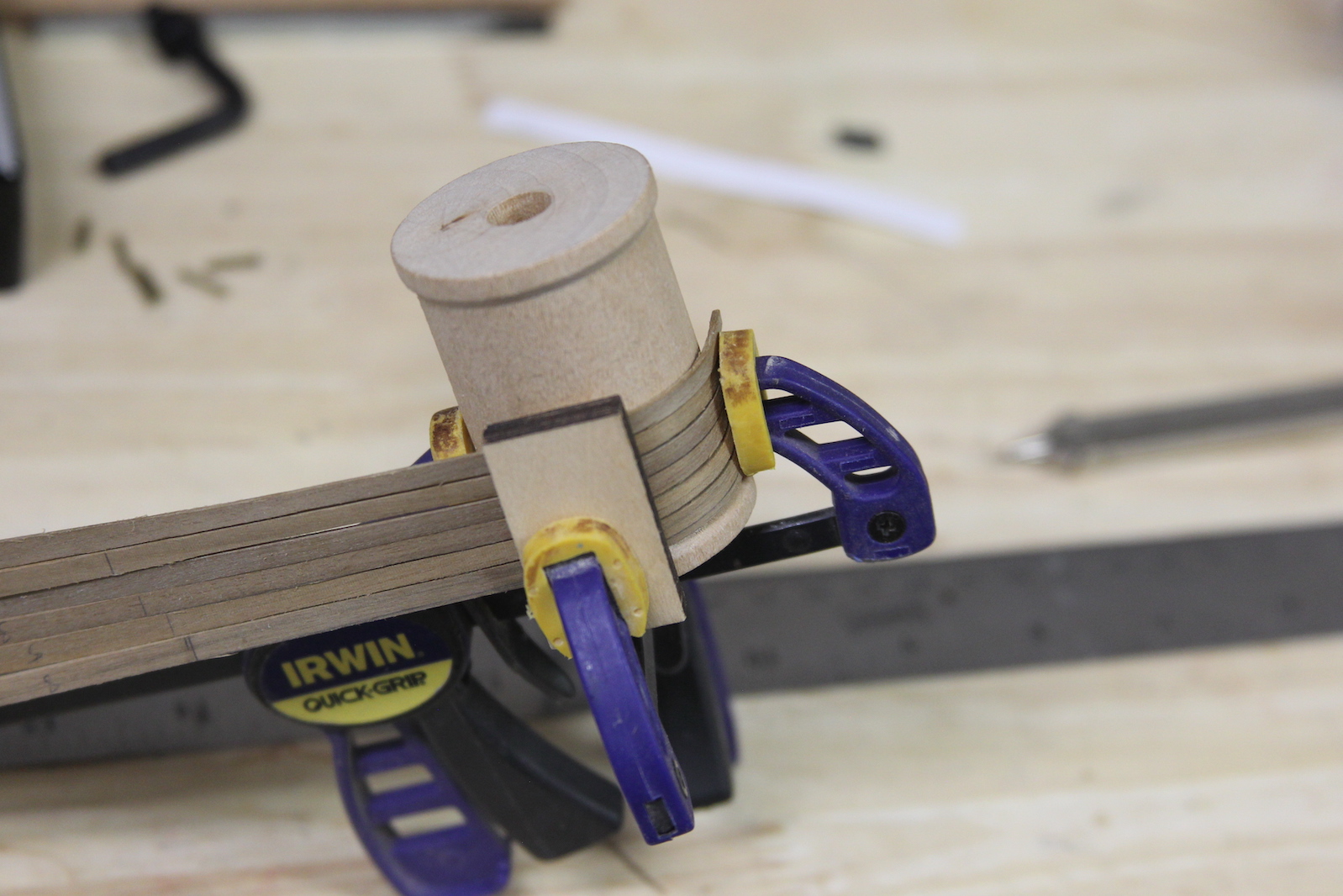
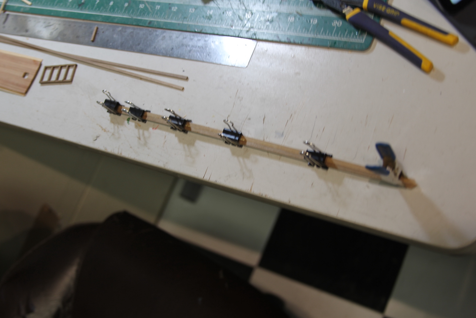
  I took the lessons I learned from the first planking and did a whole bunch of measuring and math to try and figure out how much to taper the planks for each section of the hull. If you take a look at some of the pictures you’ll see lots of little notes and marks along the way. Here’s the thing – while I definitely think this all benefitted me – it still ended up basically being ‘best guess’ with me measuring out the last section one bit at a time. After soaking and bending wood – it never seems to return to the same size, or I’m off by a fraction of a millimeter or something. Honestly, I think I’d have had more success with a harder wood like box or pear – but I didn’t really want to fork over the extra cash. I’ve already invested quite a bit into the deck wood as well as ropes, canons and other miscellaneous stuff. Besides – I was pretty sure I was going to end up coppering the hull. At any rate, the second layer is the same general process as the first – soak, bend, mount, glue.

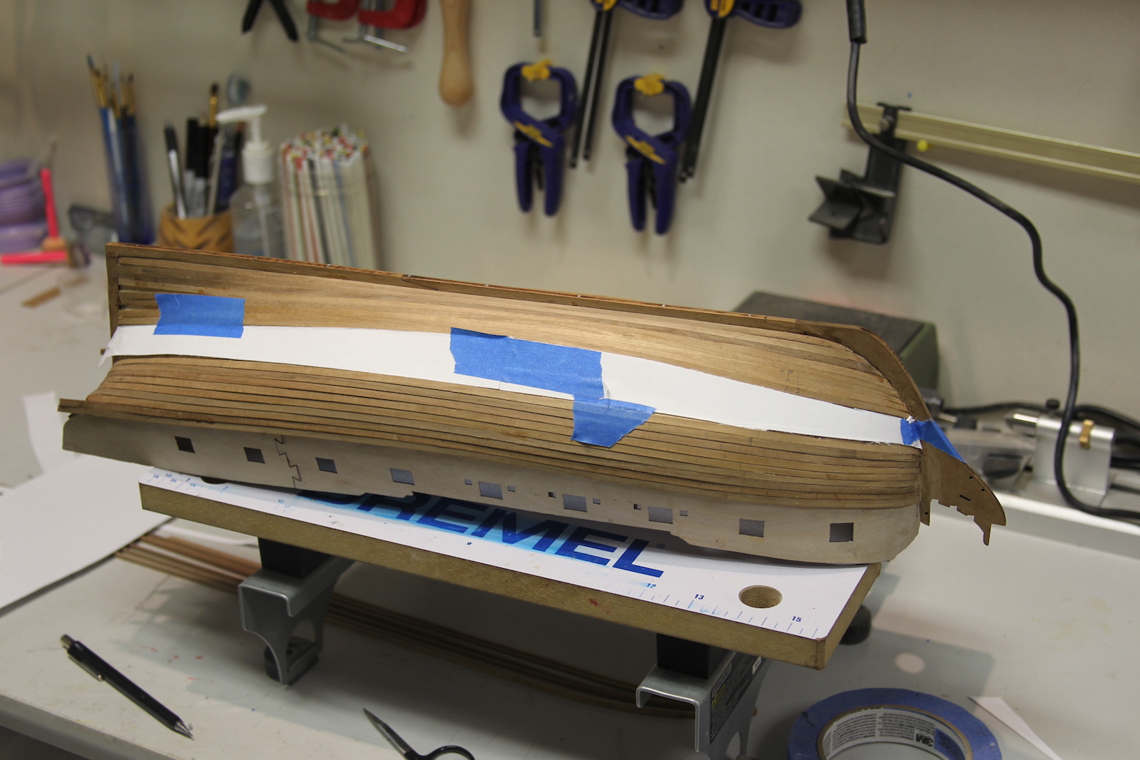
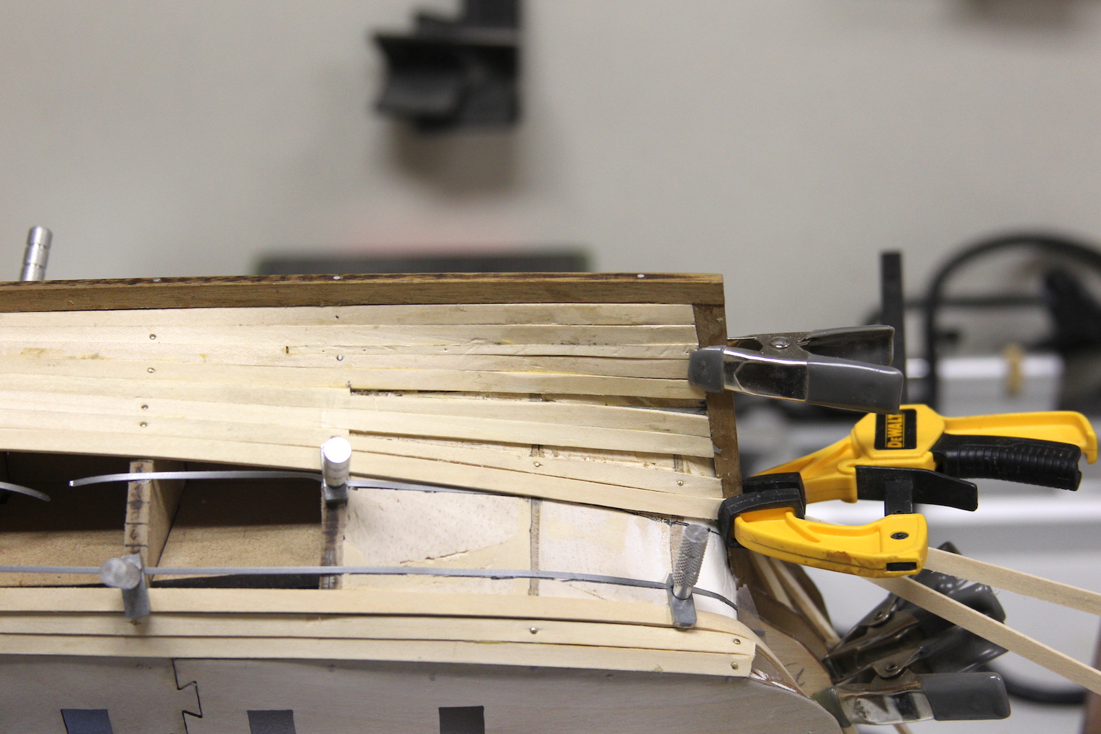
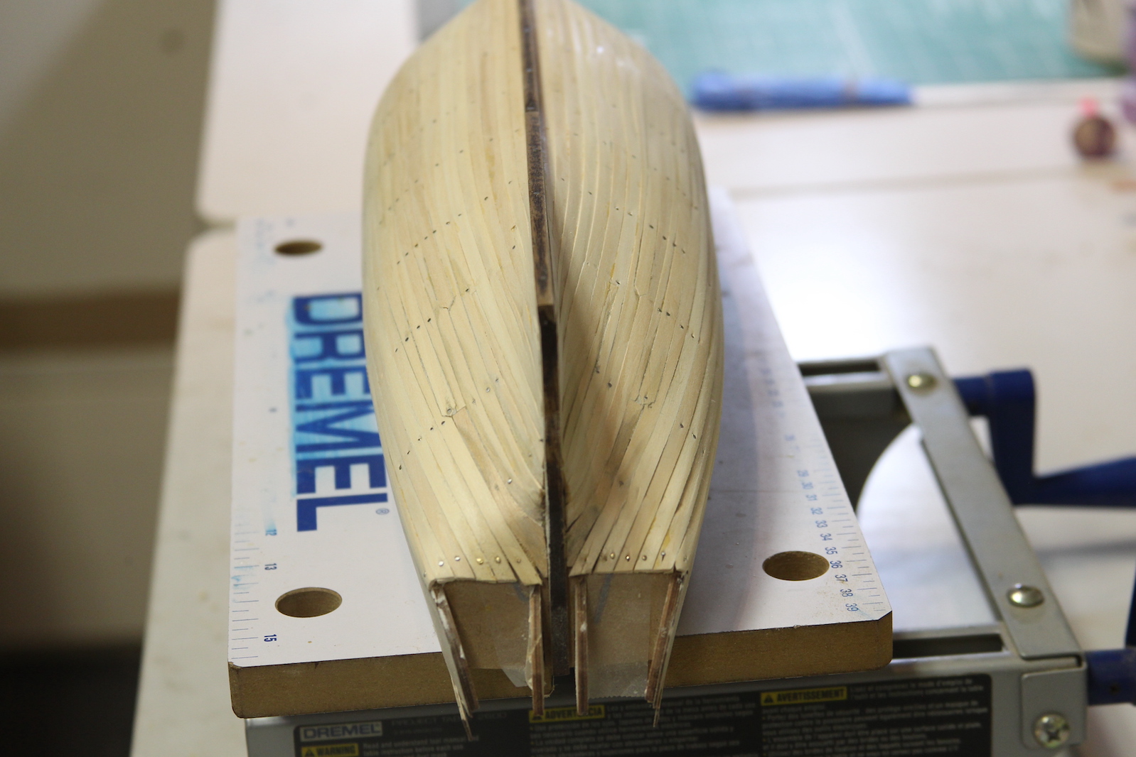
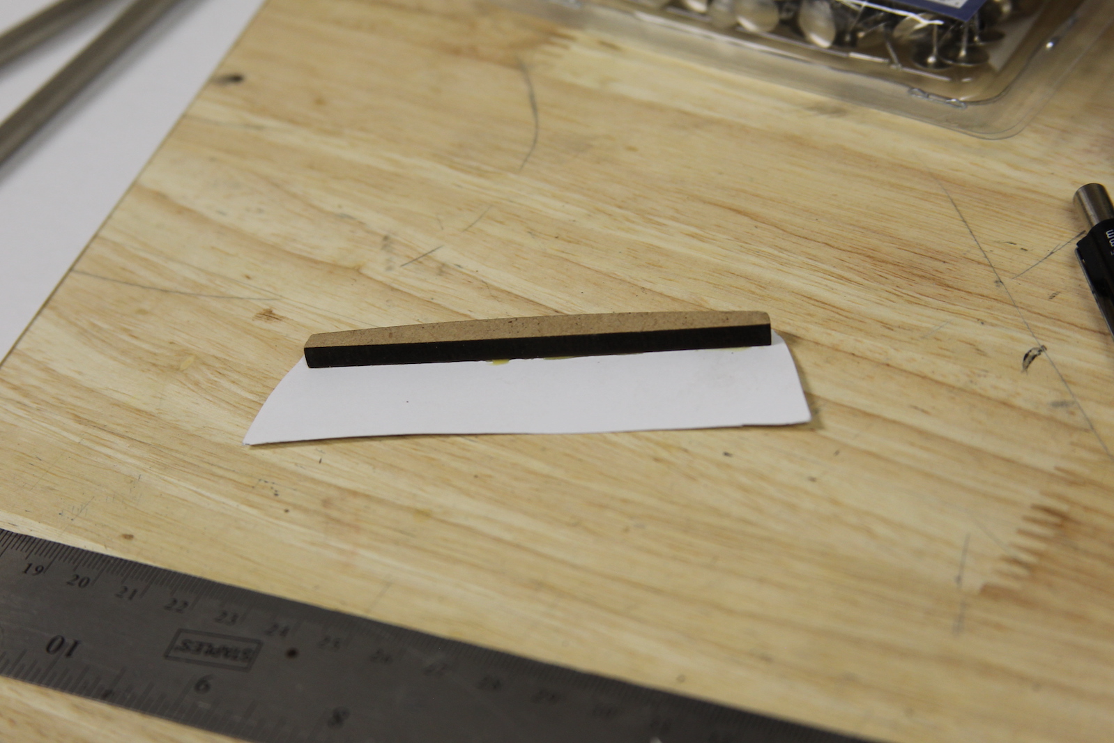
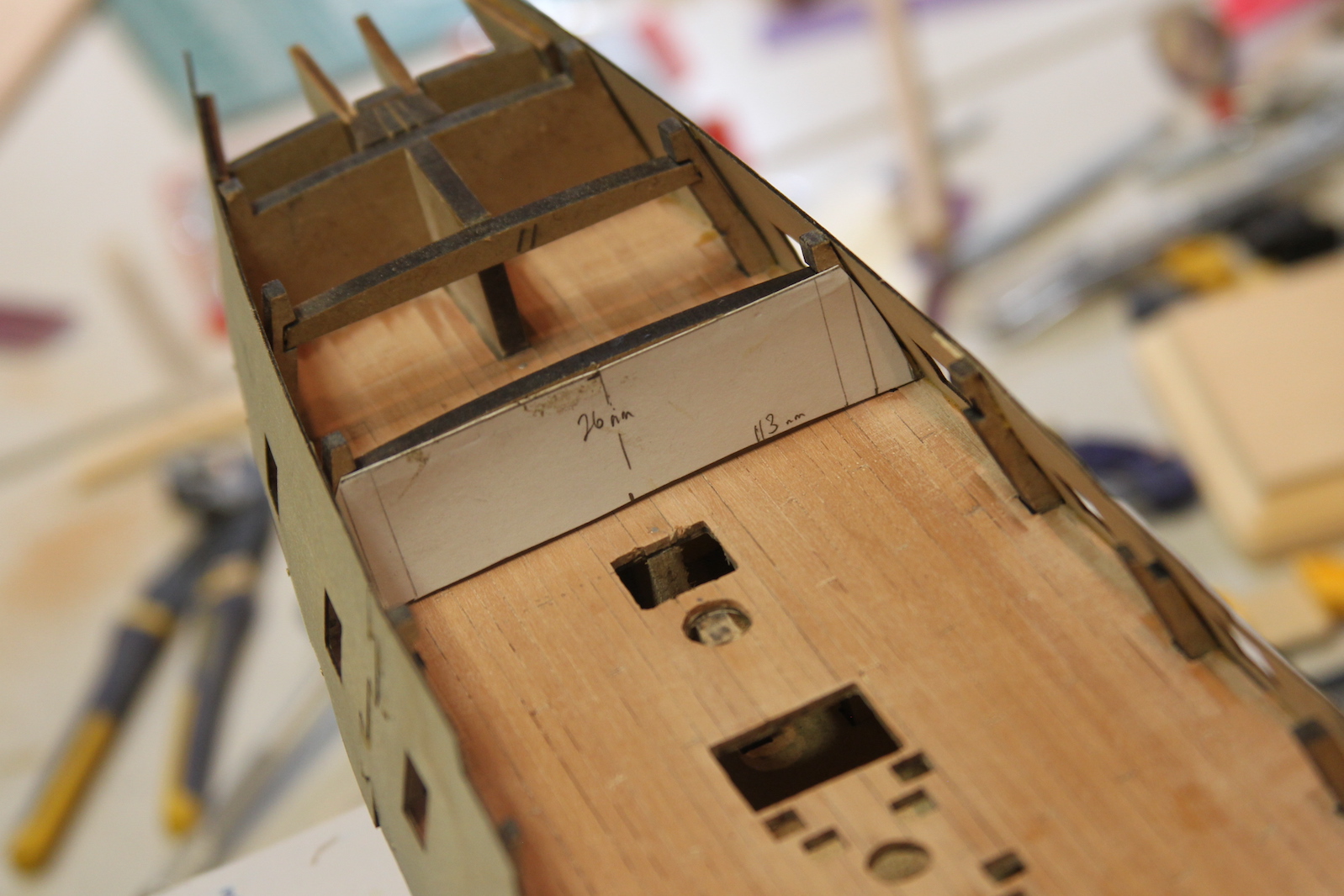
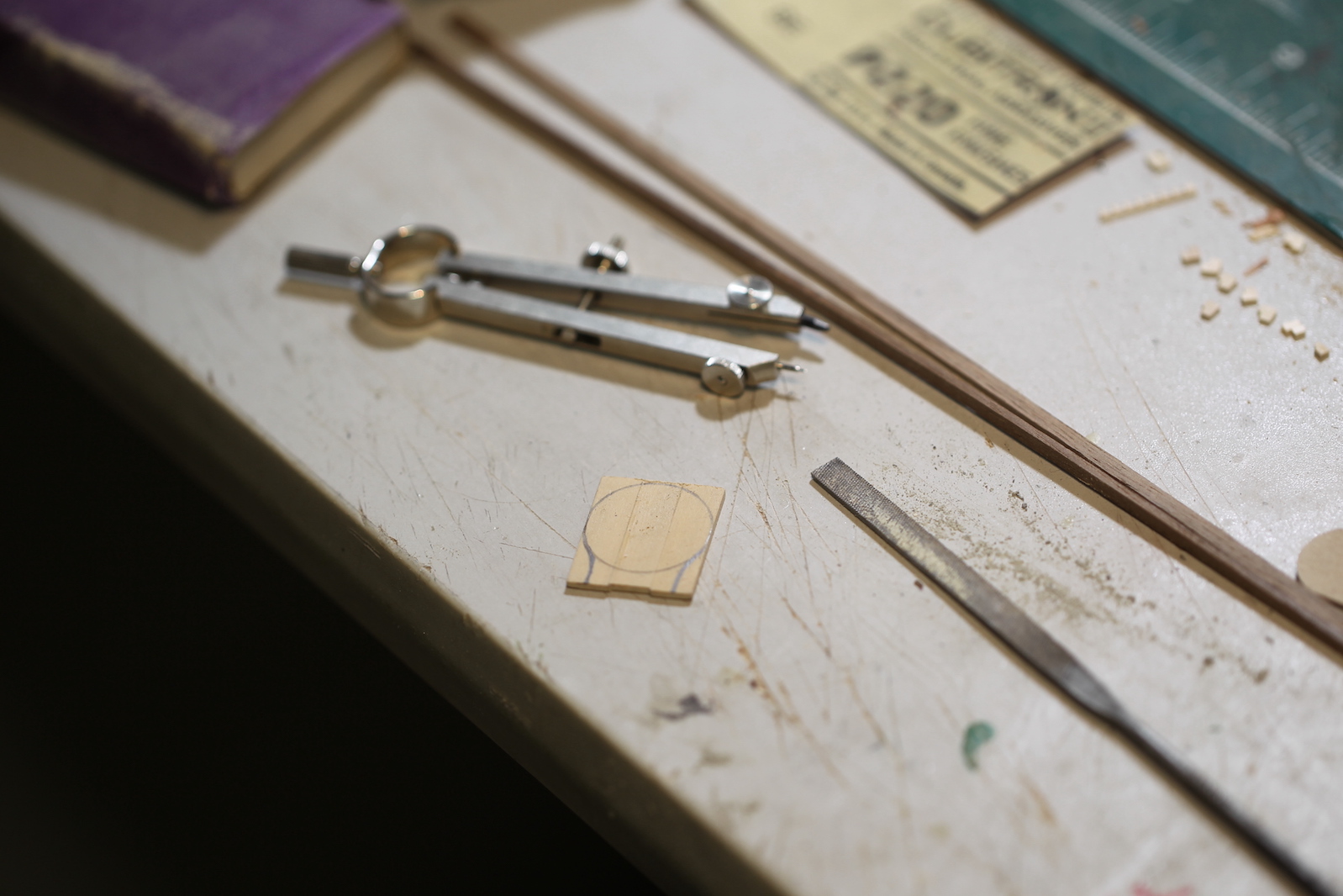
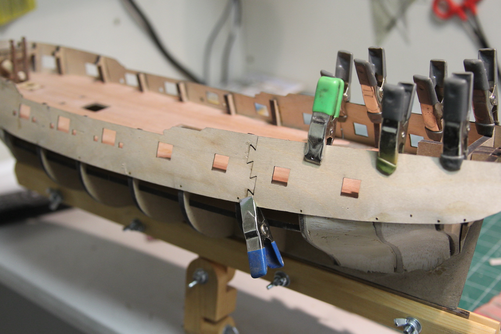
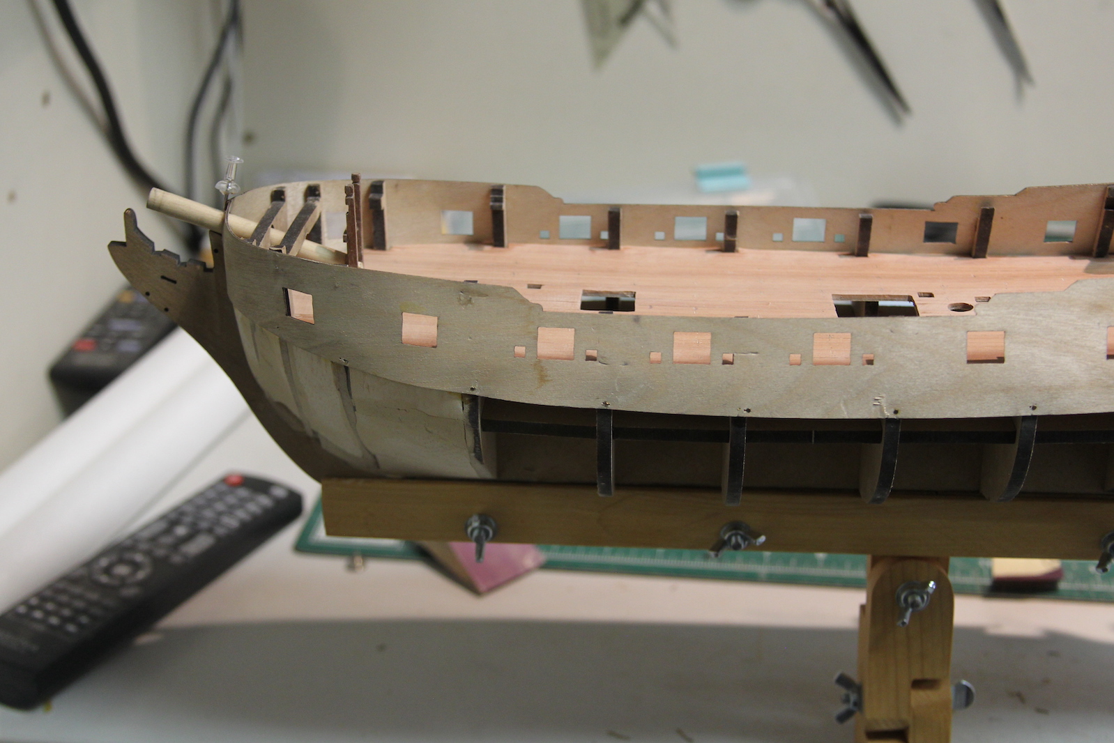
When I got to the final middle section I realized a couple of things – I botched the measurements at the stern and didn’t taper correctly. I was thrown off by the “L shape” and didn’t get the math right.  This lead to a pretty wonky looking section that needed to be filled.  So I used cardstock to take a template and try and measure out what needed to be done.  In the end, it was pretty clear I was going to need a stealer regardless.

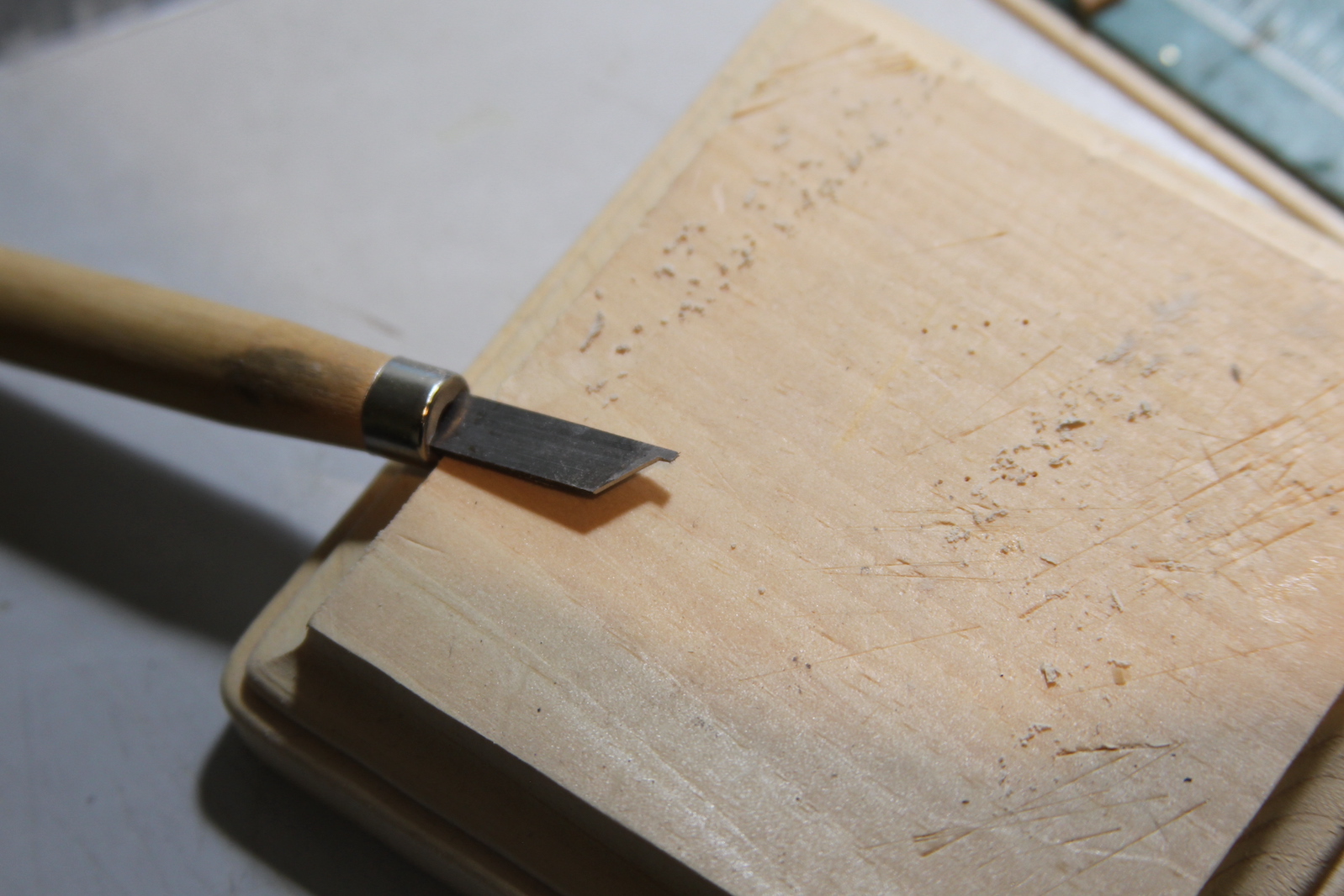
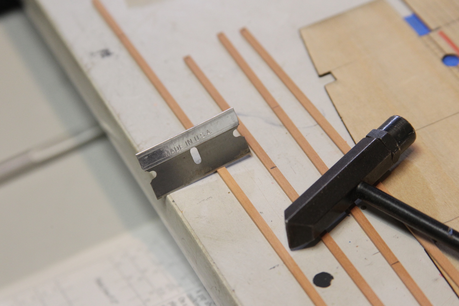
My method for the stealer isn’t really historically accurate, but I still think is a pretty functional way of handling my botched math.  I ensured that planks didn’t come to a sharp taper, and basically did a combo – split stealer – kinda deal to fill the remaining section. I started by gluing two of the planks together to create a wider double plank.  Then I cut off the ends to create the same kind of butt that I use in a more ‘traditional’ stealer in the stern section.  I traced out what needed to be filled then put a brand new blade in the x-acto to cut out and match the section to piece I created.

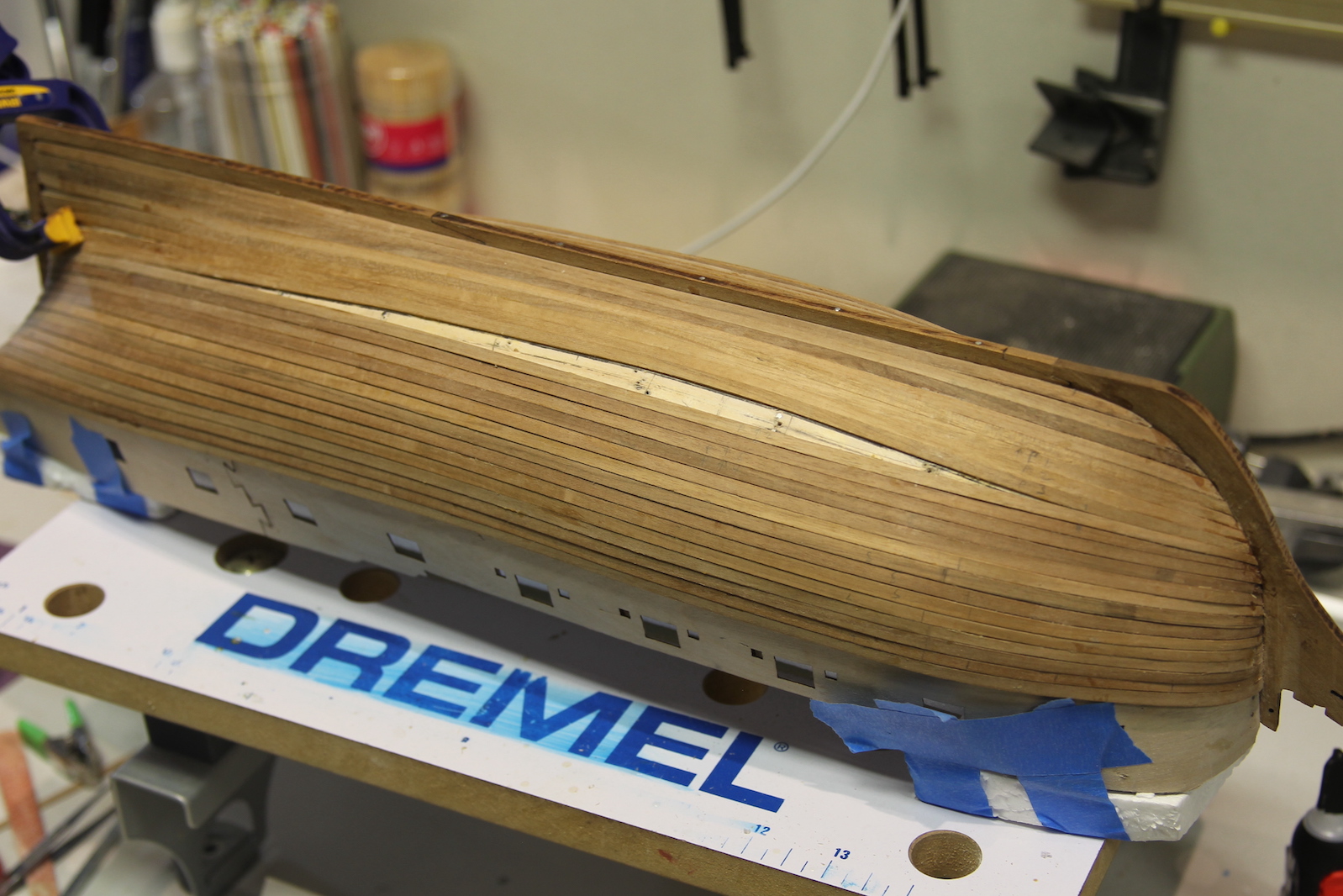
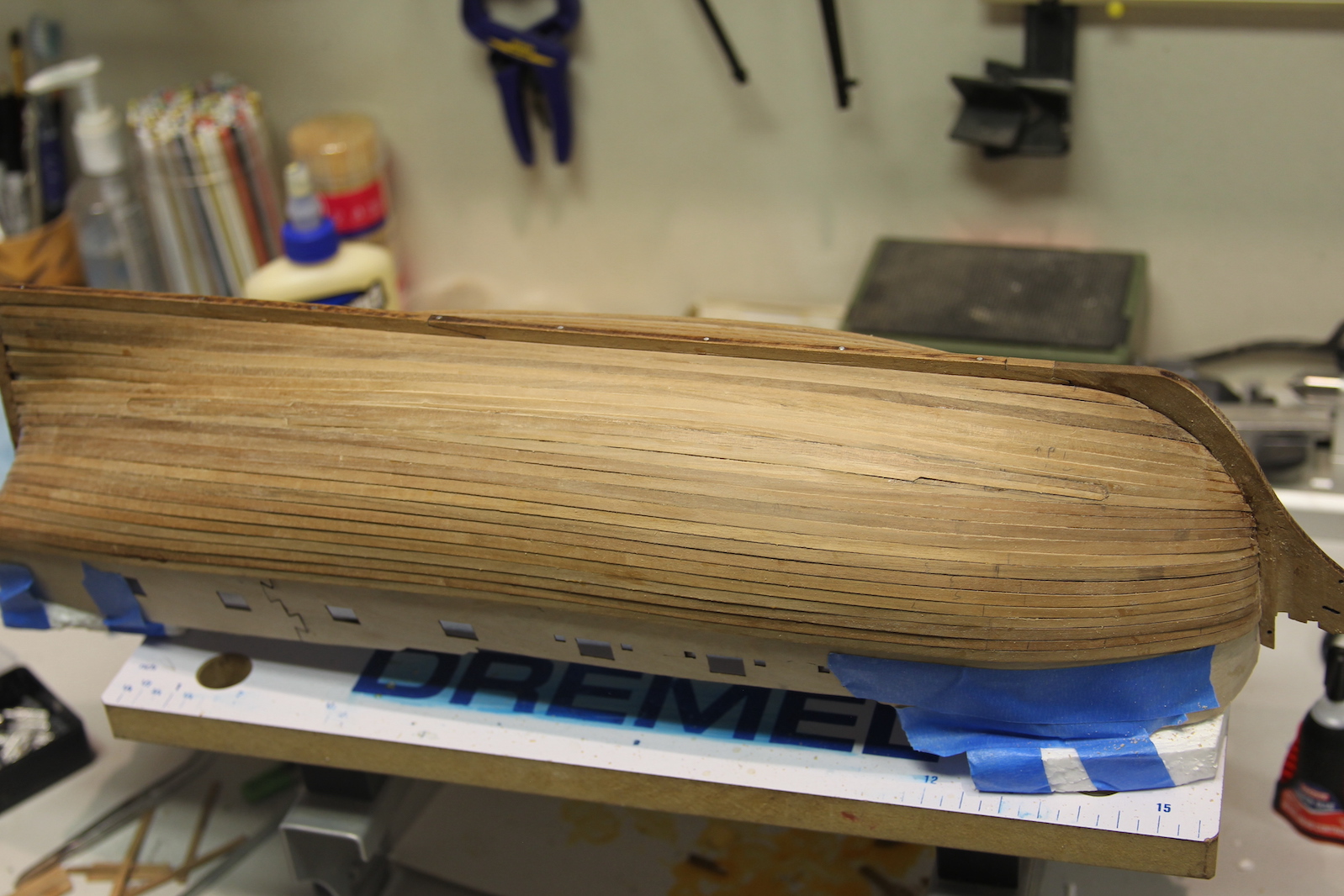
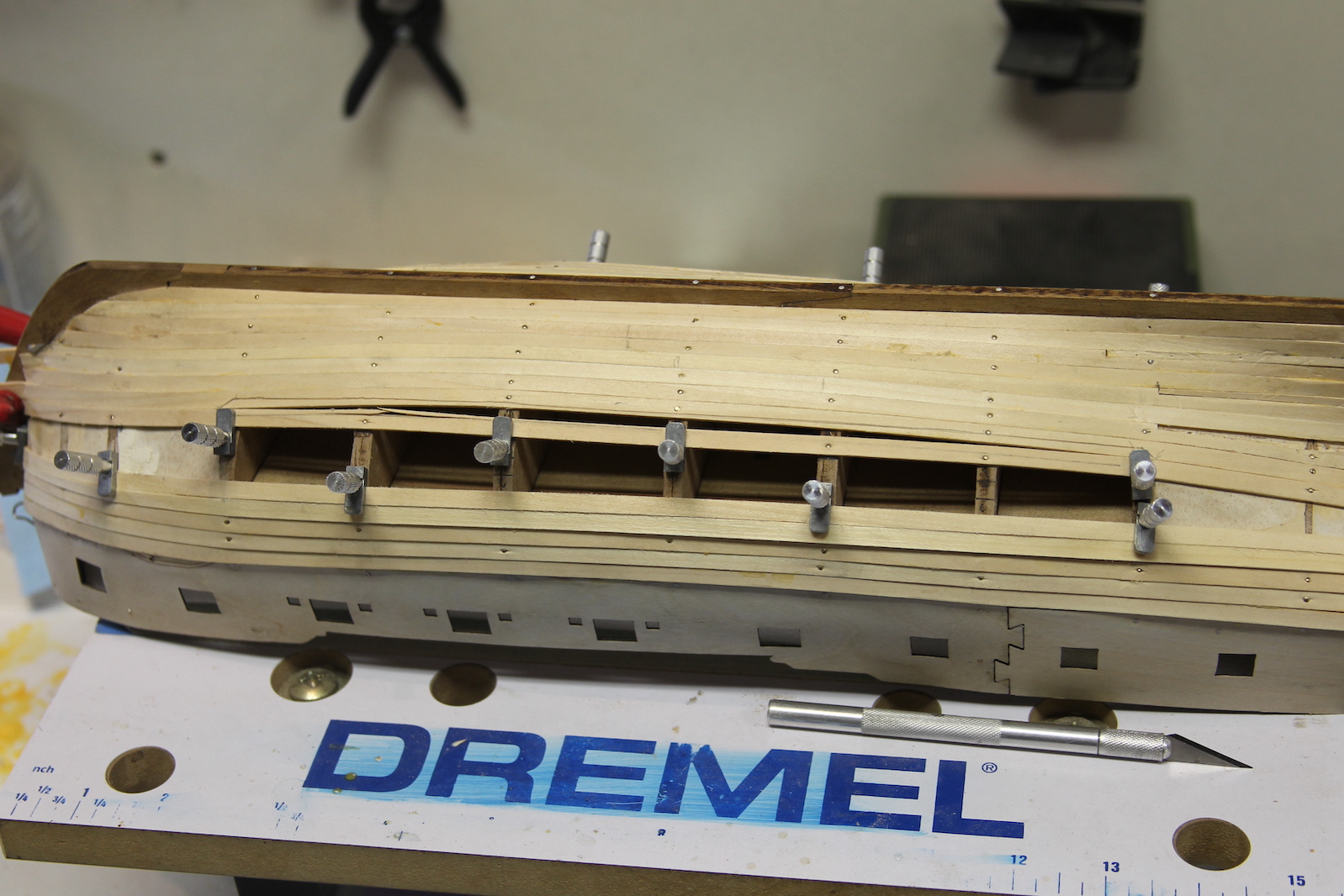
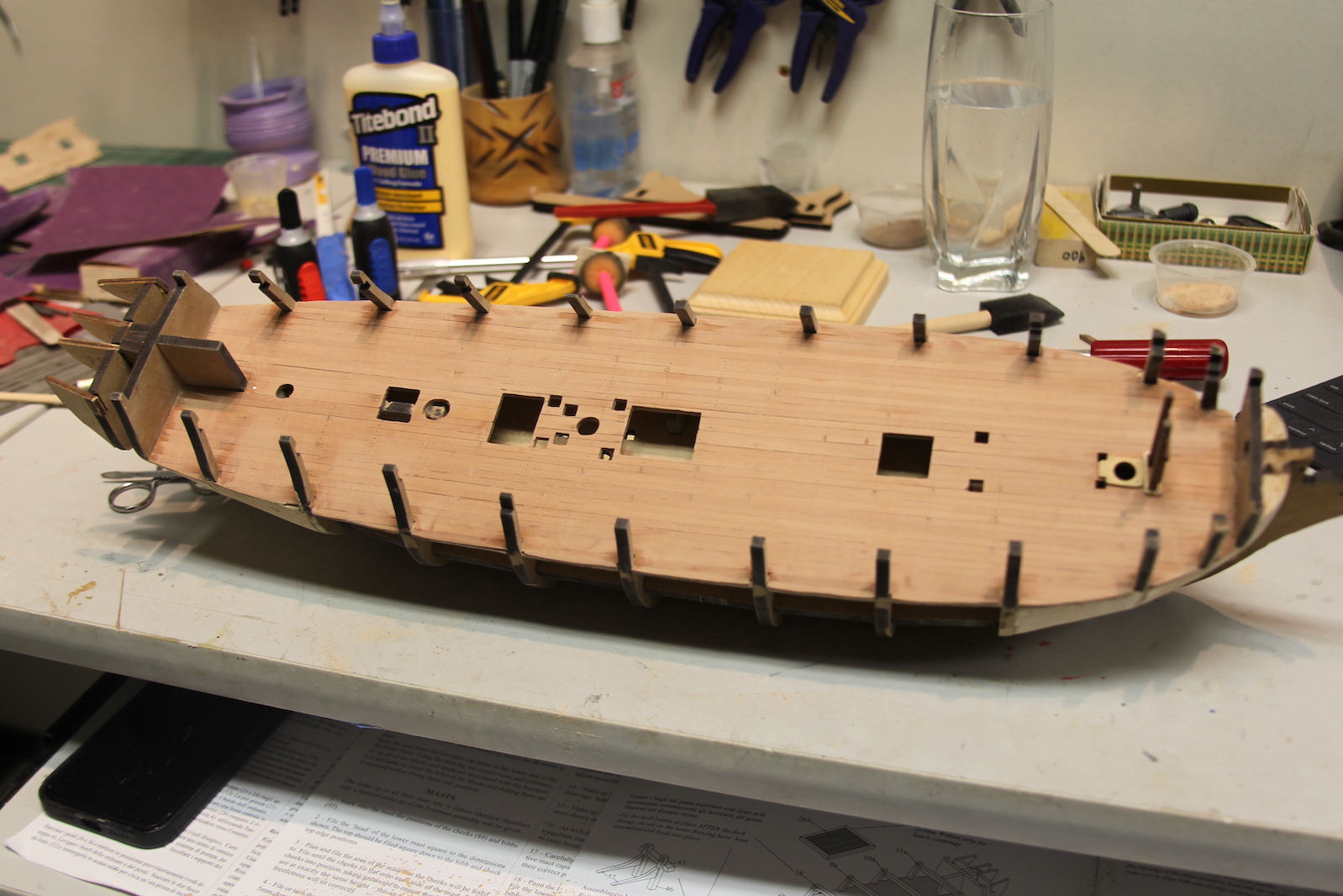
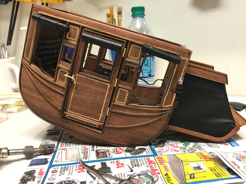
    Filling in the stern stealers rounded out the second layer.  

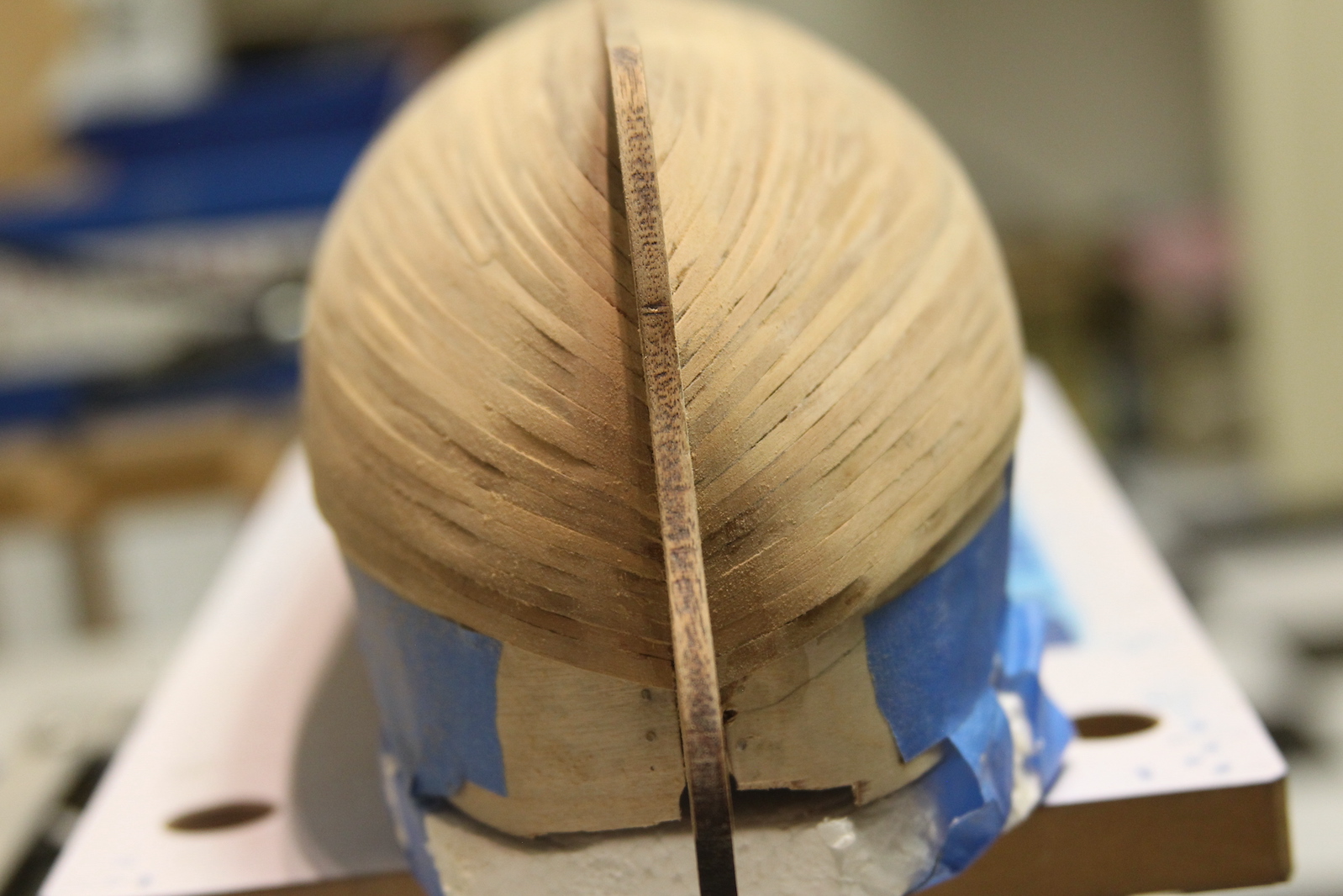
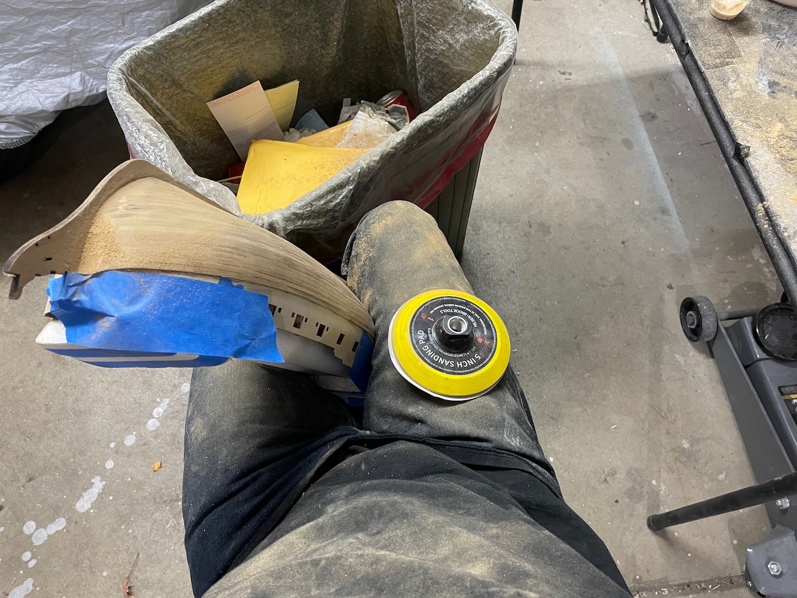
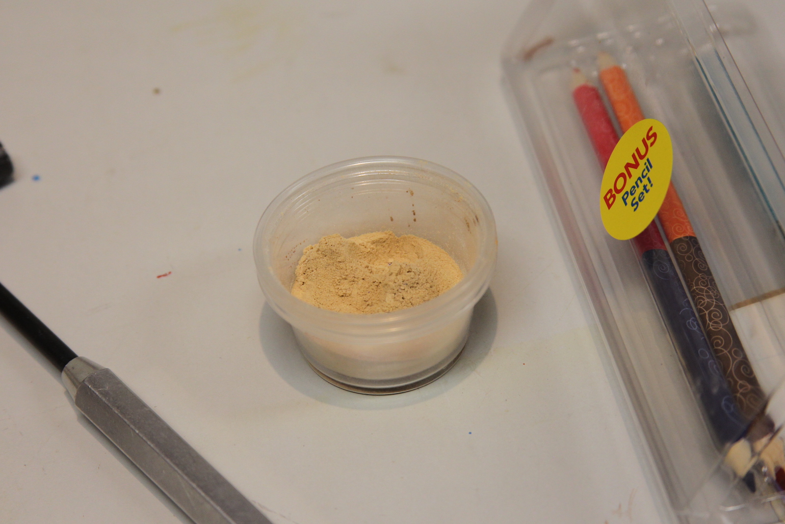
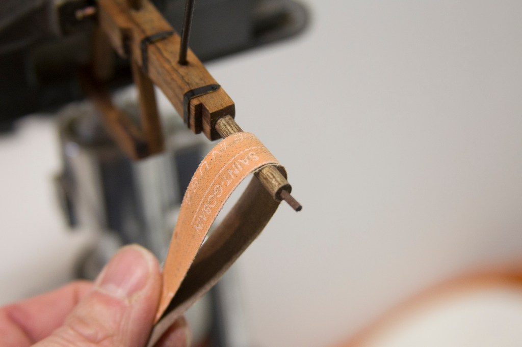
Next steps are all about sanding. Using increasingly fine sand paper as you go. I like to use a 5 inch sanding circle for a circular sander even though I’m doing it by hand because it’s easy to hold, easy to switch out the velcro sandpaper, soft enough to have some ‘give’ over the hull, and still precise enough to get into the spots I need to get to – like along the keel.. I use thin wood glue to fill in any gaps that appear, and then sand over it so the sawdust fills in the gaps and provides a similar enough color. At the end of the day it was one of my better planking jobs. Going into this I’d briefly flirted with the idea of not coppering the hull – but there ended up being a few too many flaws so I’m going to go ahead with the copper.

Lower Deck Fixtures – Cisterns

   As I’ve mentioned before – the deck fixtures are a pretty important aspect of the build for me. When someone comes along and takes a look a the ship, they inevitably start leaning down and taking in all the tiny pieces and parts. Now using the parts that come in the kit is just fine – after all chances are the observer really isn’t going to know what they’re missing. But taking a little extra time and trying to get accuracy on deck fixtures pays off dividends to be sure.  For Peg – while the Capstan at least basically looked like a capstan – the cisterns (or water pumps) really leave something to be desired.

   To over simplify, the cisterns have long pumps that extend into the belly of the ship’s hull to pump out any bilge as sailors pair up to turn the cranks. 

    I went back to the “Fully Framed Model” series to get some inspiration – as well as some really nice pieces done by other ship builders. First, I measured out the amount of space that we have between the mast and the grate and it’s limited at best. Not much room to play with there.  I started with my leftover boxwood strips to frame out the basic boxes. I use boxwood because it’s a nice dense wood that is perfect for carving small parts without leaving the wood ‘hairy’ and sands smooth really nicely.  I added some framing and feet, leaving a little extra space in the front of the pump for the doorway that opens up for the pump dale (where the water drains out onto the deck then ultimately through the scuppers (where water drains off the deck over the side. Then I carved out little doors that are used to close off the pump when it’s not in use.

  The pumps are fitted on the deck to see how they’ll line up with the really limited space between the grates and the mast partner. Then, it’s on to the chain cover. I glued together more boxwood pieces to create a sizable piece I could carve out and sand into a half circle. One the bottom of the cisterns are two pump drains. In a real ship this run all the way down into the hull so they suck up any bilge. They’re represented here by small circles that are flush with the deck.

  As I mentioned, the pumps themselves are worked manually with a crank (see below) that is attached to and through columns and bitts on either side of the cisterns. These pillars are pretty bland in the kit as well, but I used those as templates to create some that are a bit more pleasing to the eye but still functional. The pillars are carved out of mahogany then turned on a lathe must the same as a modern table leg – except way smaller of course. Mounting holes are also drilled into the posts which will hold the crank using my snazzy new miniature drill press from Micro-Mark.  

   The cranks themselves are cut from of a 1mm brass dowel. The cranks will run through the pumps (attached to a chained crank inside the pump on a real ship) and then mount to each of the posts. After the lengths of the bass are measured, they’re cut up and attached using metal braces. So – my first attempt at this endeavor of attaching the cranks to the braces was by drilling a .5 mm hole in each end using the drill press.

After burning through about 4 mini drill bits of varying strengths, I gave up in failure and went back to the drawing board.

I’ve seen other folks use silver soldering with this kinda thing, but I have no experience in that regard. After reaching out for some advice from the Model Ship World forum of which I’m a member, I ordered some basic silver soldering supplies from a jewelry making website.

My first attempts at silver soldering were actually pretty successful.  What was conveyed to me end up being pretty true – the most difficult part is finding ways to hold the tiny pieces in place as they’re soldered.  The green stuff in the syringe in the back of the photo is flux – this is applied first and heated up. Then the silver solder paste is dispensed using a different syringe with a hypodermic like needed opening.  Only a tiny, tiny bit is used. Then the torch is applied again until the paste turns to silver and melts into the connection.  All sanded out the end product looks pretty good.

I measured out all the distances between pumps and pillars on the deck then dry fitted everything in place. Afterward the crank is blackened. There will be some final touch-ups when it’s all mounted in place for real-sies…

Planking the Hull – Layer 1

     Like many contemporary kits, the Pegasus is a ‘plank on frame’ ship; which means the bulwarks are lined up along a keel (see previous post), then the planks are mounted along the bulwarks. However, the planks do not necessarily line up ‘straight’ along the bulwarks because a ship’s lines flow along the hull to create efficiency as she sails through the water. Obviously the shape and flow is different in the bow of the ship vs. the aft of the ship. This means that the planks need to be ‘shaped’ appropriately to not only sit flush agains the bulwarks, but so they line up against one another consistently along the hull.

    This (at least for me) is a very challenging part of the build. Fortunately, the Pegasus (like many other kits) is double planked – which means you lay down a solid planking to create the foundation of the hull, then an additional – usually thinner and more decorative layer.  Obviously ‘real’ ships only have  single layer of planking. But, the double plank method allows for some errors to be made on the initial layer that are covered up.

    That said – it was/is important to me to get the first layer as close to accurate as possible even though it’ll be covered up. This does a couple things: it makes it much easier to smooth out the hull and get the lines of the hull correct and subsequently requires a lot less sanding, etc.  It also makes it much easier to lay the second layer and line up the planking that everyone will ultimately see.

    Luckily, there are a handful of tutorials and training guides for planking the hull from some of the foremost model builders in the world – and I was happy to make use of them. Ultimately, the planking process is slow and deliberate and taking any shortcuts inevitably leads to mistakes.

  So here we go: I measured out the plank sizes and divided the hull into four sections.  I used some old pin-striping tape to mark.  This allows one to better count the number of planks needed, differentiate the differences between the bow and the stern, and determine the amount of tapering needed. Then, lo and behold I actually laid the garboard strake – the first plank along the keel of the ship. Each planked needs to be measured and placed individually – which is a slow process.  First, you approximate the length, then soak the plank in water until it’s fully absorbed. Then, you attach the plank to the ship giving it the shape it needs as it dries and forms to the shape of the hull.  

 The shape of the bow and stern are also quite different when it comes to the curvature of the plank. If you try to curve it along the bow too much, the plank pops out from the hull and is no longer flush.  It’s one thing to bend a flat piece of wood along it’s wide edge, but curving it along the short edge is an other thing entirely. This requires a delicate touch and in ship building is called “spiling’ the plank.  To accomplish this, I soak a plank and then curve it as much as possible prior to it’s splitting point and clamp it down to drive. I then mounted it to a piece of wood to create a ‘jig’ I can used to replicate the process.

   The jig allows me to spile a couple of planks at a time. Once they are dry with a proper curve, they’re much easier to shape against the hull as they now lay flush. You can tell by the different color of the planks which one is still wait waiting to dry against the form of the ship. 

    I’ve also decided with the first layer of planking I’m going to go with stealers – especially since I’m not cutting my own plank sizes, but using the kit wood.  With traditional planking one would cut/rip strips of wood to match sizes as the width of the hull narrows and the bow and widens at the stern. When using strips that are all the same width (as I am here) – ‘stealers’ fill in those gaps. The gaps are most apparent at the stern of the ship against the stern post. To fill these, I use card stock to cut and measure the size, then the card stock becomes a template to cut a plank. Each gap is unique, so this is done with each one at a time.

 With the measuring, soaking, forming, drying, measuring again, and glueing process – planking the hull is pretty slow and deliberate taking many days. Which is part of the reason the time is broken up by working on deck fixtures at the same time. I work the planking two fronts – from the keel and from the gunports.  The shape of the top and bottom of the hull are much different, so requires specific shaping. Then, ultimately the planks meet in the middle. Now – theoretically – if you’ve measured perfectly the middle should be easy to fill with full size planks.  That’s never happened for me – so once again I use stealers to fill the gaps that inevitably occur.  Worth noting – stealers never end in a taper as that creates a weak joint, so they are either squared off or end in an arrowhead like point.

  Another tricky part of the planking is the curvature of the stern at where the transom and the stern post meet. This requires a specially shaped planked that has to be measured and cut.

 Once the hull is completely filled in, there’s lots and lots of sanding to be done until it is smooth.  There are almost always (once again, at least with me) small gaps that are filled with either wood filler (if they’re large) or a mixture of glue and sawdust if they’re small.  Fortunately this time around, the few gaps I have are small enough to fill with the latter. A sharp eye will pick out the stealers in the middle of the hull.

  Next steps from here are a whole lot of sanding.  Although it borders on sacrilege to the purist ship bhilders out there,  I gave it a first pass using my really cool Dremel/rotary tool extension and a 60 grit tip on slow speed.  The extension allows you to hold it like a pencil and really lightly and specifically cover certain areas that need emphasis. The key is to get the planks that overlap in the above pictures evened out without sanding too much and going right through them.

    After I evened out the hull in general terms, I gave it more traditional sanding with 150, 220, 400, and 600 grit. There are a few slight gaps that I filled in with glue/sawdust (which is why they show up a little darker) or “Wonderfill”.  The key is to even out the port and starboard side as much as possible so the sweep of the hull is mirrored on both sides. 

   Next steps are to carve out a new rabbet line (where the second layer of planks will meet the keel and stern post) and then line out the second layer with a pencil.  Being able to draw out the schematic directly onto the hull will allow me to more accurately measure the taper and (possibly) stealers for the second layer. 

Lower Deck Fixtures – Stove

The ship’s stove is one of those great little elements that will be really challenging to see, but is totally worth it to me to get right.  My version of the stove comes directly from David Antcherl’s book on Swan Class ships. Some folks have recreated this stove out of metal, but I relied on the medium with which I am most comfortable – wood.

 I began by carving out and putting together the basic frame of the oven, then I needed to measure it’s scale on the deck.  The stove barely fits between the bottom and quarter deck with the vent/chimney sticking through the upper deck.  In order to accomplish this measurement, I had to go ahead and trim the bulwarks so the upper deck would lay flat.

Once I had the basic size and shape figured out, I started adding the small elements of the stove like the side doors & hinges and the grates. I dove into my little trove of miscellaneous little scraps and cut and shaped brass strips left over from other builds – mostly the Stagecoach I built for Sharon.

There are a couple of really specific pieces for the stove – the grate and also the hooks that hold the rotisserie bit on the front of the stove.  This is where it’s really handy to have built other ships – especially, in this case, Chuck’s USF Confederacy. Not only is the Confederacy also a 1/64 scale, but there were a plethora of extra laser cut pieces.  So I looked through my handy stash of extra bits and found just what I needed.

So… this is just a paragraph and a couple of pictures here, but this represents a solid three days worth of work in between setting planks on the hull to dry to shape.  After it was put together, I hit the stove with a layer of flat black, then a coat of an enamel metal-izer. As an additional touch, I added the brass rails and the little skewer

The vent that is in the stove above is removable and temporary. The actual vent needs to be inserted through the quarterdeck into the stove after assembly.  The realistic vent caused me quite a bit of consternation in determining exactly how to make it happen. It’s a very visible piece, so needs to be a good representation.    I’m not particularly adept at silver soldering, but that was pretty much the only way to go here. There really isn’t any kind of glue that works well for small metal bits – and JB weld or other epoxy is just super messy.  At any rate, I cut a small brass tube at a 45 degree angle, then reassembled it ‘backward’ to create a 90 degree vent.

This took me a few tries before I got it right, and got it to stick.  Each time I tried to either sand down the newly soldered vent parts or cut the vent to size, it would break off and I’d have to start again. The vent cover was a really tricky little bit.  I drilled to small holes into a circular piece of brass and used cut off straight pins as mounts.  Essentially, this all only “sorta” worked until I got tools to silver solder – then I re-did the entire vent with much better results.  Here is the second attempt.

After measuring to the quarterdeck I sized out the brass vent, then blackened it (which only partially worked). I ended up having to give it a light coat of matte black paint, then the same metalizer as used above. 

Lower Deck Fixtures – Doorways

    As I’ve mentioned, it’s always a little bit of an internal debate deciding how much to include on the lower deck when much of it won’t be ‘visible’ to the average viewer. Some folks who build this and other ships completely frame out the cabins on the lower deck, open up the transom windows (at the stern) so that all can be seen inside.  I won’t be going that far, but I did want to include enough to be realistic as some is also visible through canon ports, etc.

    To this end, I wanted to build the doorways to the stern cabins so there’s at least a backdrop stopping point to what is visible. I started with a firm template to measure out both the measurements and the deck slopes, and actually glued it to the beam. This allows me to me slide it in and out of the space until I’m ready to mount it.

   Pretty basic stuff after that, measured out some framing and doors.  I carved out some relief in the doors to give them depth and shape with some pin files in case someone gets frisky and tries to look down in there at some point. I gave that several attempts and this is about as straight as I can get those by hand.

Lower Deck Fixtures – Capstan

At the risk of REALLY falling off the nerd cliff – I have a bit of an unhealthy fascination with Capstans. The Capstan is a vertical axle (basically a rotating pulley) that multiplies force when hauling ropes and hawsers. It’s made up of a cylindrical base that runs through both the lower and quarterdecks. Each capstan has a drum head with holes where (when in use) bars are inserted and used to spin the base – wrapping a rope around the bottom and pulling up an anchor windlass or some other hawser.  

     The Capstan is always a pretty prominent and interesting looking deck fixture, so it’s important to me to get it as accurate as possible. While the Capstan parts that come with the Peg are alright, they are a little chunky.  So I consulted David Antcherl’s book on Swan Class sloops from the “Fully Framed Model” series for specifics.

     I used the Peg’s kit capstan as a scale guide, and some leftover boxwood strips to build out the parts. I channeled out the slots in two halves of the drum head then worked them together. I had to rig up a way to get it into the lathe, but that allowed me to even out the circle and also carve out a channel for the ebony parts. 

I don’t have much in the way of fancy power equipment in my shipyard (other than my nifty miniature Proxxon lathe), so I had to use some alternate tactics, including much use of pin files, x-acto knives, razor blades, and my handy dentist picks and tools. I also don’t have any ebony or super dark wood in my stash, so I used ebony wood filler which I loaded into the channel, then scrapped it flat and even with a razor blade. This particular wood putty doesn’t dry solid, so sanding it requires at least 600 – 1000 grit paper and a VERY light touch or it just smears.  I topped it all off with drilled holes and cut off pins as nails.

The ‘body’ of the capstan is made up of a series of ‘whelps’ cut into specific shape that strengthens the body of the capstan so it can endure the load.  I had to do each of the whelps individually without machinery. I split a couple of boxwood planks and glued them together, then filed out the shapes of the whelps  using various pin files. From there, it’s a matter of gluing them to the base, filling in the gaps and sanding it all down. Clearly I’m going to have to do some work with the framing to get this guy to fit, as well as connect the two capstans.  More to come on that.

The bottom capstan was relatively experimental, so I shored up my process for the upper capstan since it will be the one clearly visible on the upper deck (the bottom one will be visible – but obscured and difficult to see to the average viewer.  I used the same basic process as the bottom for the drumhead, and I put the whole thing back in the lathe to even out the diameter and carve out the channel for the ebony.  Lest you think this all went smoothly – my first attempt at the upper capstan turned out pretty crappy.  Too wide of an ebony circle, kinda thin, and overall just kinda crappy looking.  Back to the drawing board.

  For my second attempt, I used three sections of boxwood instead of two, carving out the capstan bar holes from the middle piece. This extra thickness gave me some wiggle room when it came to shaping the drumhead. I sacrificed one of my chisels to get the right sized notch for the ebony ring then used the same wood putty filler and smoothing the whole thing out.

Finally, after adding the whelps and filler pieces, I connected the two capstans for mounting later. For some perspective, the entire process of making these two capstans took around 15 hrs or so.

Lower Deck Fixtures – Grates & Mast Partners

    The deck fixtures are always one of my most enjoyable aspects on which to work. Putting in a little (or sometimes a lot) of extra time on these pieces really enhances the overall build as they often stand out to the viewer.  Although the deck fixtures included with the Peg are pretty decent, they still represent an opportunity to add some realism.

   The grates are pretty straight forward, and the grate pieces that come in the kit were easy to work with. I did pull out my own walnut pieces for the ‘coamings’ that frame the grates to get a little more shape to them. Otherwise putting the grates together is relatively standard.  Personally, I like to group the number of grate linings that I need then cut them with a jeweler’s saw so I have them as even as possible.  This is a delicate process because the little ‘nubs’ have a tendency to snap off pretty easily.

    Some folks may not realize that masts of the ship were not bolted to anything specific on the ship. As you might imagine, while under sail (particularly in rough seas) there was a great amount of movement and strain on the masts. If the masts were firmly attached to the ship’s frame, this strain would tear the ship apart from within the hull. So, instead, the masts were held in place by partners and wedges. The partners framed the mast into the deck itself and the wedges formed a band around the mast.

    My mast partners are pretty basic and made by gluing a few pieces of boxwood (a very dense, easily carved wood) together, shaping the edges, sanding out the hole, and then mounting them to the deck. The oddly shaped little fella is the step for the Capstan.

Gun Ports

   Aligning the gun ports seems like a pretty simple process, but is crucial to the symmetry of the ship as well as aligning the cannon and other deck fixtures.  The pre-fabricated gun port templates not only set up that alignment, but they also set the stage for how the entire hull will be planked. 

    To get the gun ports even and accurate, I soaked them in water for a couple hours to loosen them up, then clamped them to the sides of the ship – careful to line up the ridges with the bulwark posts that extend up through the deck. Then I left them there overnight to dry in that fixed position.

    Then, I glue them along the sides using PVA (wood) glue along the posts and outside the deck and add nails into the bulwarks and posts.  I used a little bit of CA (super glue) on the inner posts just to hold the gun ports in place.  But these posts will be removed later.

   The pre-fab template comes in to pieces that link together toward the stern. This is kinda funky because there’s really nothing holding them together and very little space to adhere. So, I added a flat piece of wood behind the seam to bolster the joint.  I’m hoping it’s thin enough that it won’t interfere with planking – otherwise I’ll remove it and let the wales hold it in place as it’s planked.

When the hull is planked, so shall the gun ports – so some imperfections will be covered. But, needless to say the smoother the job here, the easier it’ll be to have a smoothly planked hull later. 

Deck Repairs and Bowsprit Bitt

    No build goes smoothly.  The key for me is to try and maintain my patience and not get in a hurry with any particular aspect.  Whenever I DO get in a hurry… something like this happens.  I decided to use a Dremel attachment to do a little deck sanding and save some time.  I clearly wasn’t careful enough, because the bit scraped and dug into the deck.  Oops.

     The silver lining is – pulling up a couple of planks and making the repairs also gave me the opportunity to resurface and smooth out the entire deck. 

     One common element of some model kits is that there isn’t much to the parts that are mostly unseen by the viewer. In other words – not a lot of elements that exist below the quarterdecks are included in these plans.  So, one has to make a decision as to how many of these elements should be added to the build.  My guideline tends to be – what can be seen through either the portholes, cannon ports, or through the deck grates.  

  Peg’s plans have a solid piece of material toward the bow of the ship that adds extra support to the quarter deck.  The Bowsprit itself is inserted into the bow and rests against this material.  In a ‘real’ ship, the bowsprit extends into the lower deck and is held into a place by columns that contain rigging bitts.  I’ve added these (and a couple other) elements to the lower deck.

    Once again – much of this will not likely be seen by viewers, but it adds the accuracy of the ship.

Back to the Hull Again

    Planking the hull is always the most difficult aspect of a build for me. Not only is it tedious, but it’s a challenging and precise endeavour that tolerates few mistakes.  Basically, the process entails soaking a strip of wood, bending it to it’s proper shape to run along the bulwarks, tacking it into place, then either drying it with a heat source (or letting it dry naturally), then gluing and nailing it into place.  It’s a one-strip at a time process that I have great difficulty getting right. The goal of course is to have smooth and consistent lines between the planks that can be sanded into an overall consistent and smooth hull.

    To this end – I’m a pretty big fan of filling the spaces between bulwarks with balsa wood so that I have more solid footing with which to form and mount the planks. I started out by marking and sanding down the bearding line (where the planks meet the stem), then filling the spaces with chunks fo balsa.

Then there’s just a lot of carving, cutting, and sanding until you get a smooth consistent surface.  Inconsistencies are filled in with wood filler, then more sanding. This is one of the messiest parts of the build (probably next to sanding the hull itself), and I kind of wish I’d taken a couple of photos of the hobby room and garage during the process.

Once I get a surface I’m happy with, I can remount the keel. I’ve always had some difficulty with a keel staying in place with just glue (regardless of the type of glue used).  So, in recent builds I’ve developed a technique where I drill a small hole all the way down through the keel into the hull, then use straight pins as mounting nails in addition to wood glue.  This seems to work pretty well, and is an important strengthener as the keel spends a lot of time in the wooden vise.

  This last photo is just a fun little sidebar – I don’t even remember where I got this soft styrofoam tubes, but they work perfectly to protect the deck when I have to have the ship upside down to work on the hull. An example of using whatever’s handy during these builds.

Planking the Lower Deck

  Mounting and letting the frame dry gave me an opportunity to plan out my deck framing strategy. I’m using 4 plank stagger based on Mondfeld’s book, as well as Danny’s planking example on the lower deck of the Vulture.   Since I tend to get easily confused – I like to draw out the lines on the false deck so I stay consistent.  I’m planning out 90m planks based on the scale, then I color code the stagger.

    As with my other projects, I like to go with a ration of about 70% accuracy and 30% artistic license. I try to keep the history consistent, but also feel a little like a ship’s Captain who may have personalized his ship a bit.  To that end – I have a fair amount of Swiss Pear left over from the Confederacy build, and jus loved the way it looked. It smooths out so beautifully and just adds a touch of class in my opinion. So I’ll be using it on Peg as well.

    As far as planking itself – I’m going to run a 1/8″ centerline “King” plank, then mirror each side with 1/16″ planks that run the length of the deck. It’s much easier to plank the length, then simulate the end butts with a few taps of a razor blade. 

    The treenails are always a bit of an issue and very much a personal choice. This time, I’m going to mark them with a thumb tack – double nails on the butts, and a single nail across the beams based on the size of the planks.  Planks less than 10″ were singled and not double nailed. Numbering the end of each plank allows me to lay them out and cut/mark all of them before I glue them down to the deck. 

    I’ll finish simulating the treenails by laying down some of my old school scene glue (from my train village building days) and filling it with fine sawdust.  I’ve always made a habit of collecting and saving the sawdust as it can serve a variety of purposes, including making a convenient filler.

Peg’s plans call for planking the lower deck prior to mounting it to the frame. The false deck (shown above with my color lines, etc) is split into two pieces to facilitate mounting – which is great. But, if I proceed that way, I have no means of mounting the king plank and spreading the rest of the patter outward from that. So – contrary to the plans, I found it much easier to planks the lower deck after it was mounted to the frame. I followed the pattern I laid out on the false deck, keeping in mind that I had to cut and shift the planks as I got near the edges. I briefly mulled over the idea of creating a waterway/gutter (a specific additional water tight plank along the edges of the deck) along the sides, but ultimately ditched the idea for the lower deck as it’s a fair amount of work that isn’t likely to ever been seen; and would prove challenging based on how the frames are put together.  Perhaps for the upper deck.

After the deck was fully planked I gave it a light sanding w/ 200 then 400 grit, then gave it a very light layer of wipe on poly to check and see how the treenails would pull out visually.

The lighting on the photos isn’t great – but I’m pretty happy with how the deck turned out.  A little crooked on some of my butted plank marks, but that was part of the reason for experimenting with this technique on the lower deck – I’ll refine the technique for the upper decks and hopefully have a cleaner look. Overall, I still love the color and feel of the Swiss Pear even though it’s obviously not an accurate representation of the decking from that period. I really think it’s going to make the deck fixtures and accessories pop. 

The Frame

   Welcome back to the Shipyard for another build. This time, it’s the H.M.S. Pegasus,

   The framework for the Pegasus (who I shall from now on refer to affectionately as “Peg”) is essentially the same as most frame on bulwark kits with a couple of exceptions by Victory Models.  Others who’ve build this ship have noted as well – the fabricated wood framing is so much easier to deal with that the plywood that comes with other builds.  The pieces all fit together wonderfully and require much less sanding and smoothing out.

    That said – there’s still plenty of room for adjustments. For instance – the instructions say that a rabbet line is unnecessary on this build as its double planked.  To over simplify – a rabbet line provides a ‘slot’ within which the planks will sit and then lay flush with the keel.  I went ahead and cut one in because in my experience it just makes things easier down the line.

    Other than that – lining up the frame is pretty standard stuff with one other notable exception for the Victory kit – they provide a solid lower decking that makes it easy to ensure the spacing between frames is tight and consistent.

H.M.S. Pegasus

If folks are familiar at all with the H.M.S. Pegasus, it’s the usually with the second iteration – a 28 gun sixth rate frigate launched in 1779. The 1779 ship was most notable for having Prince William Henry (who would become King William IV) as her Captain for a brief time.

The first H.M.S Pegasus (and the one featured here by Victory Models) was a 14-gun Swan class sloop launched in December of 1776.  She sailed to Newfoundland the following year – and subsequently sank in a storm losing the entire crew.  A bit less of an illustrious career.

Two key factors led to this particular build: I wanted to do an 18th century swan class ship from the English Navy, and I needed to build a ship for my youngest daughter.  Since there was no “HMS Unicorn” – Pegasus was a close second.

At any rate – welcome again to the Lehman Shipyard, and thanks for joining me on this journey in building the H.M.S. Pegasus.

1848 StageCoach

I decided to take a short break from building ships between finishing the US Frigate Confederacy and starting the HMS Pegasus.

A few years ago, our family took a road trip from Colorado to Washington state. We stopped at a great little western museum in Montana where my wife saw a beautiful little state coach replica that she fell in love with.  That following Christmas, I picked up a stagecoach kit that I promised to build for her.

That kit sat on the shelf for a few years, until I finally committed to finishing it the beginning of 2017.

After successfully transitioning the “Shipyard” in to an old west manufacturing plant, I got underway with this Artesania Latina 1/10th scale version of a stagecoach.

While the kit itself has come good pieces to it – the wood is pretty dried and brittle and difficult to work with. I’ve had to substitute a fair amount of pieces and come up with a number of “work arounds.”

Completed Stagecoach

Build Photos

1932 Rolls Royce

Pocher Models are some of the highest rated, most detailed models on the market. The company essentially began in 1966 when Arnaldo Pocher introduced a 1:8 scale model of the Fiat F2 130HP. The Company went on to produce ever more detailed models of motoring classics that included well over 2,000 and upwards of 3,000 parts.

I came across this 1/8th scale 1932 Rolls-Royce Phantom II on E-bay, and decided to give it a shot. It’s by far the largest scale model I’ve put together which lends itself to some great detail – however also the possibility of being able to more clearly see errors.

The Finished Model

Japanese Zero Fighter

1943

In 2017 my daughter and I took a return visit to Japan so she could see where she was born. While their, we visited the Japanese museum of history, which included an amazing and insightful look at World War II from the Japanese perseptive.

I picked up this Tamiya model as a companion to the F4 Corsair, as they were opposing forces in the skies over the pacific. Interestingly, the Zero was more susceptible to weathering and damage, which I tried to reflect in this build.

Glenwood Creek

In 2009 I put together a very small, very basic N-scale layout. It was my first foray into any sort of scale railroad project. While simplistic, it gave me a feel for the details and was quite enjoyable. As I mention in my HMS Pegasus build, there came a point between finishing the main hull structure and starting the rigging where my interest wained and an 18 month gap in progress ensued. After looking at a couple of my ‘leftover’ pieces, I decided to plan, architect, and build another N-scale layout to get me back in the groove of at least building something.

The layout is a 4′ by 4′ double track sectioned into three switchable segments with an additional ‘work yard’ section that can be independently switched. Two turnouts are switchable with another 5 manually switched. All of the electronics are grouped and connected with wiring harnesses that allow everything to be removed from the control panel. In addition, the entire layout is held together with cabinet latches on the underside and can be split apart into separate 2′ by 4′ pieces allowing it to be transported or stored.

The name “Glenwood Creek” comes from the small creek that runs through the length of the fictional village – which is a combination of my Pacific Northwest upbringing and one of my wife’s favorite places to visit in the mountains of Colorado – Glenwood Springs. I’ve included all of my four adult children in the layout, as well as a few fun little scenes that allow the viewer to come up with their own explanation or storyline.