Catheads

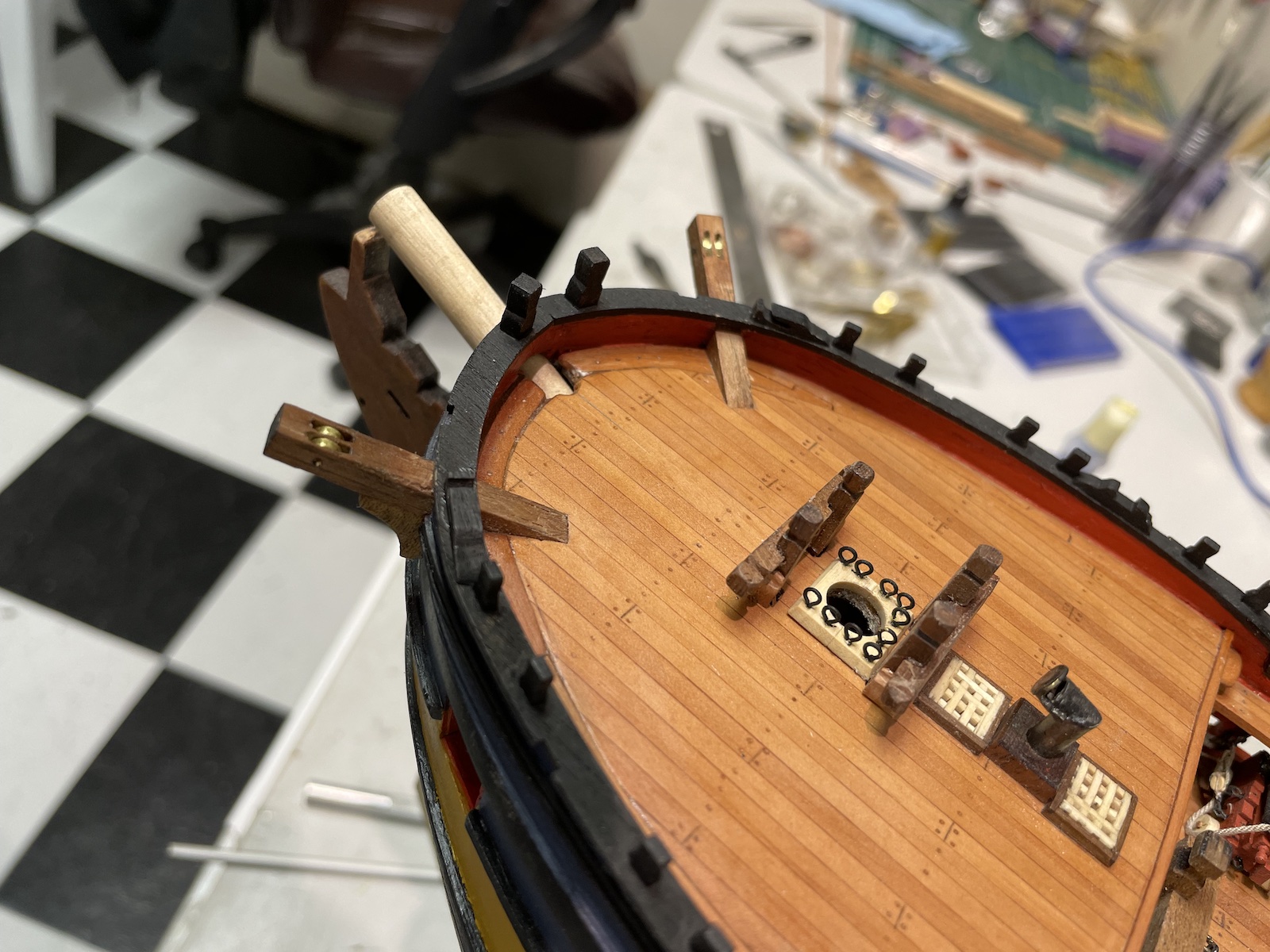
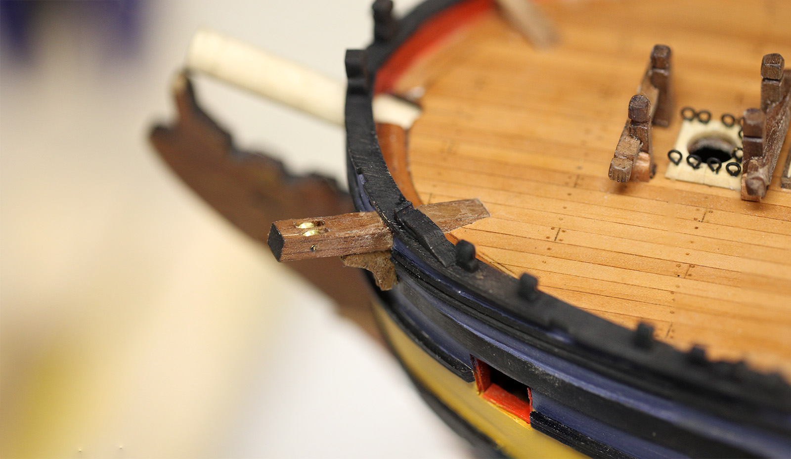
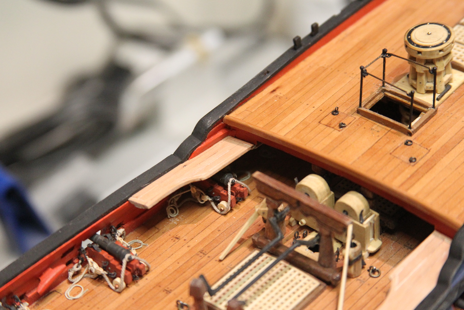
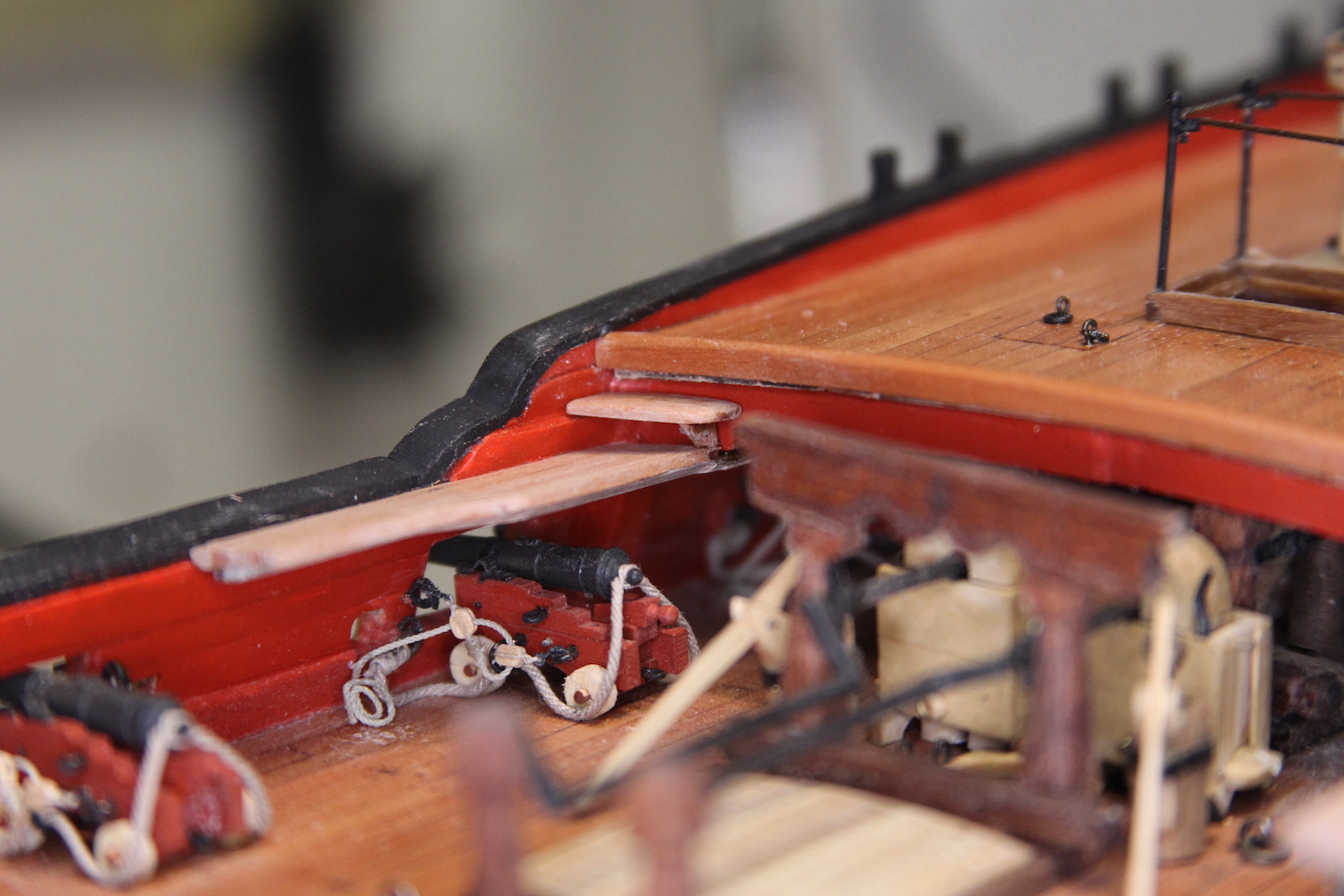
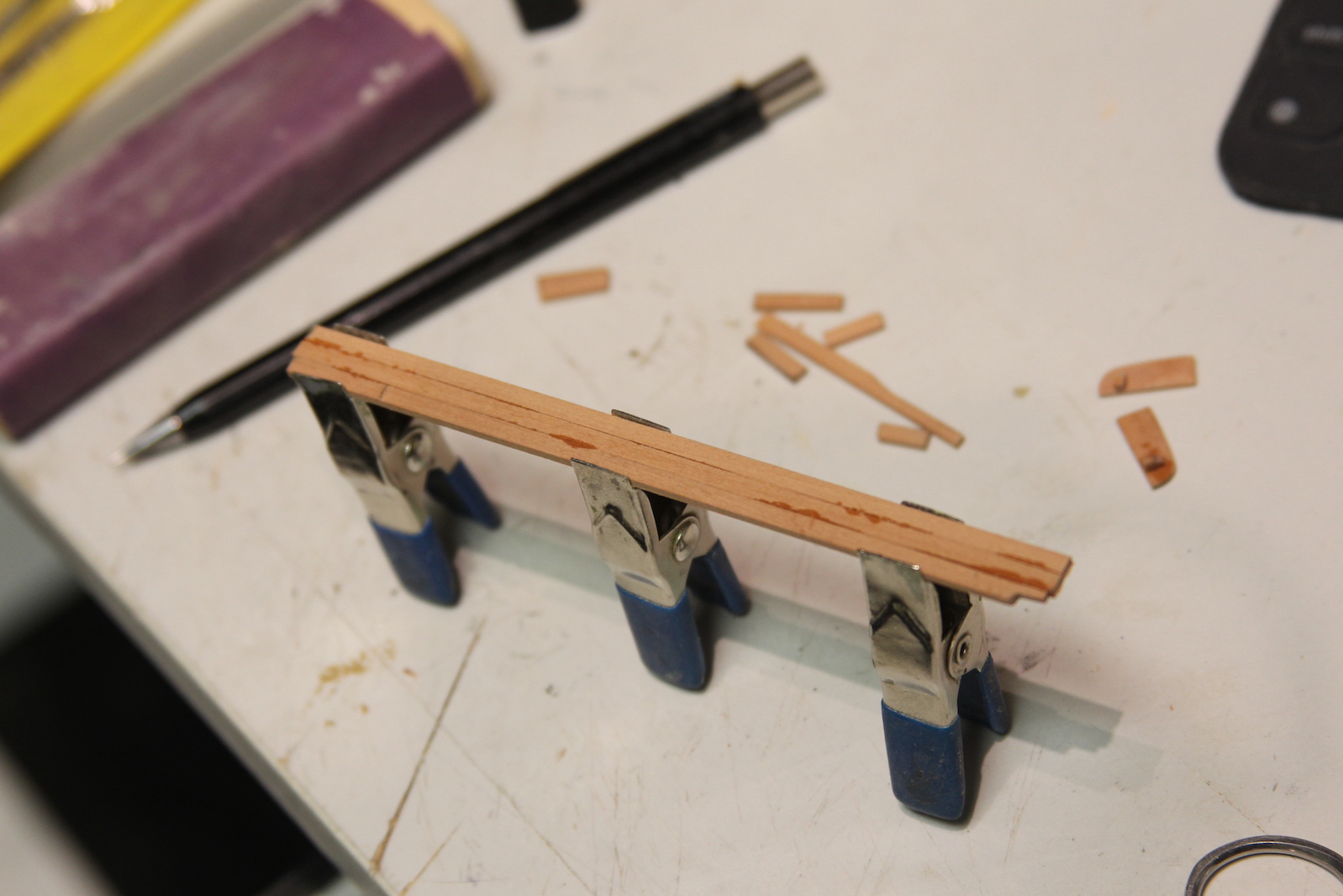
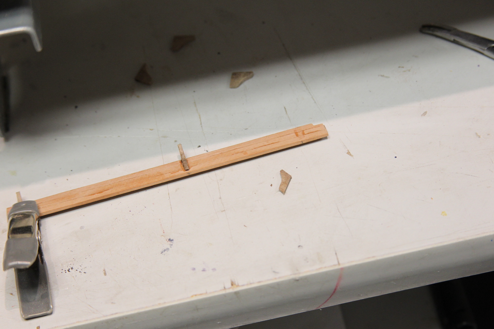
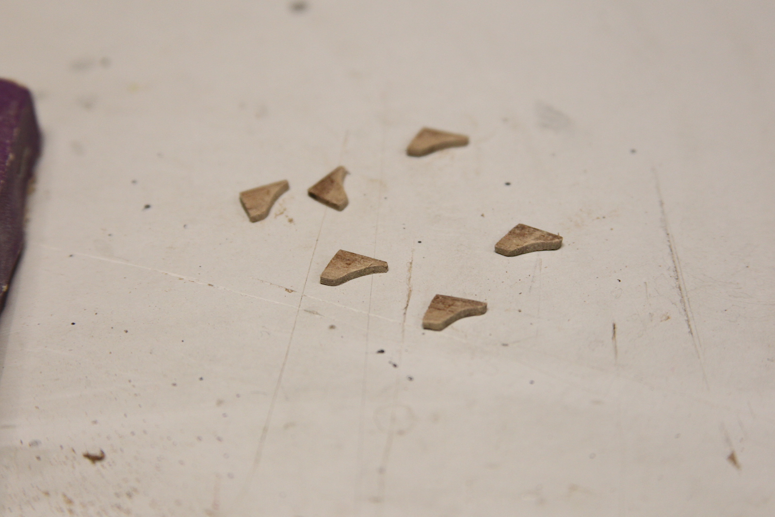
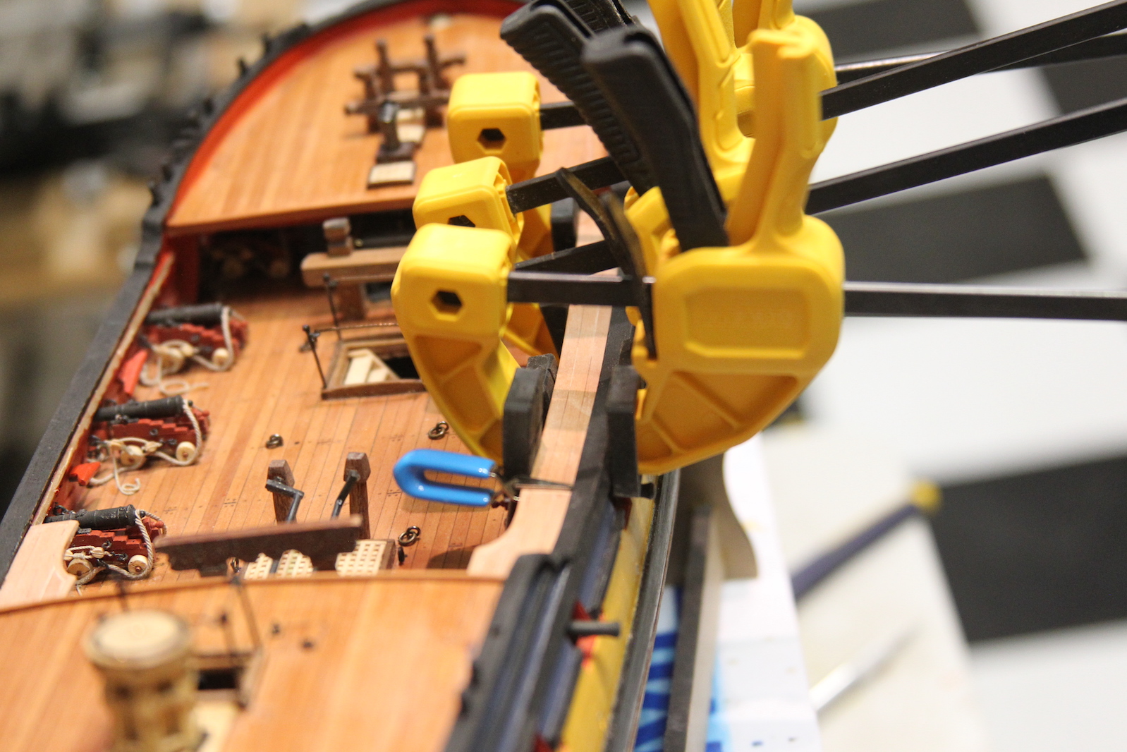
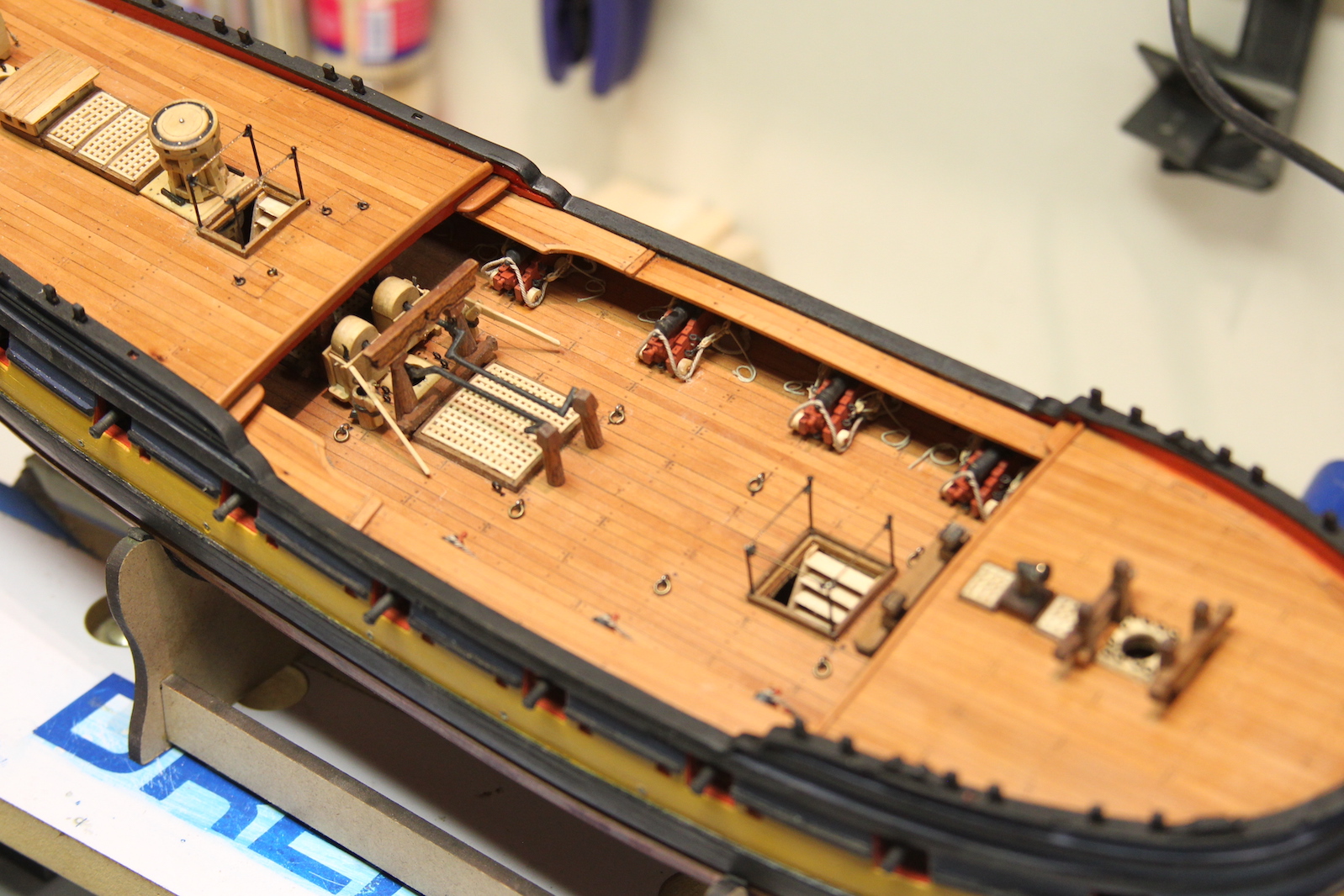
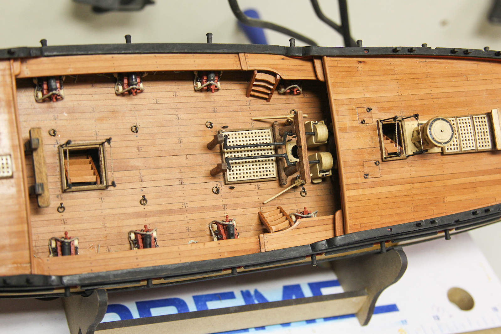
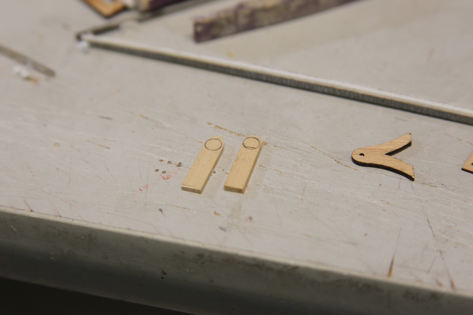
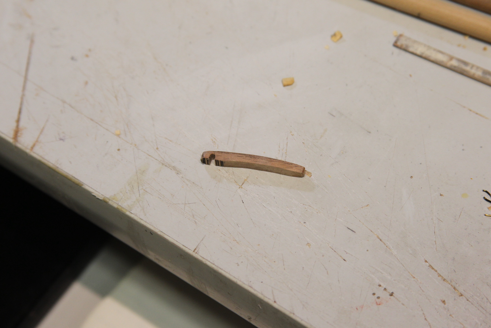
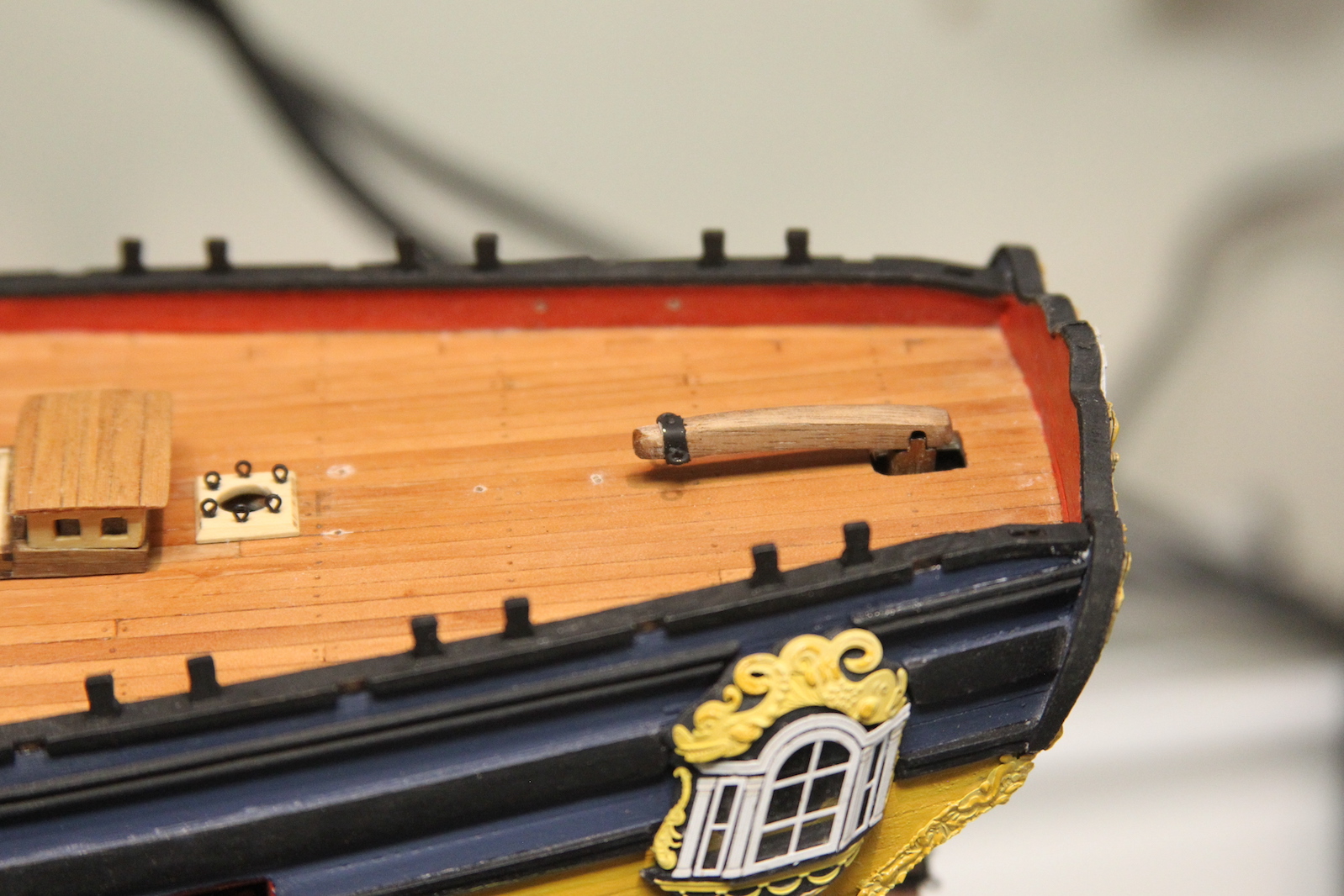
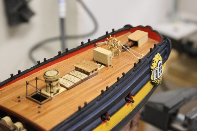
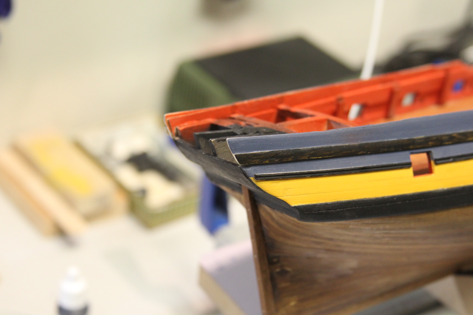
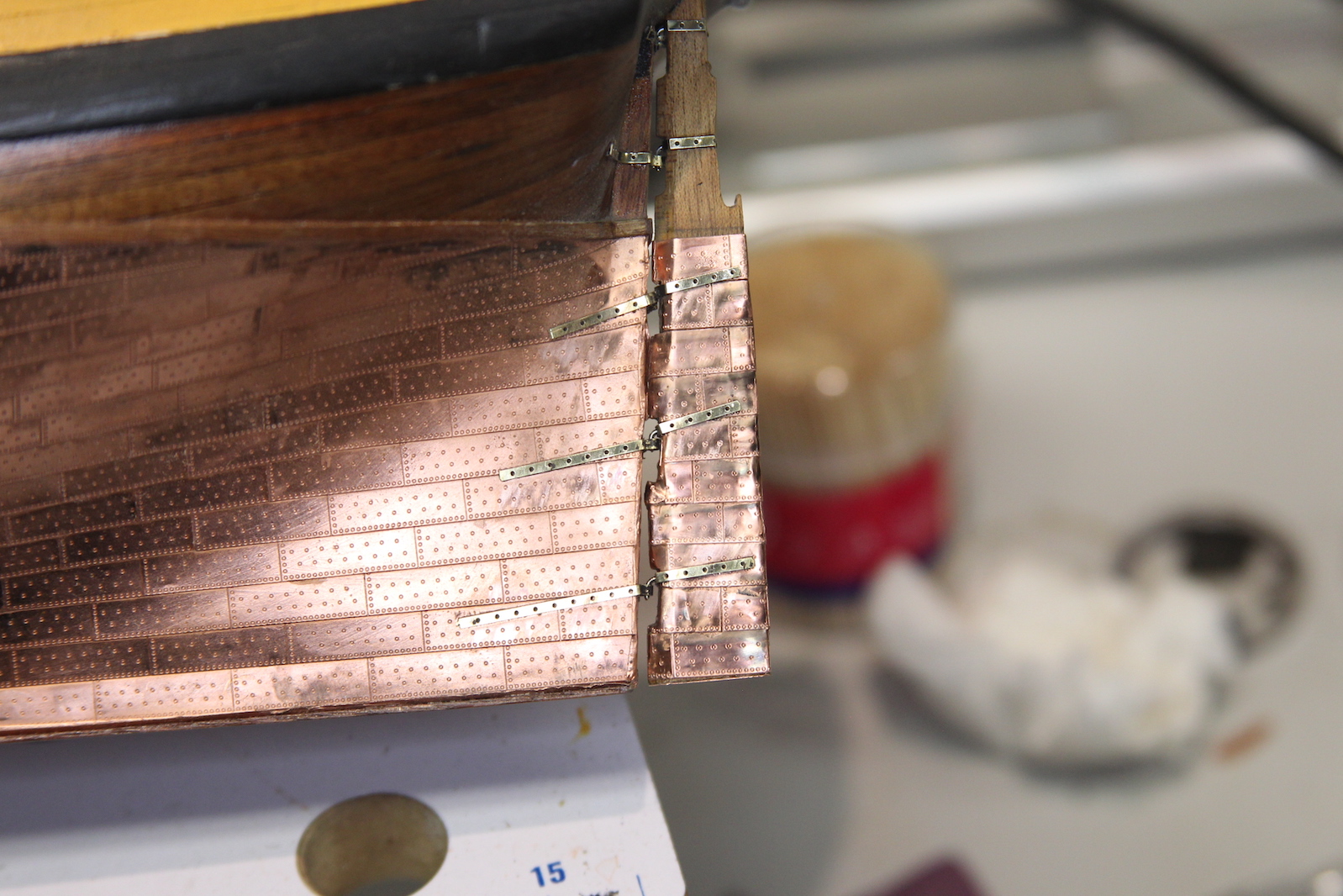
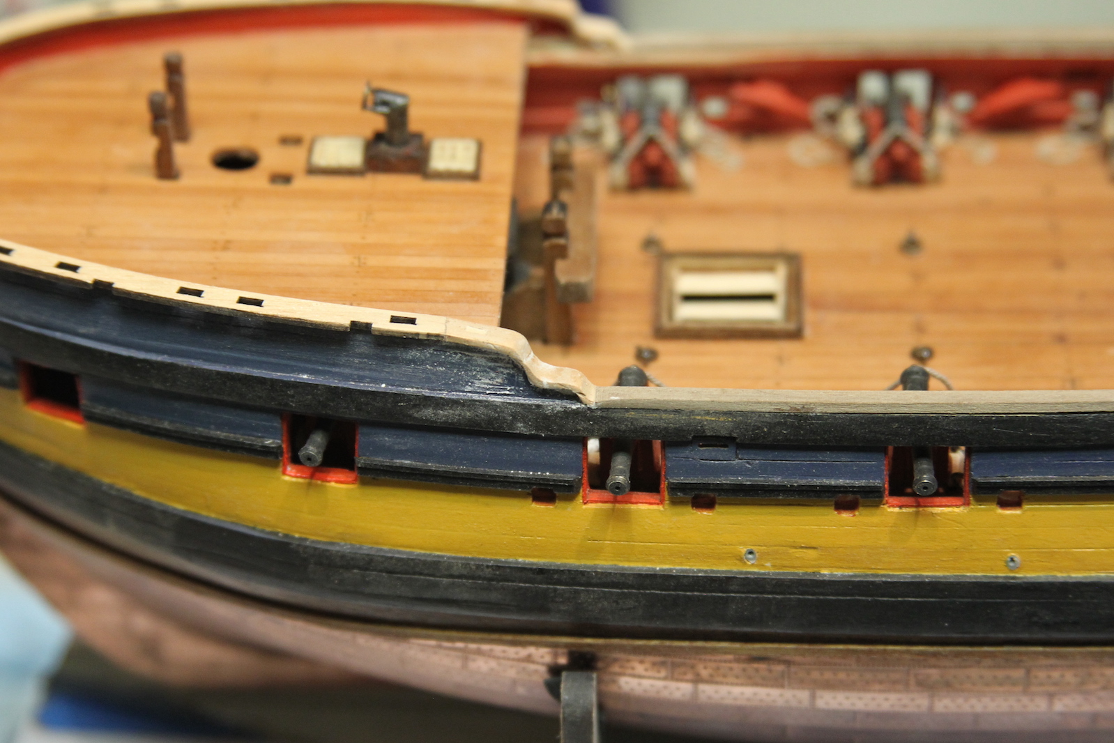
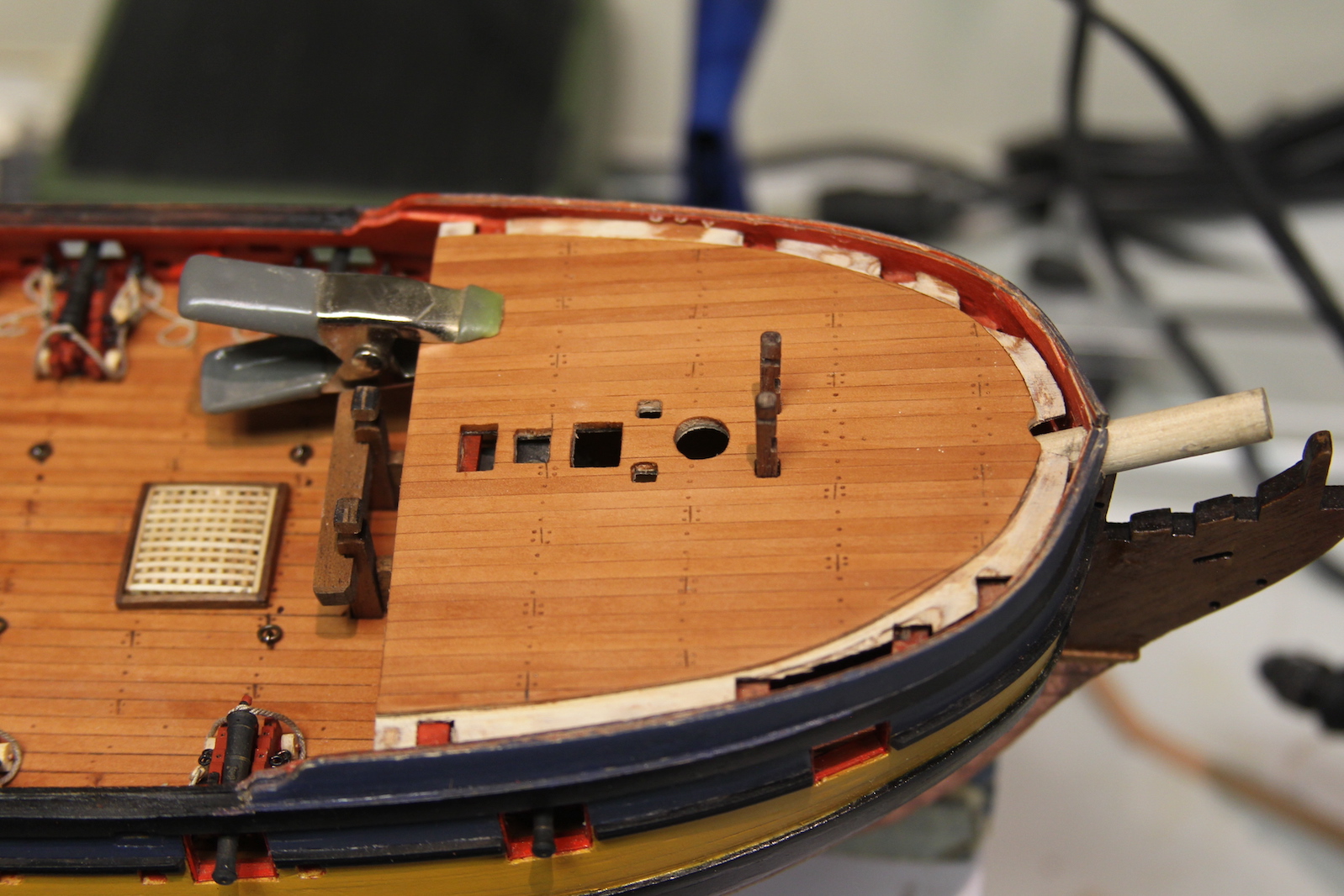
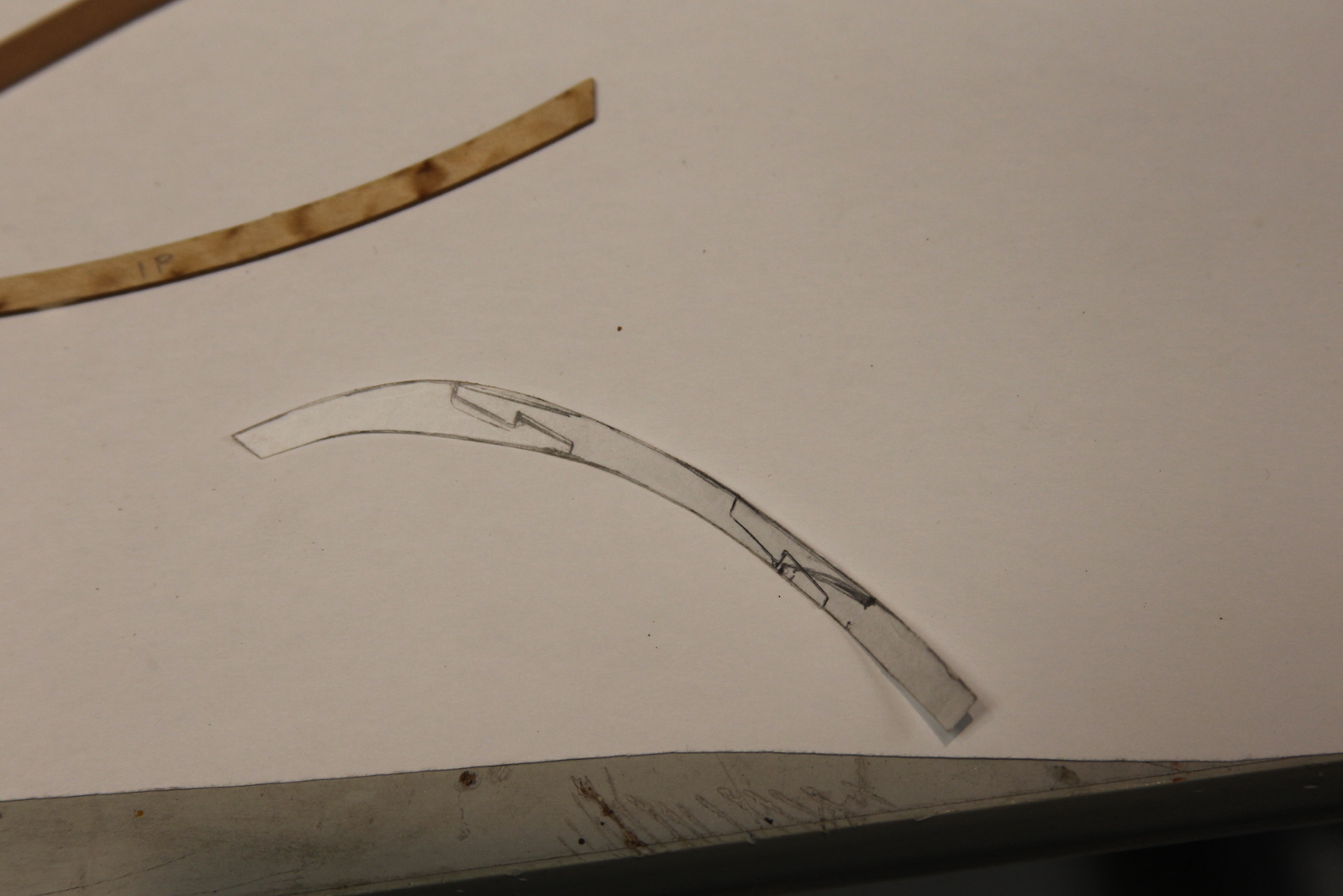
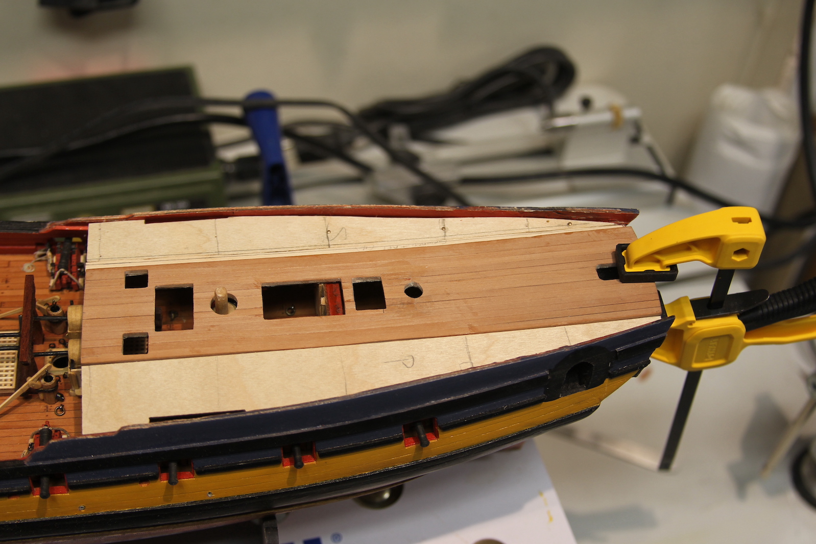
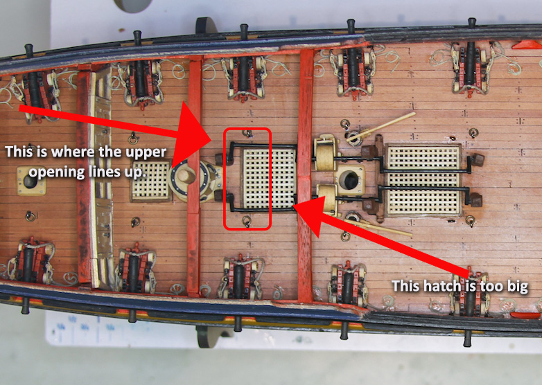
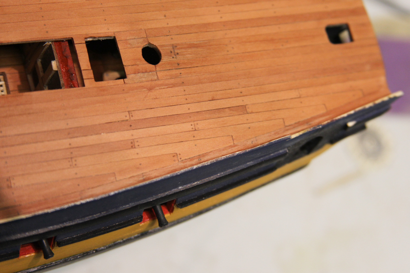
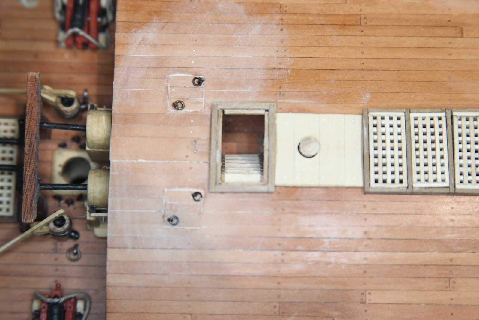
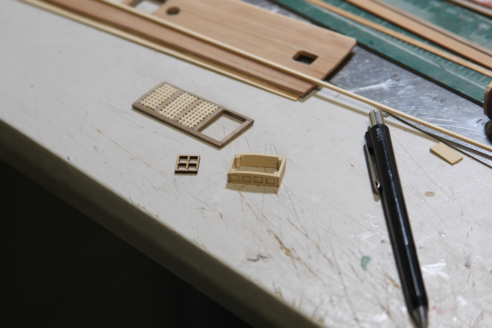
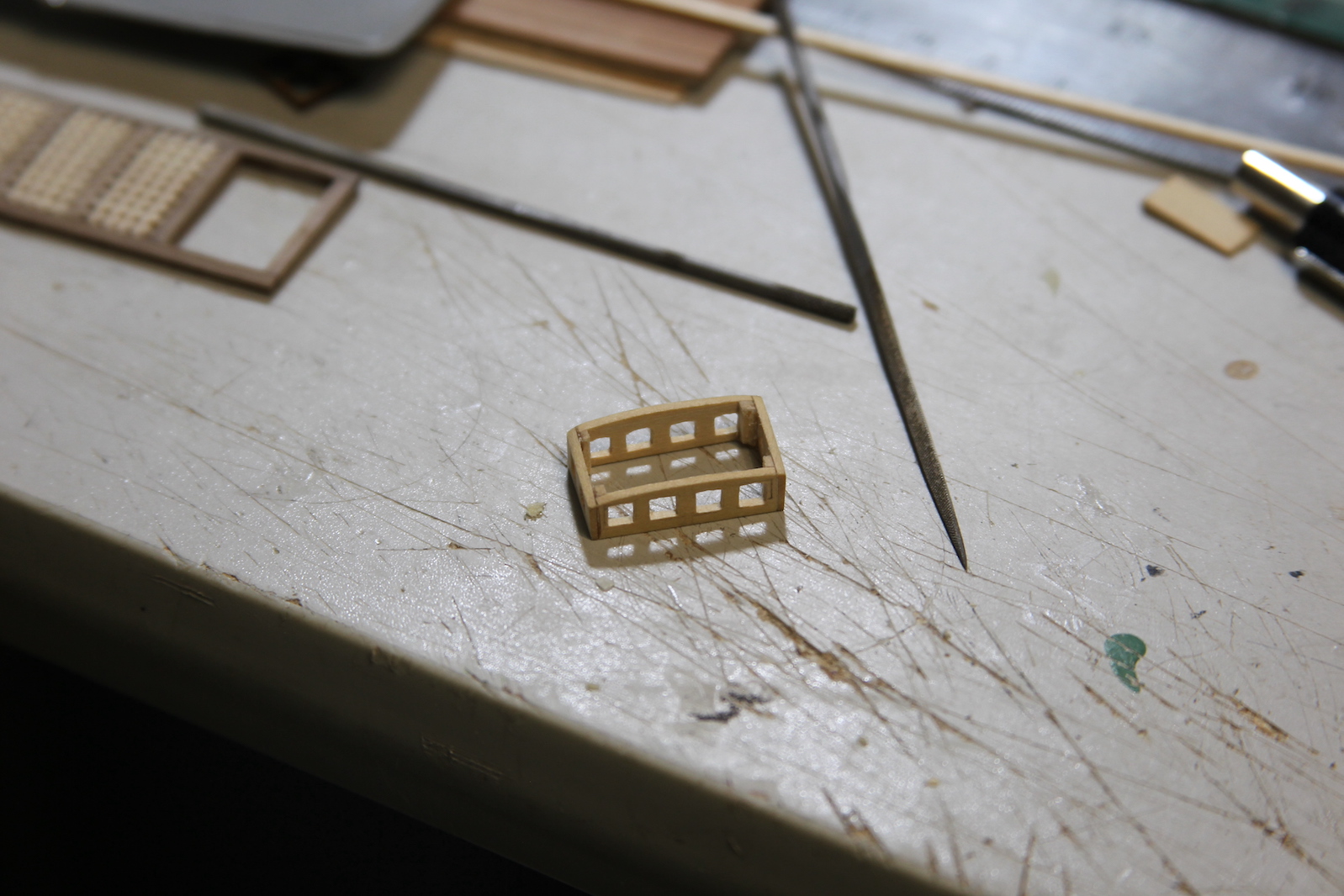
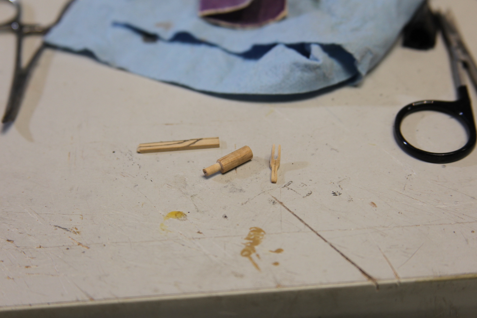
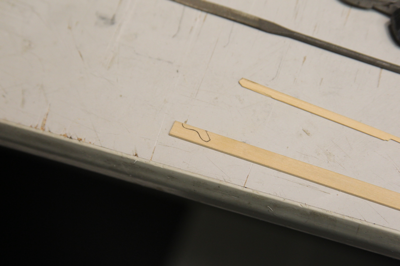
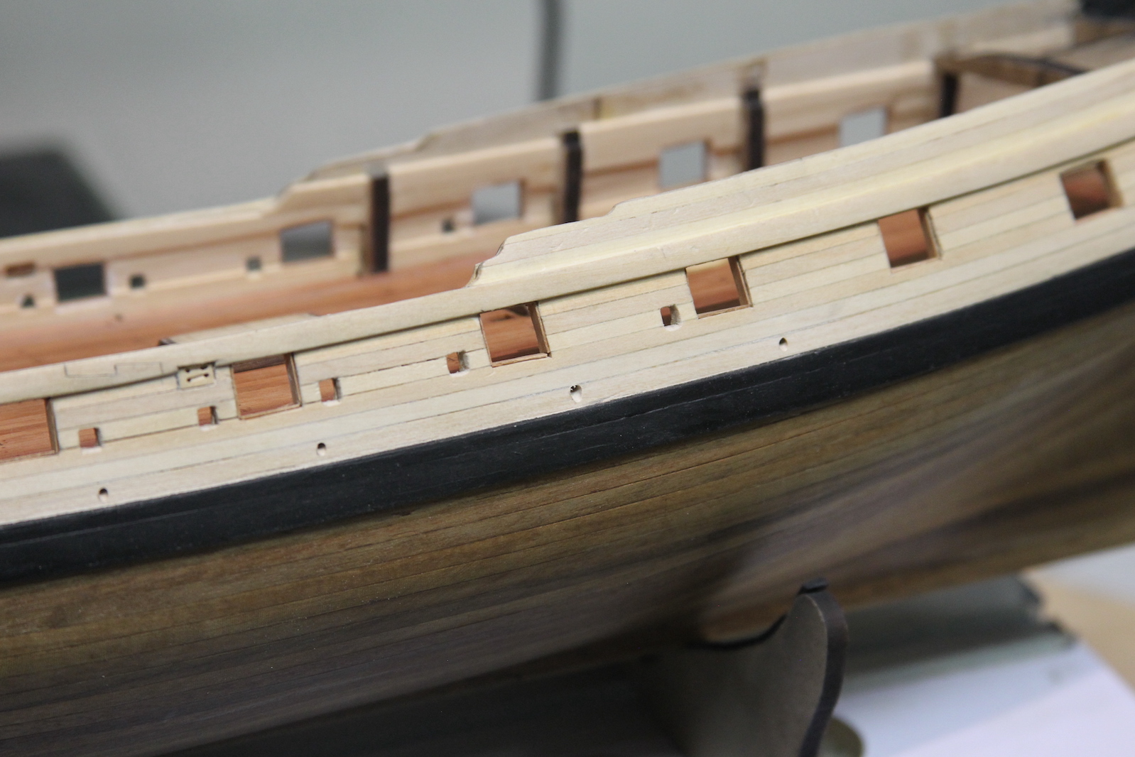
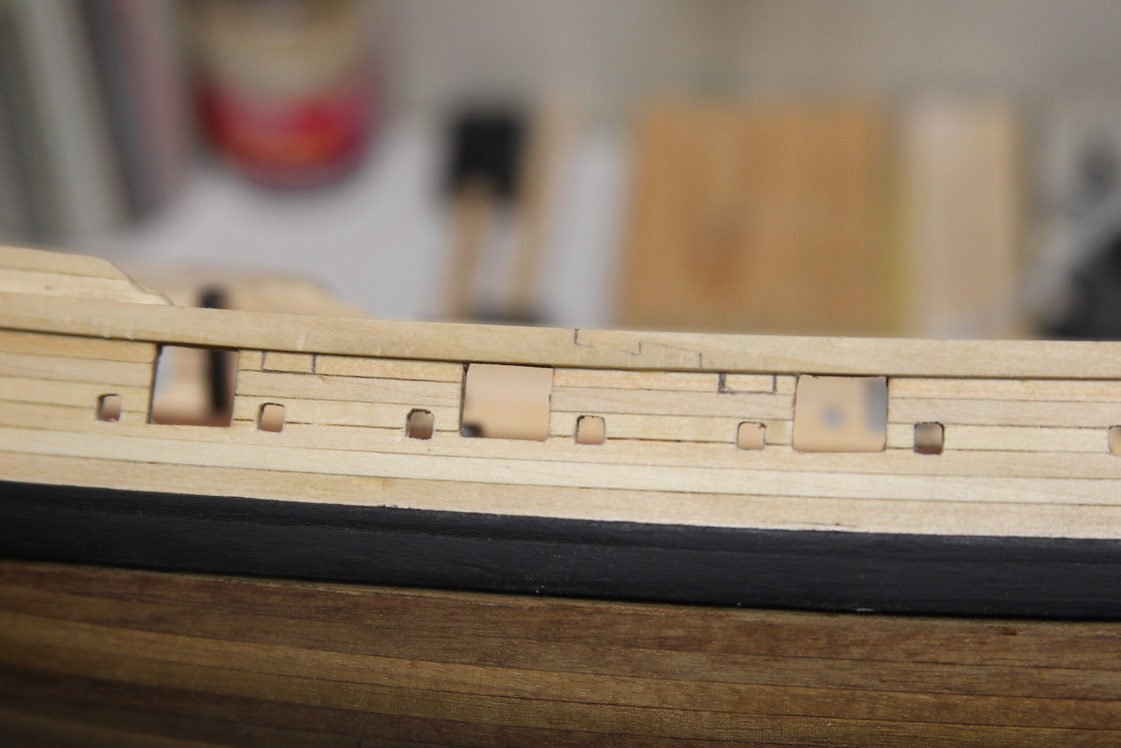
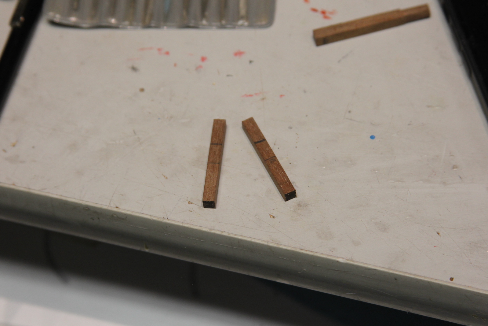
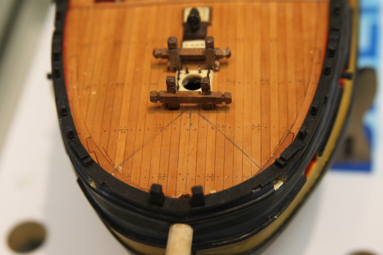
Catheads are the thick beams located on either side of the bow of the ship at about a 45 degree angle.  The beams contain sheaves (pulleys) that assist with raising and lowering the anchors. The anchors were enormously heavy, so the catbeam not only needed to be thick, but also often extended through the upper decks and was secured to (or part of) the framing below.     That was the case with the Pegasus, and I knew achieving this look would be a bit of a challenge. The catbeams supplied with the ship kit had a couple problems that couldn’t be overlooked – first they were too small. I can understand that from a manufacturing standpoint, as including them with the other laser cut parts just makes sense.  The second problem is that they don’t contain any sheaves (or even simulated sheaves) at the end – this just makes them unrealistic.      First, I measured out the angles I’d need off the bow and identified where I’d need to cut through the bulwarks as well as carve out the deck.  Once again in the ‘failed to look far enough ahead’ category, this happens to line up right where my scarph joints on the margin plank are.  Oh well – hopefully that won’t be super noticeable to most folks.  For the catheads themselves, I started with a couple of 5 x 5mm pieces of walnut, measured them out and a shaped them. I’m not so ambitious as to have created all the sheaves out of metal (I prefer simulating most of them with just drilled holes and carved lives between). But I felt it was necessary with the cathead sheaves as they are very visible, but also will need to be functional later when I rig the anchors.  

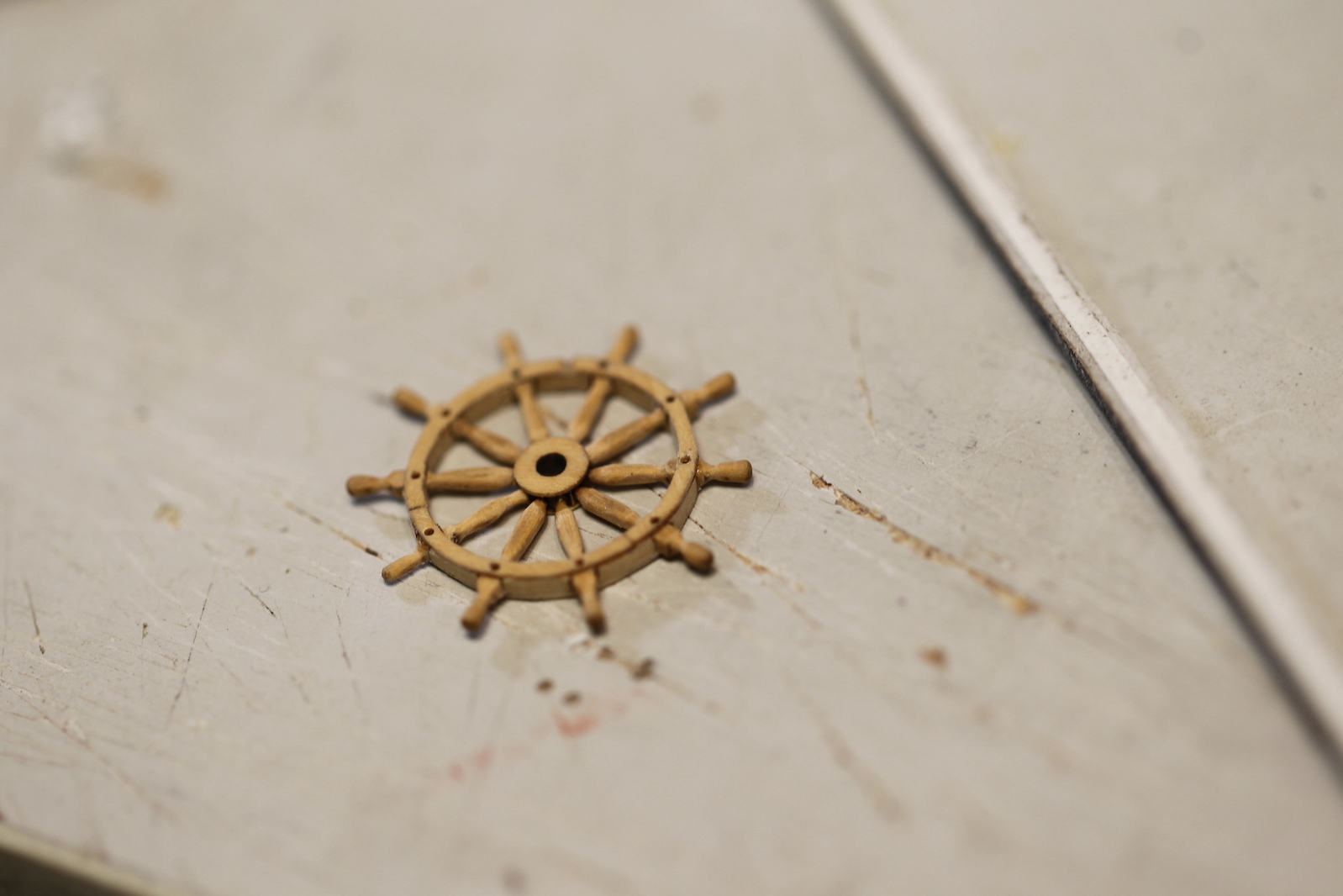
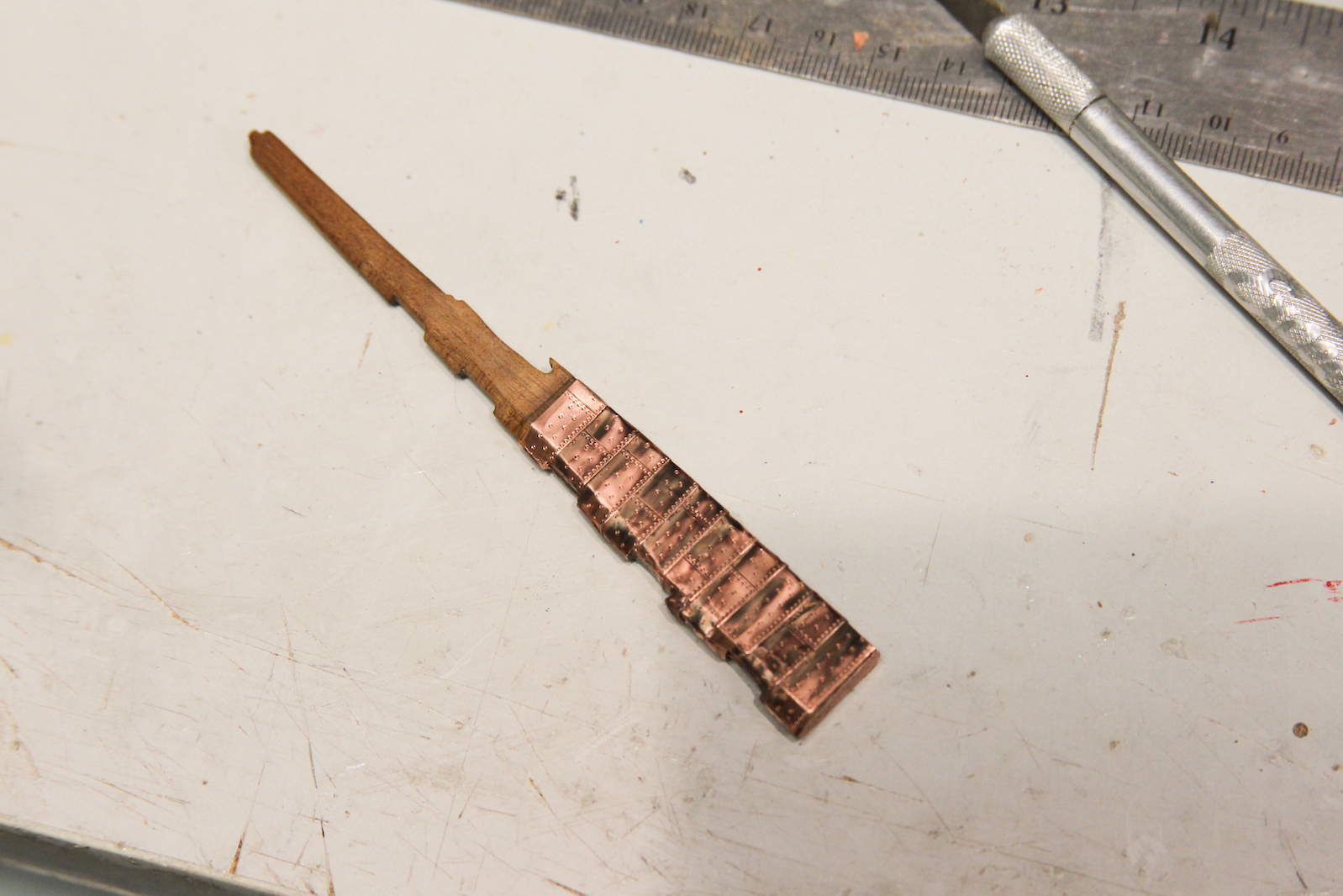
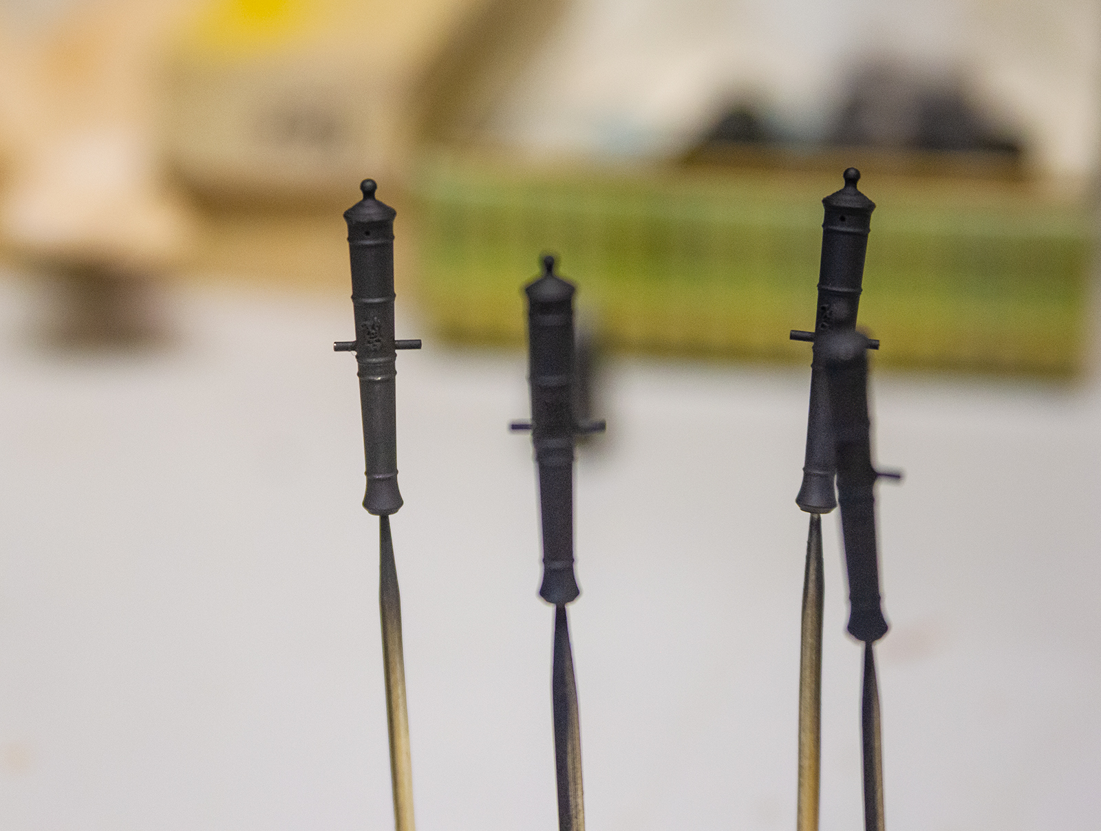
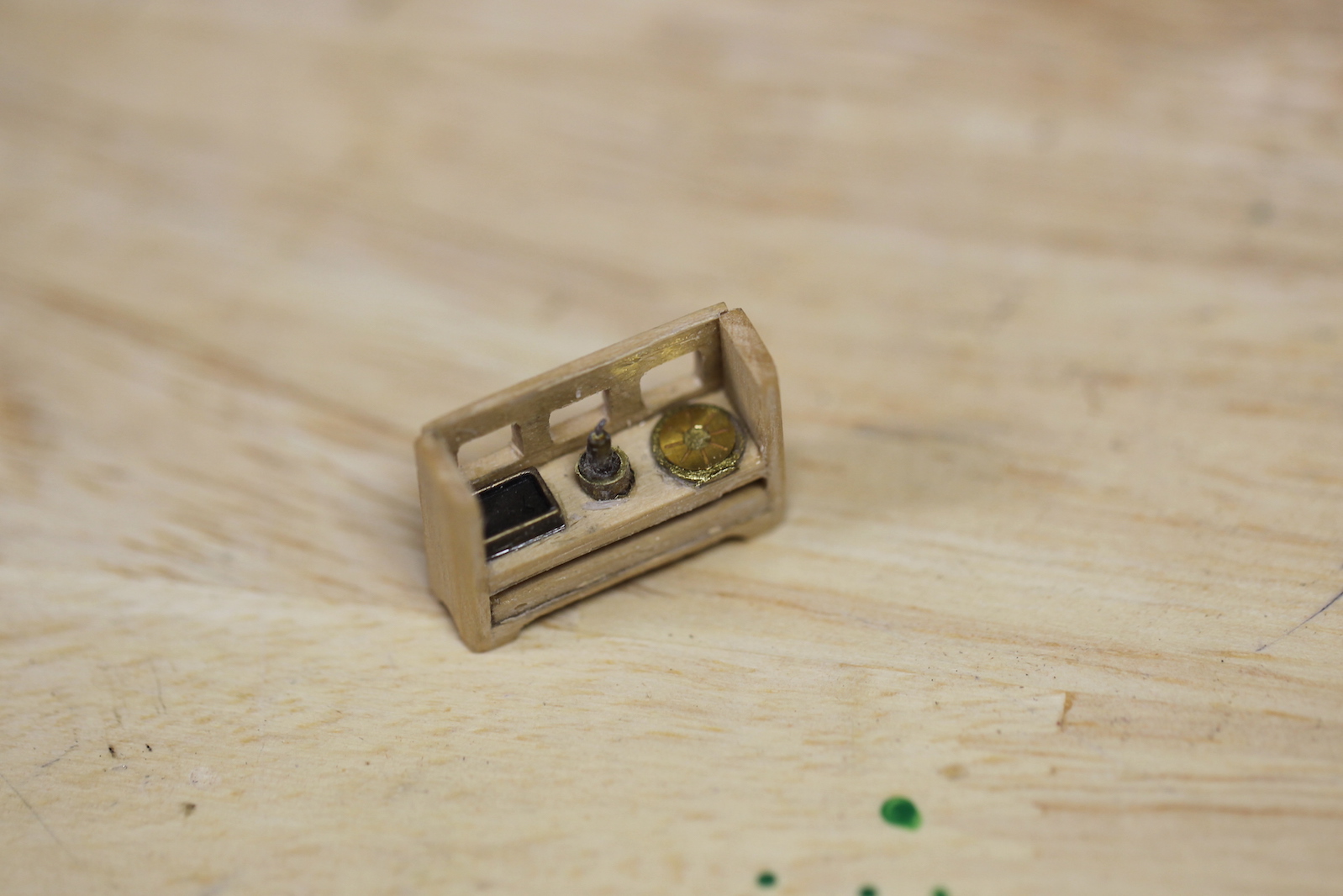
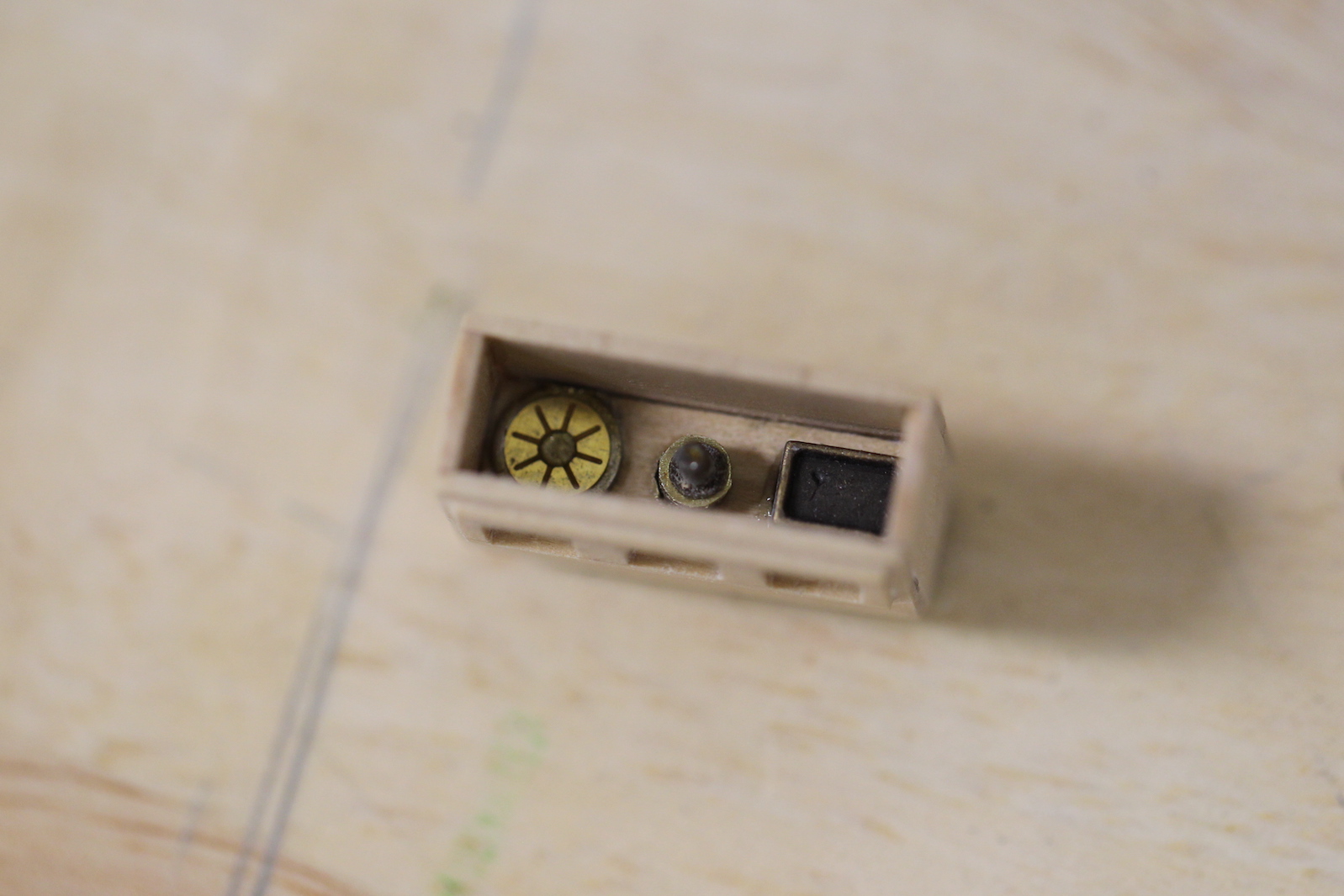
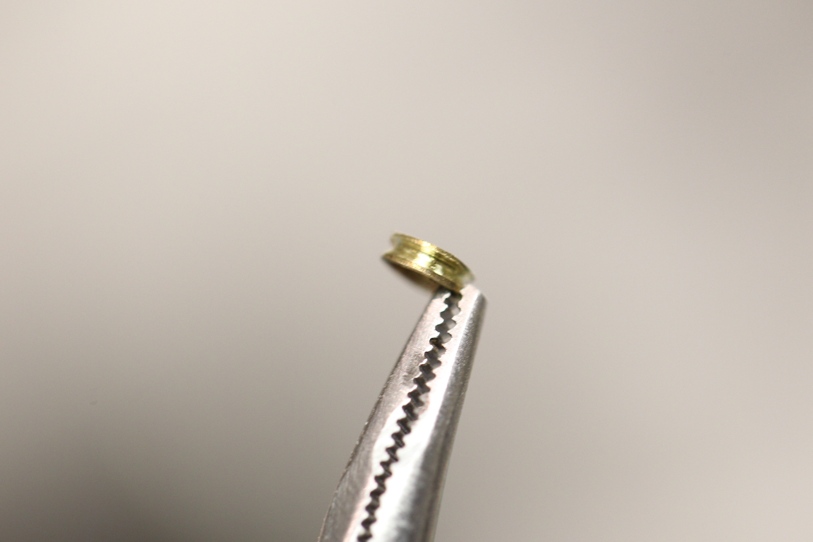
  I’m not a big fan of creating functional sheaves for most things – as they are very difficult to do properly and are essentially unusable. Instead, I typically create a simulated sheave by drilling a couple holes and carving a line between them which can’t be seen once rigged. However, these sheaves are very noticeable, so I took the extra effort to make metal ones.    

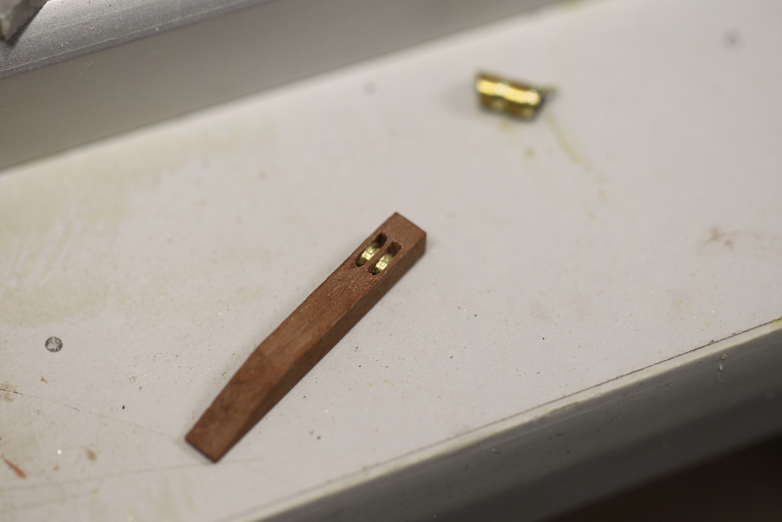
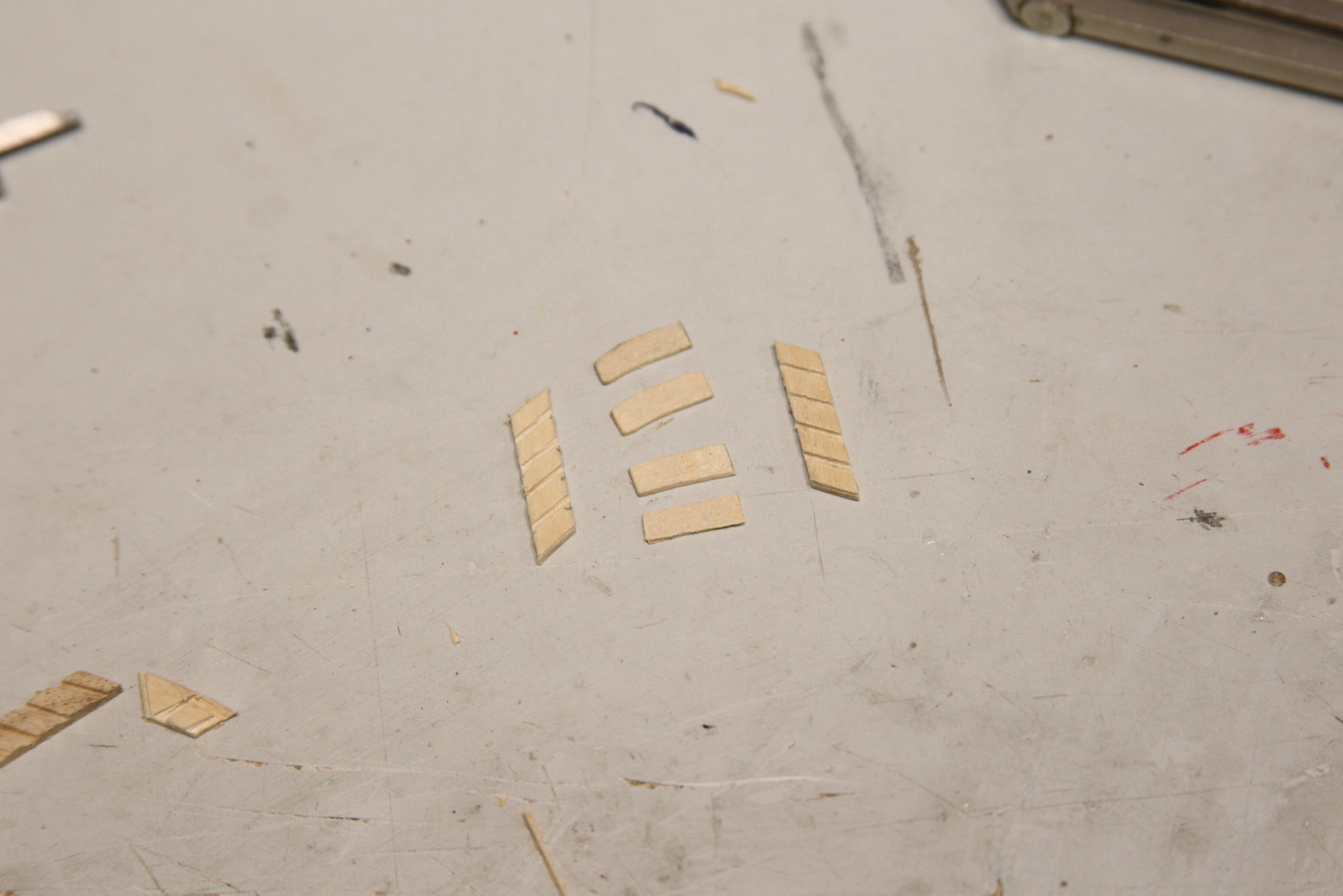
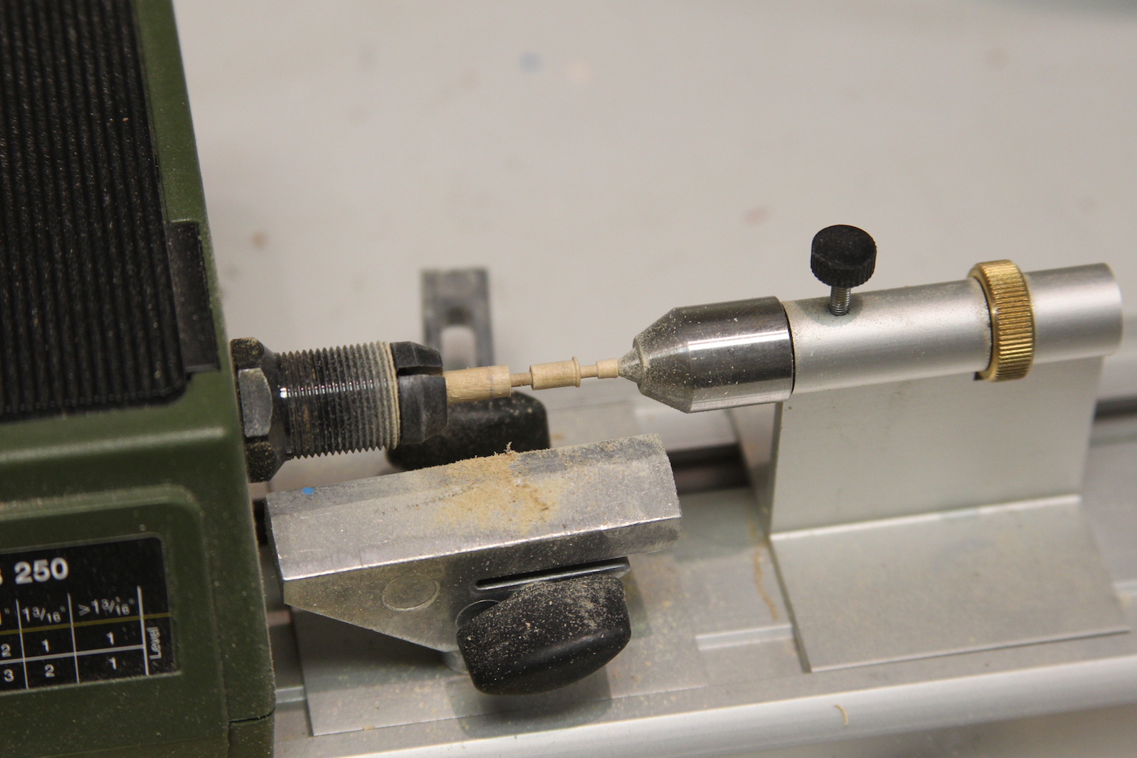
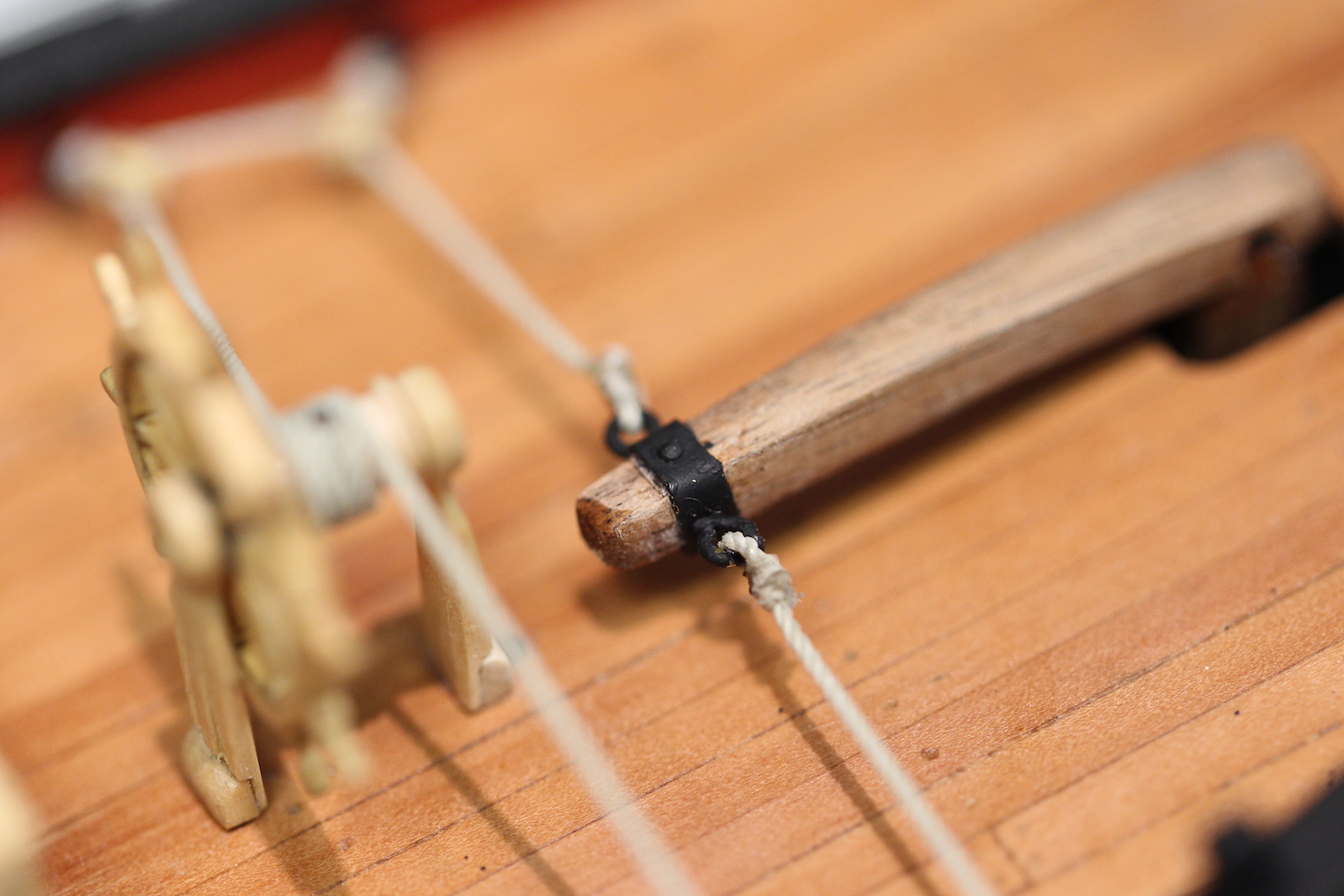
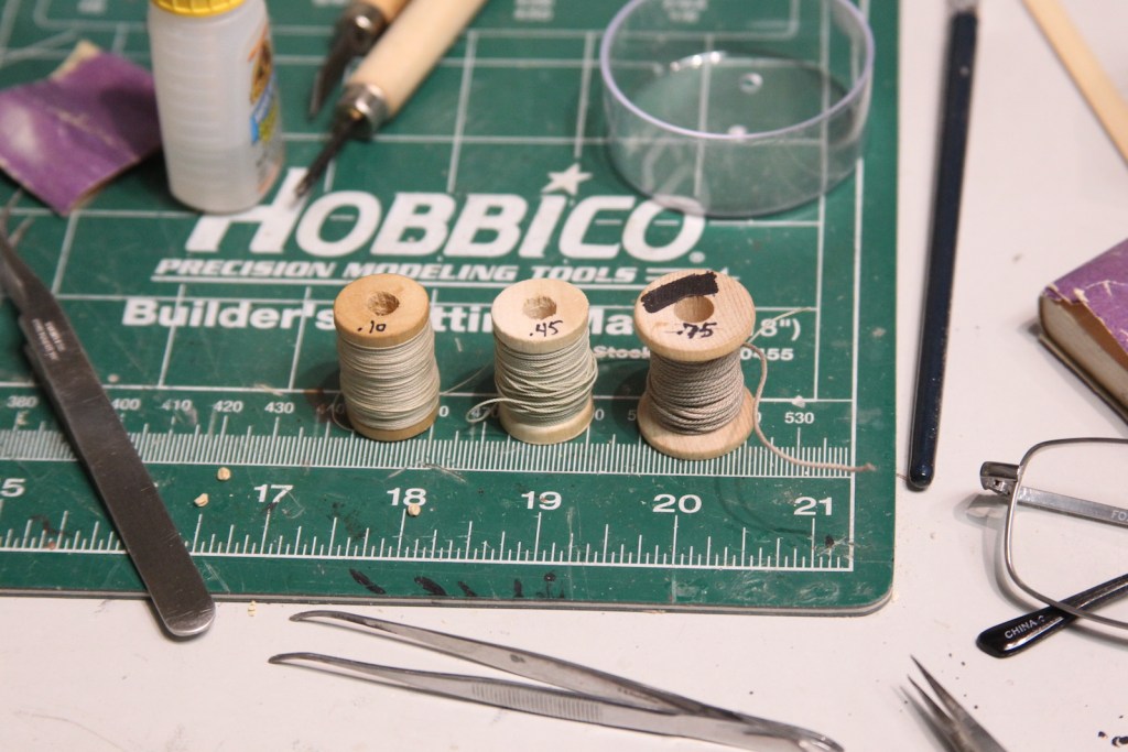
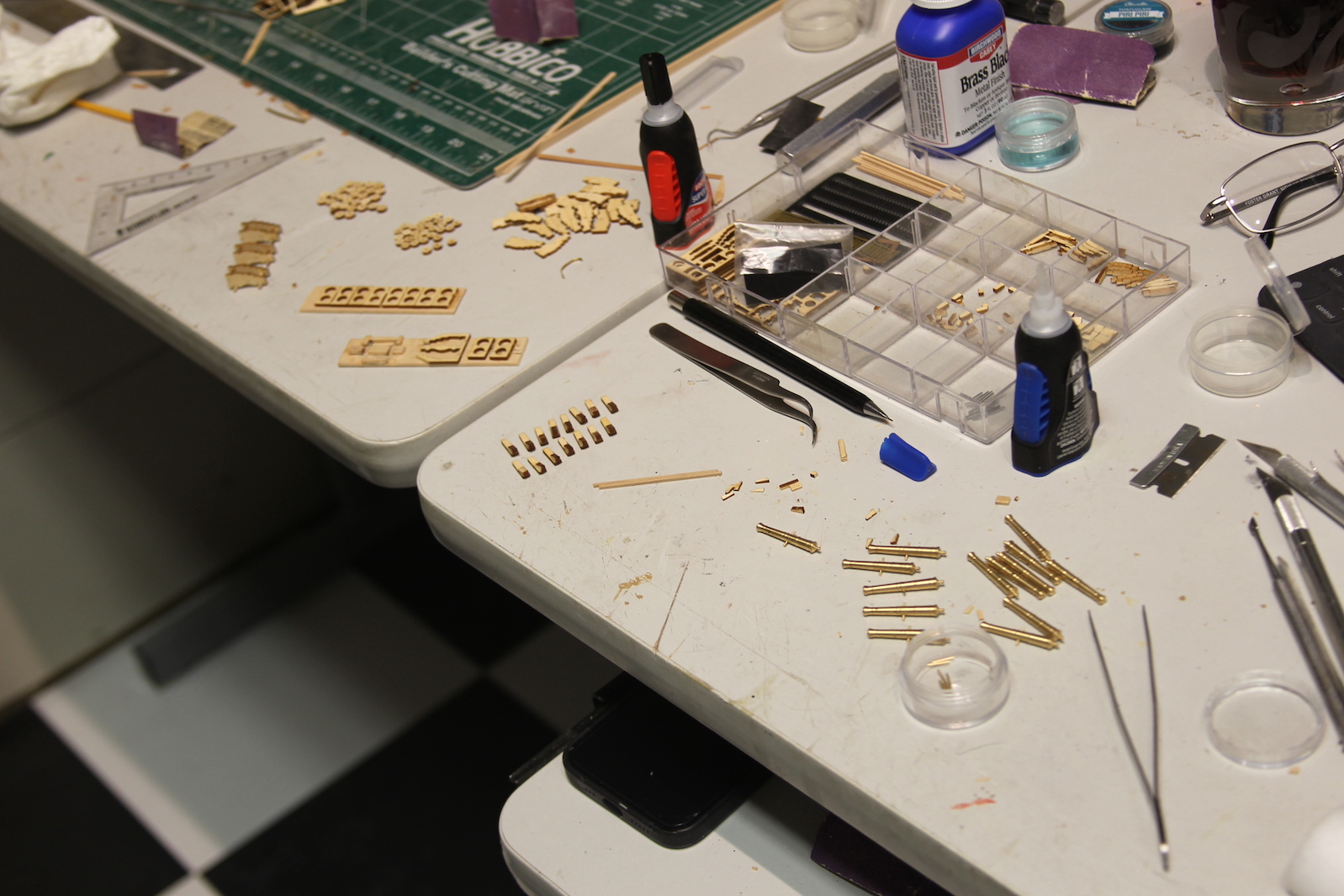
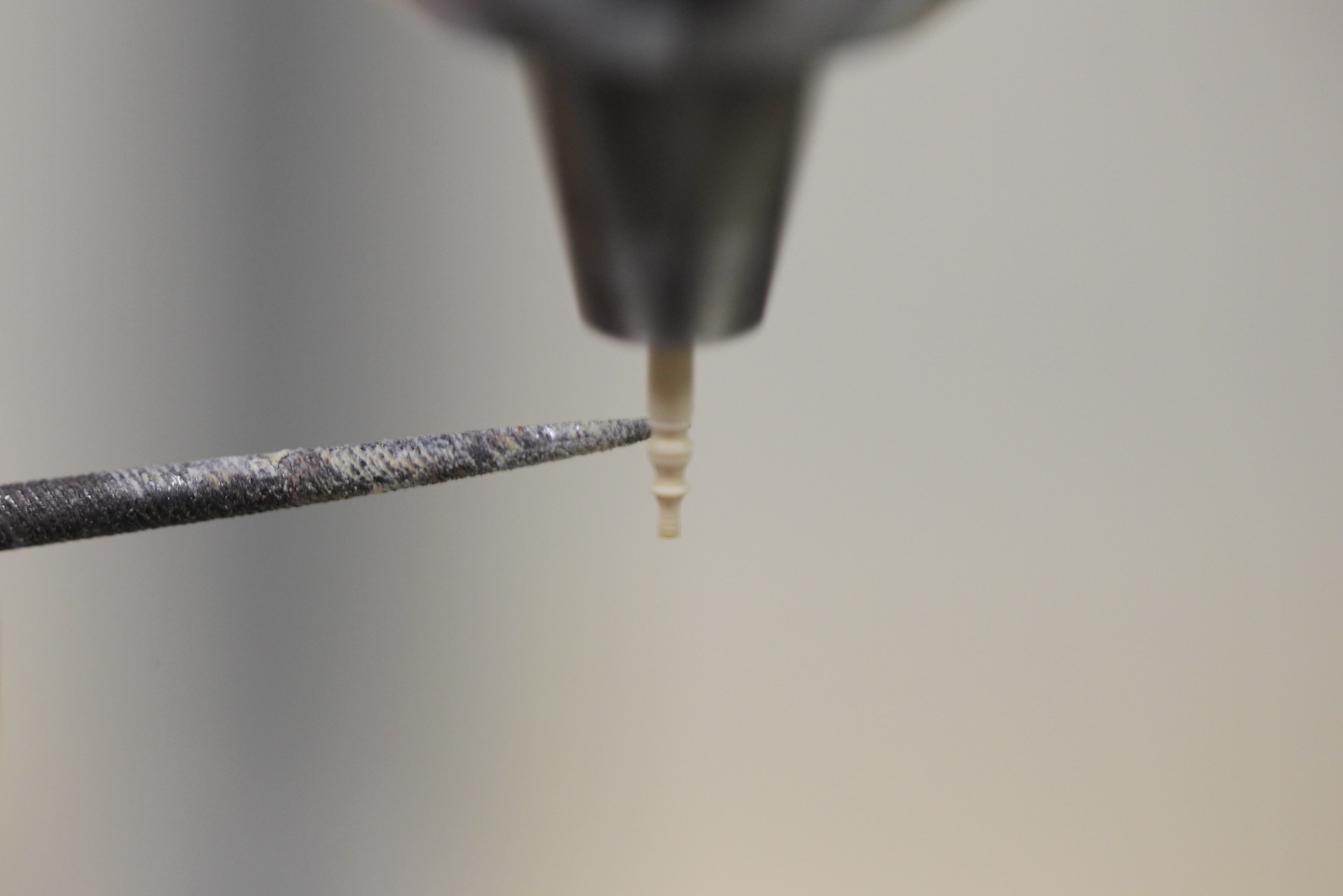
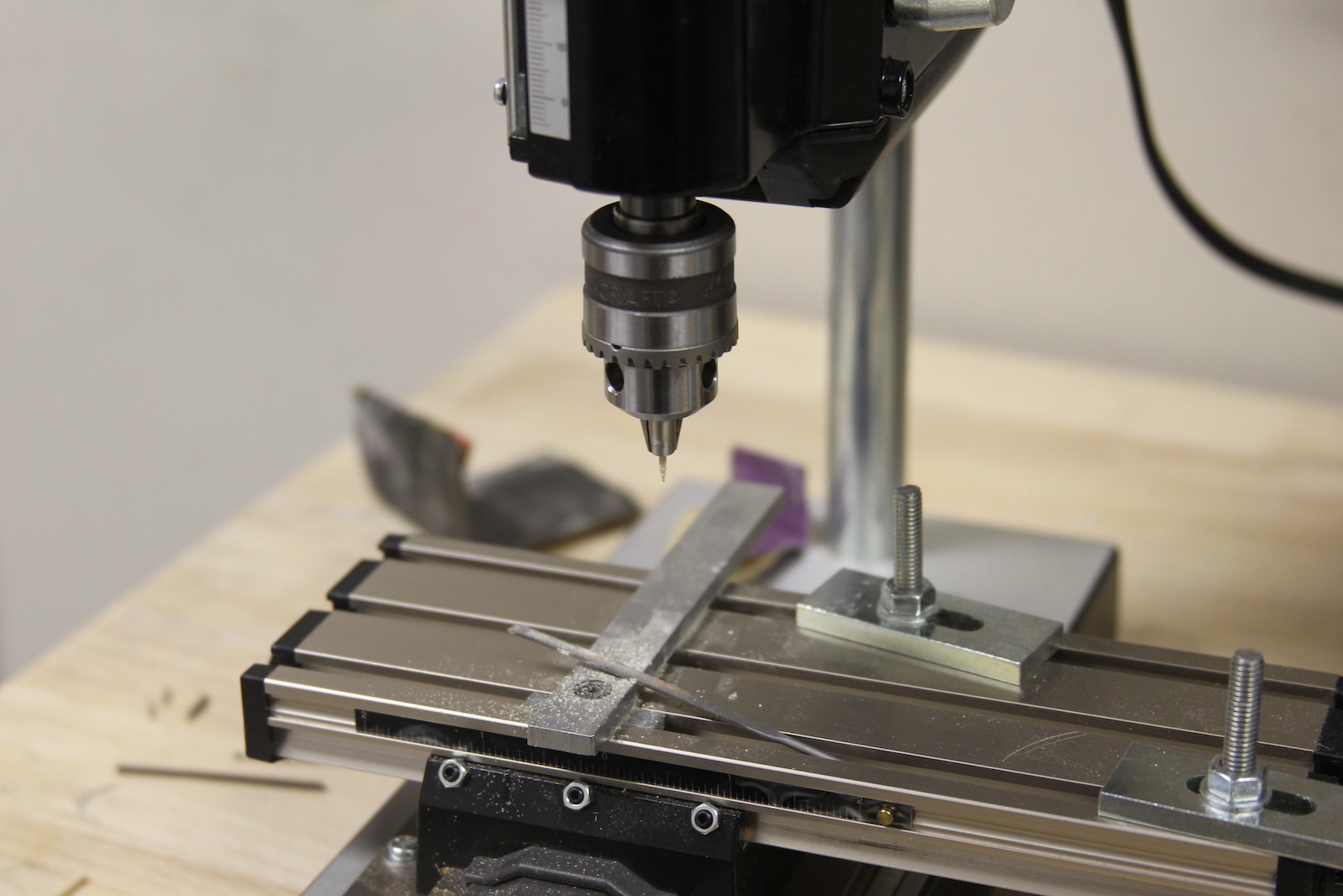
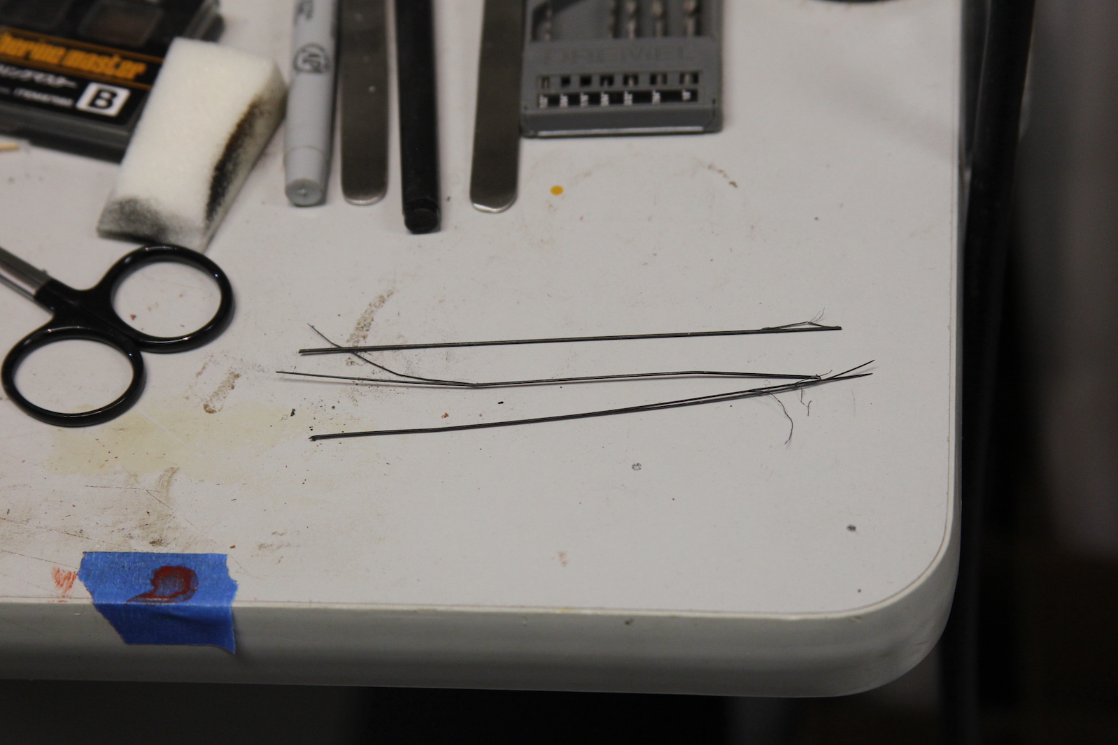
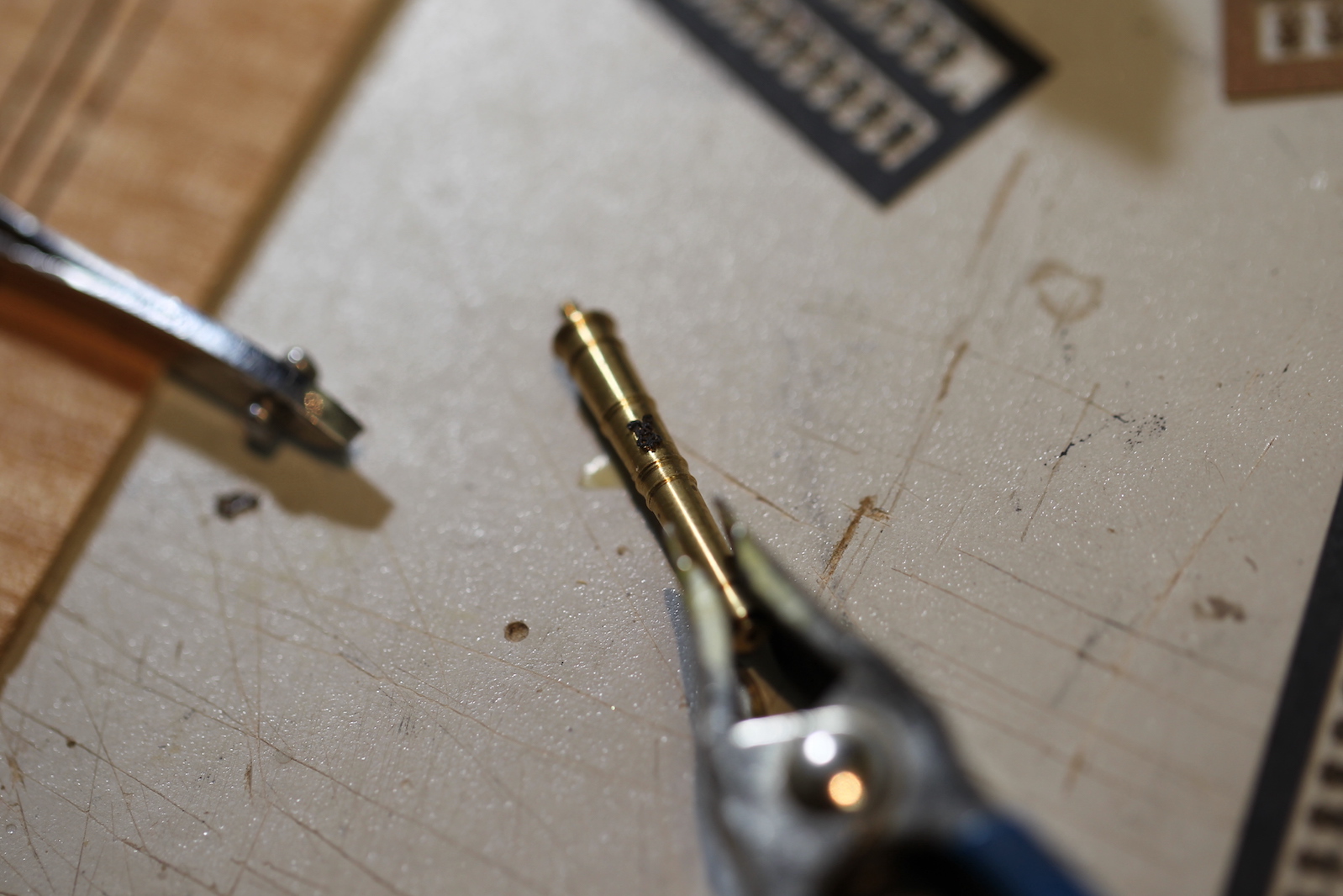
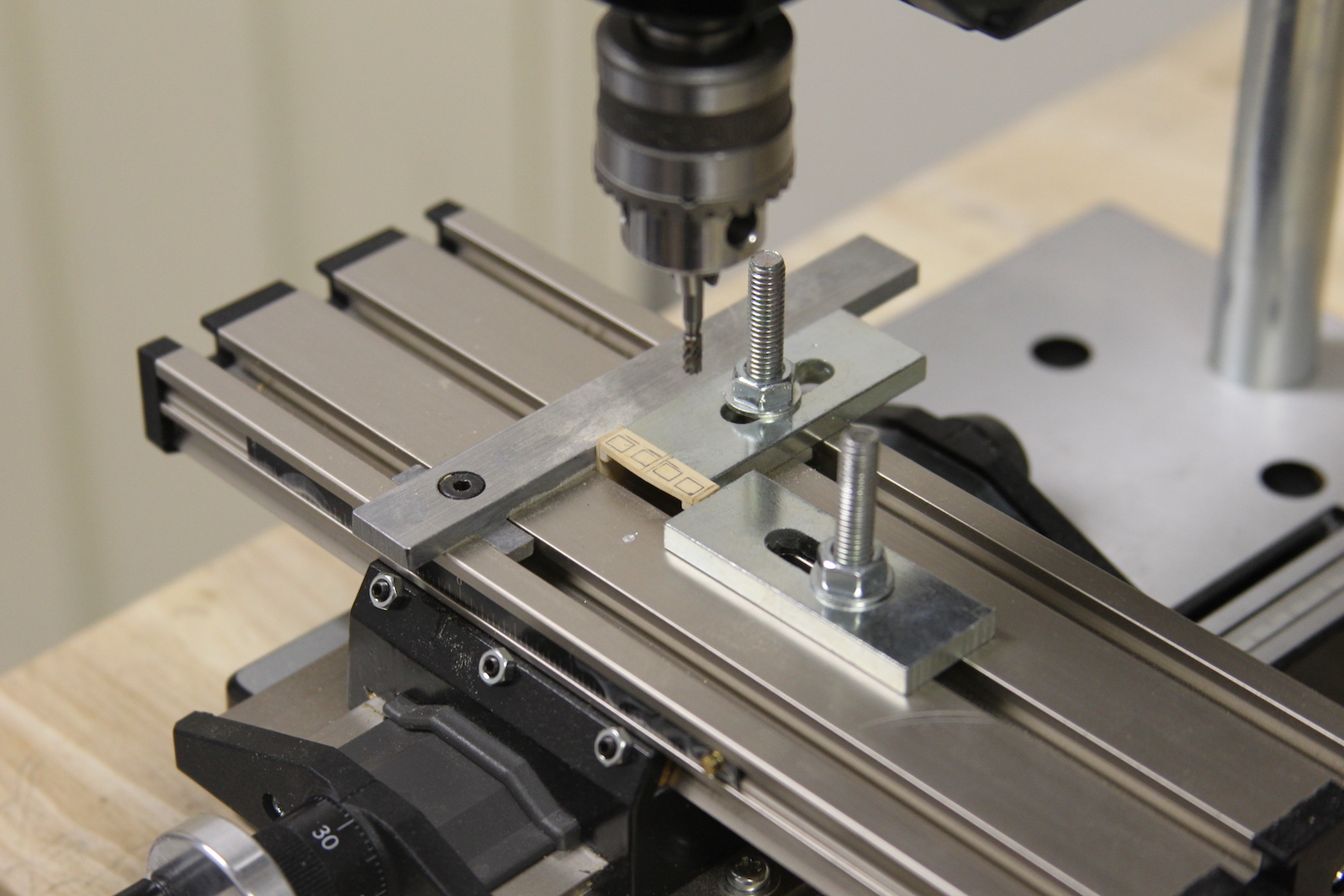
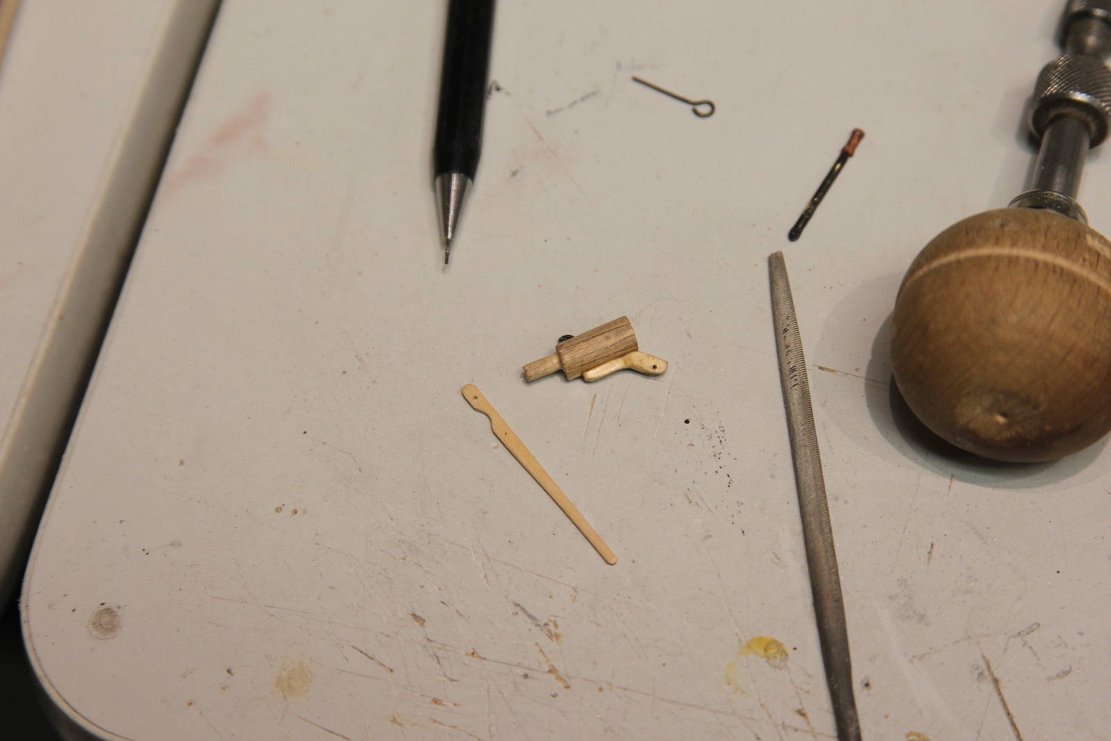
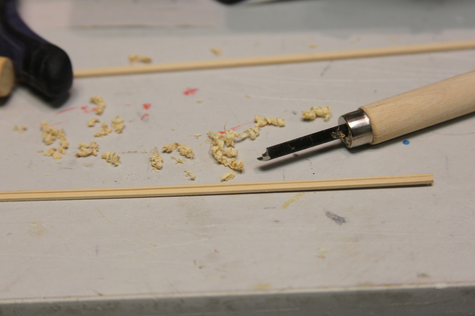
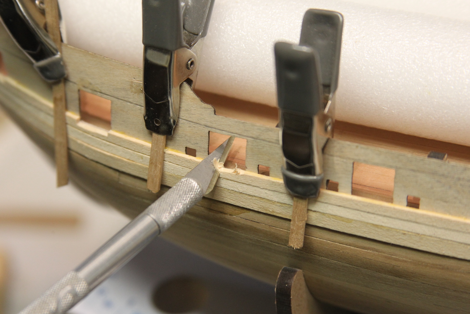
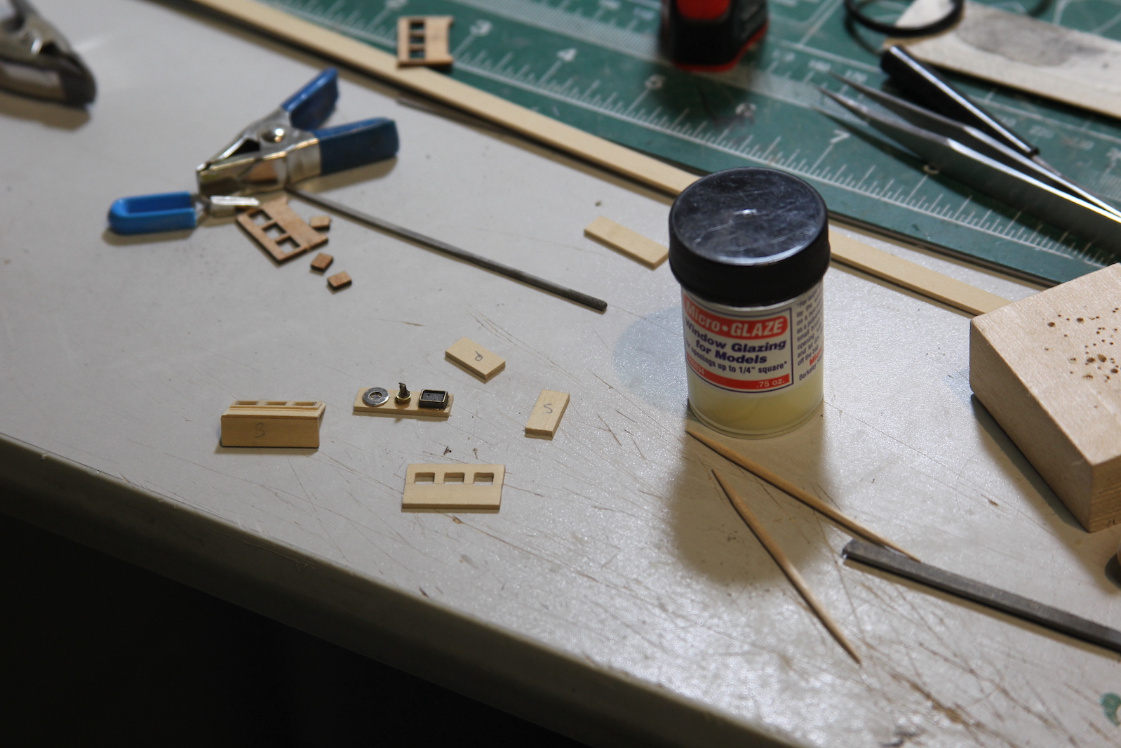
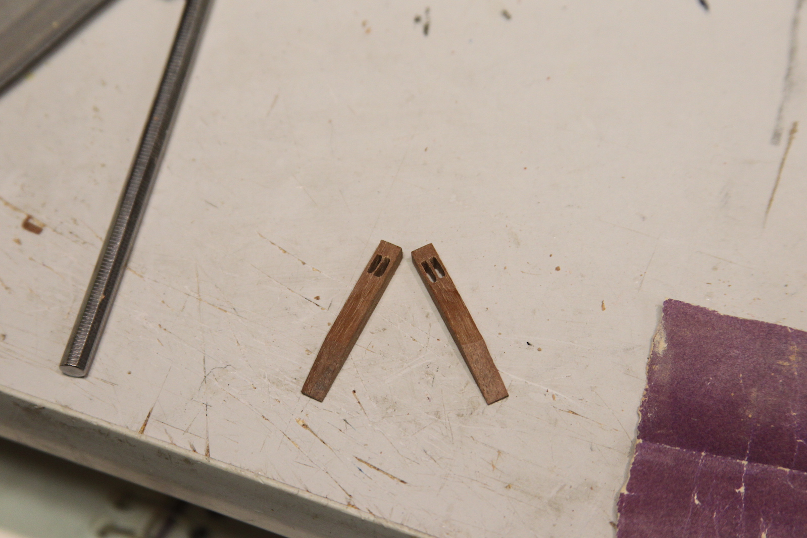
 First I drilled out a series of holes for the sheaves, then used this handy sanding string to size them out. The the metal sheaves I actually chose a brass  tube – a little different choice, as most folks create sheaves from a brass rod.  I carved out the groove on the lathe.  I chose the tube because it’s SUPER difficult for me to get a nice hole drilled through the brass. I just can’t seem to get a strong enough drill bit that holds up without bending or snapping off.  The cutting the sheave from a tube means I only had to drill through the wood to place the bolt/pin.    

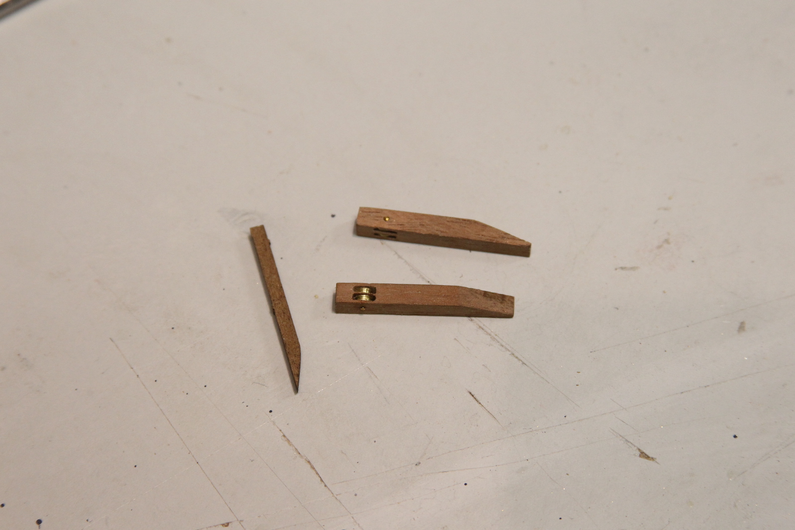
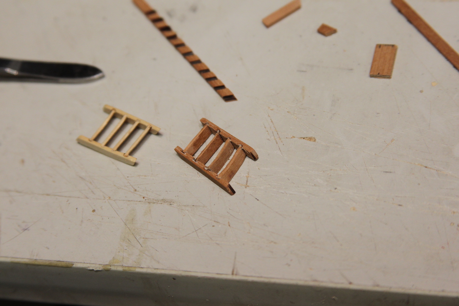
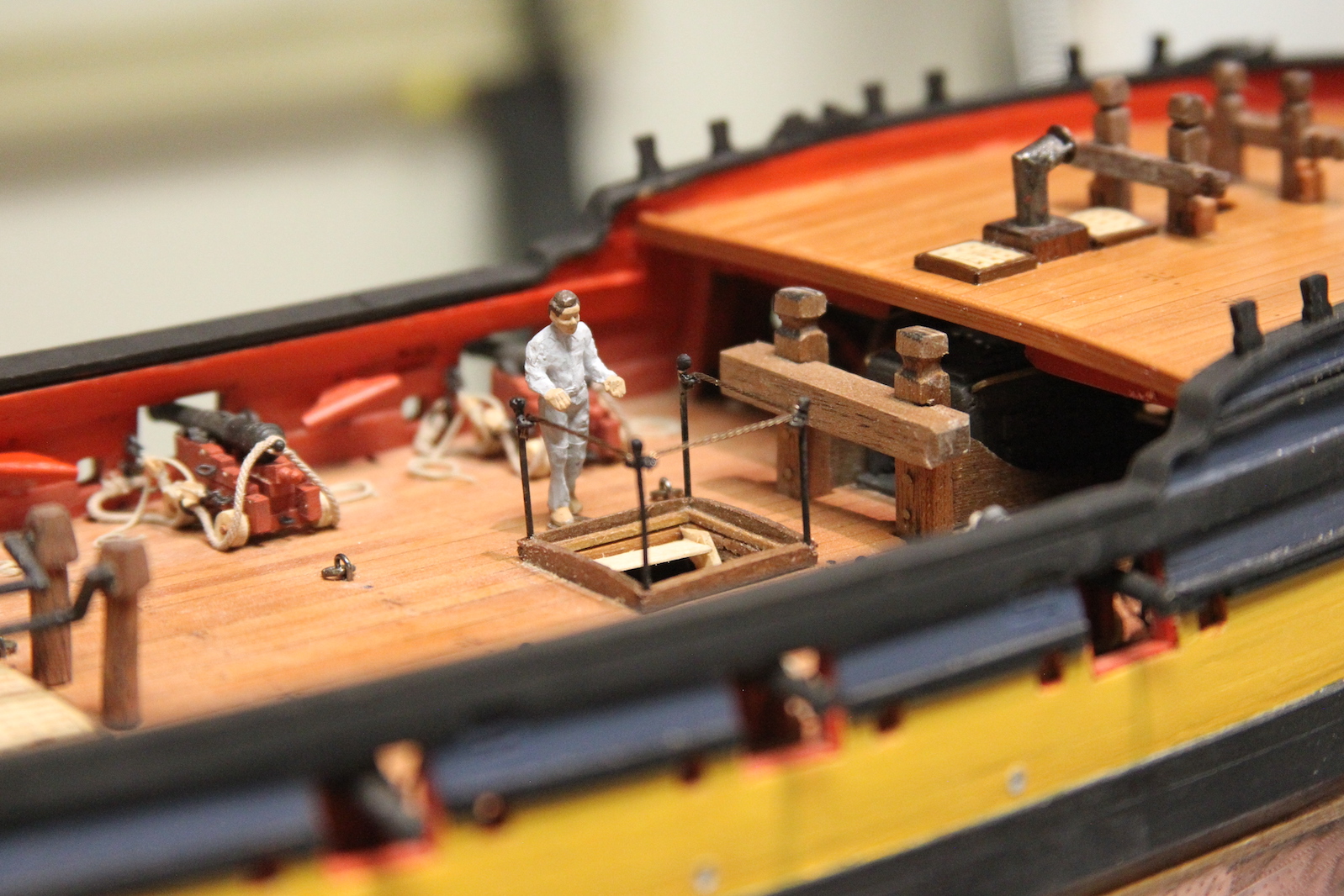
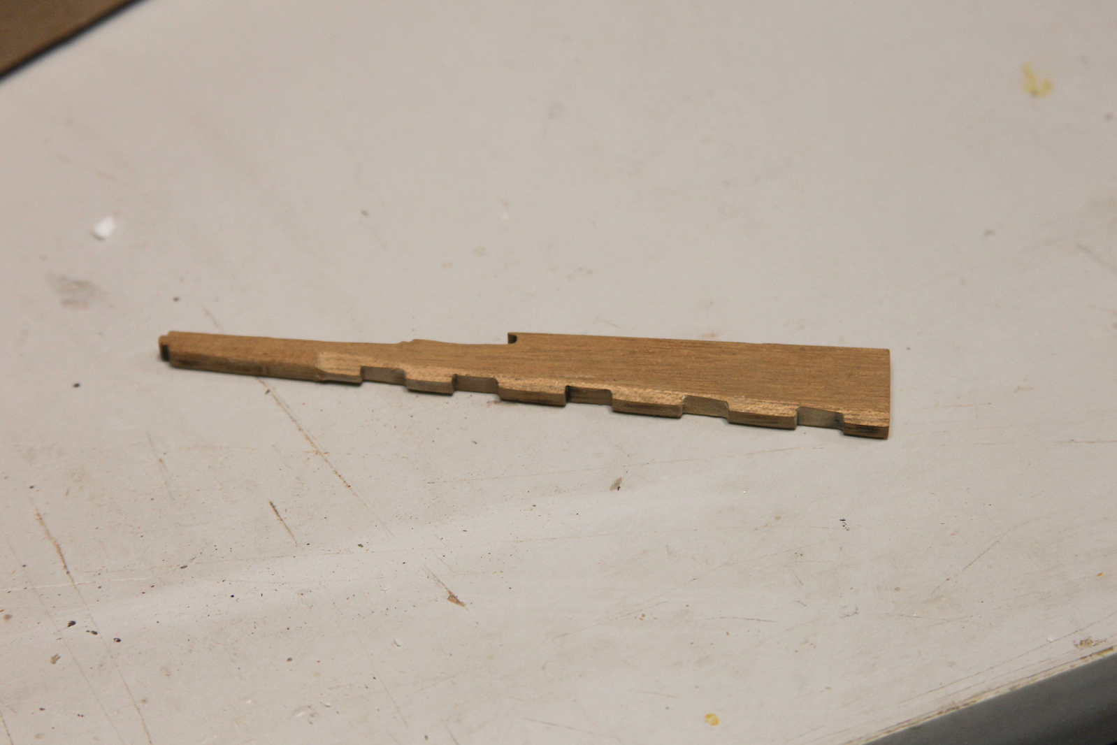
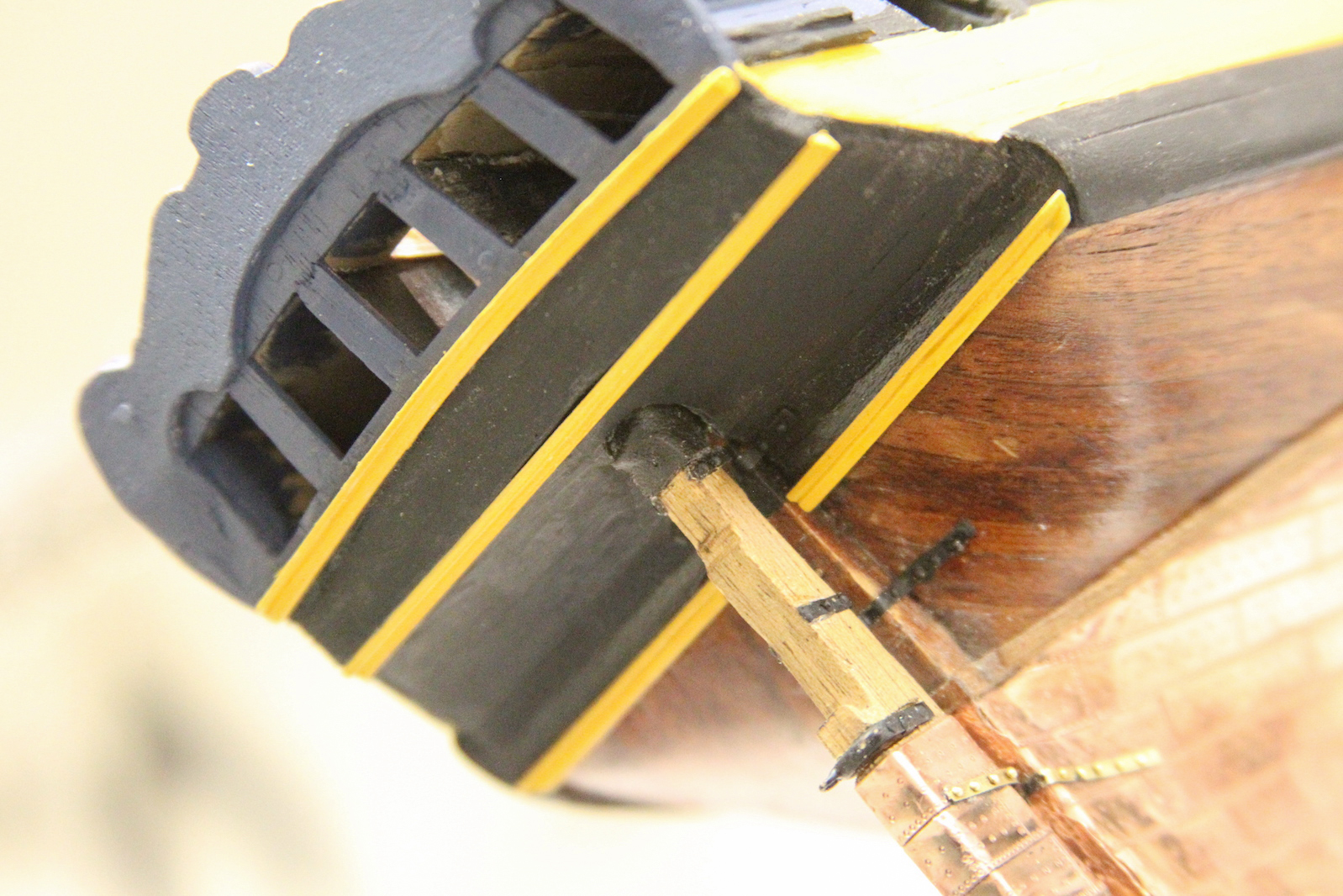
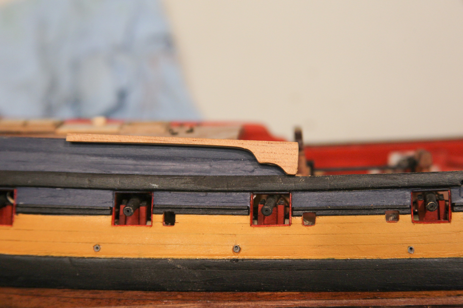
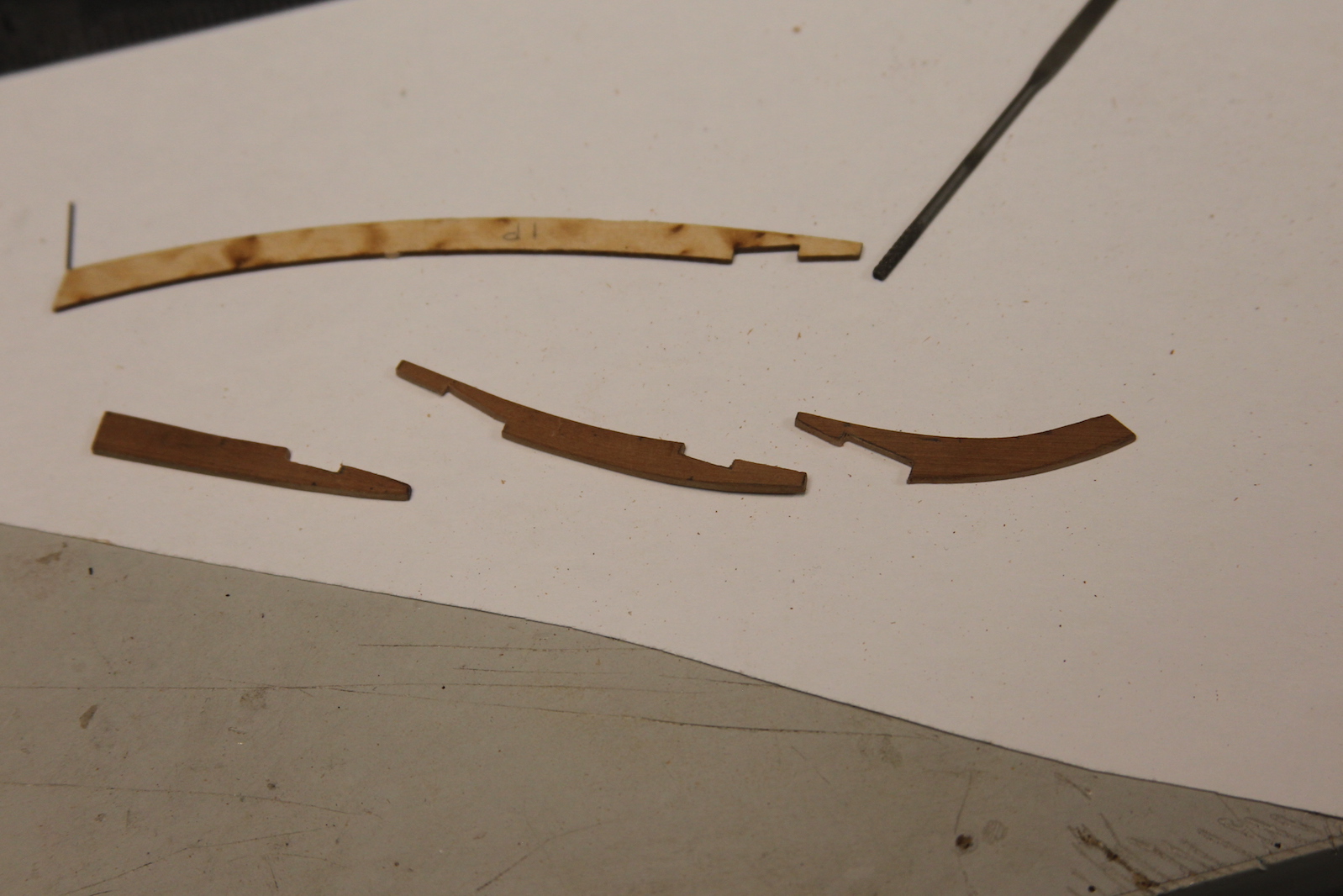
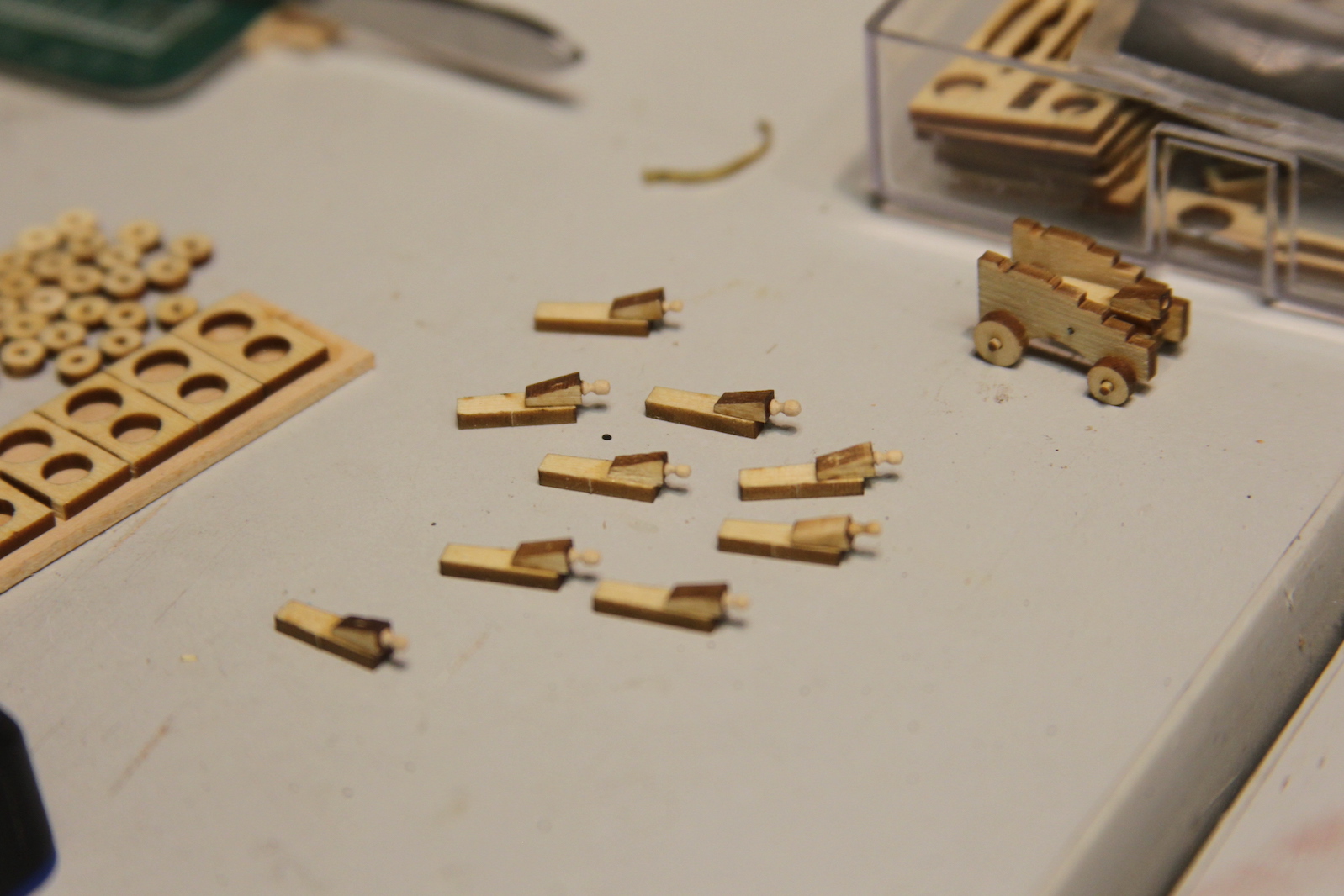
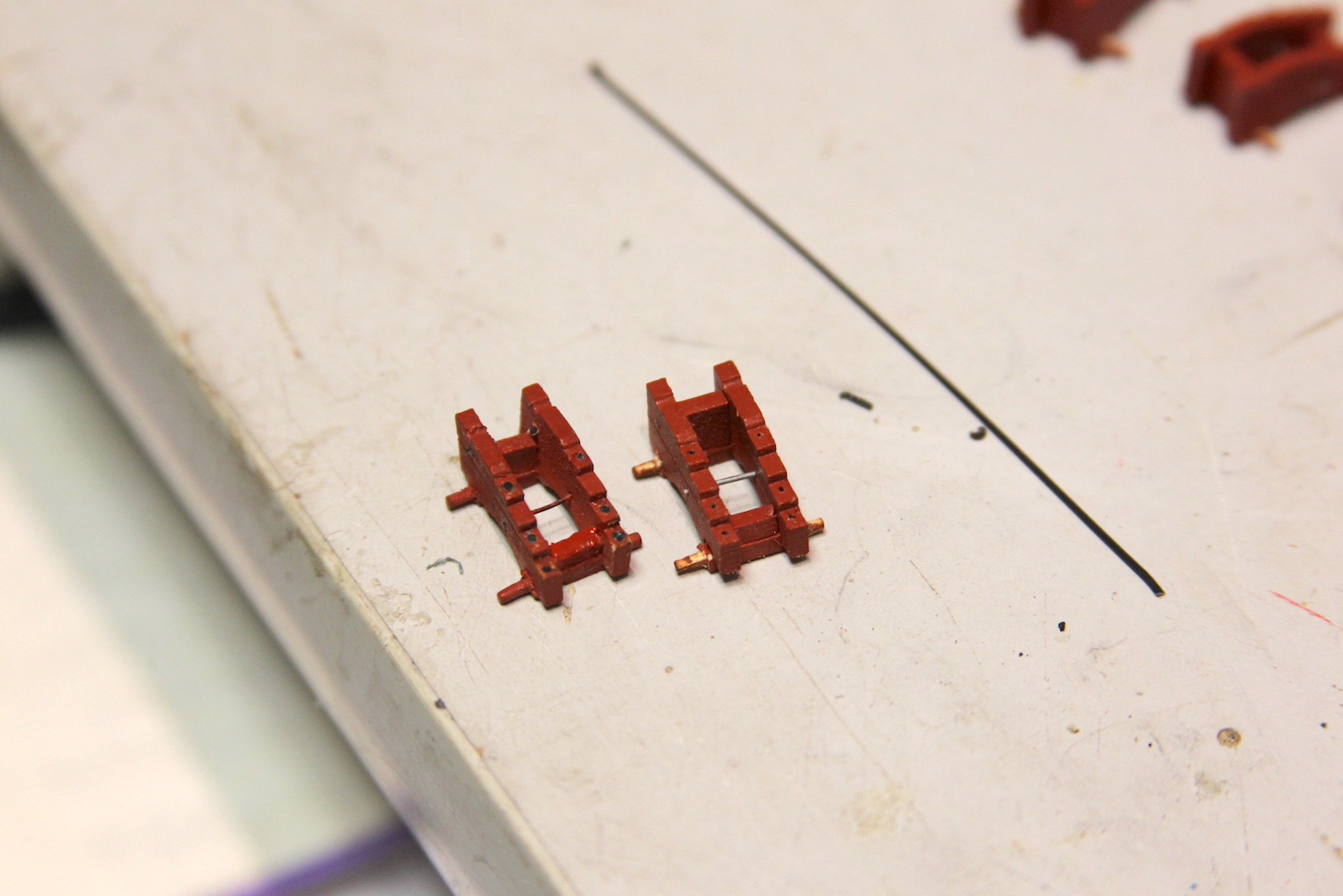
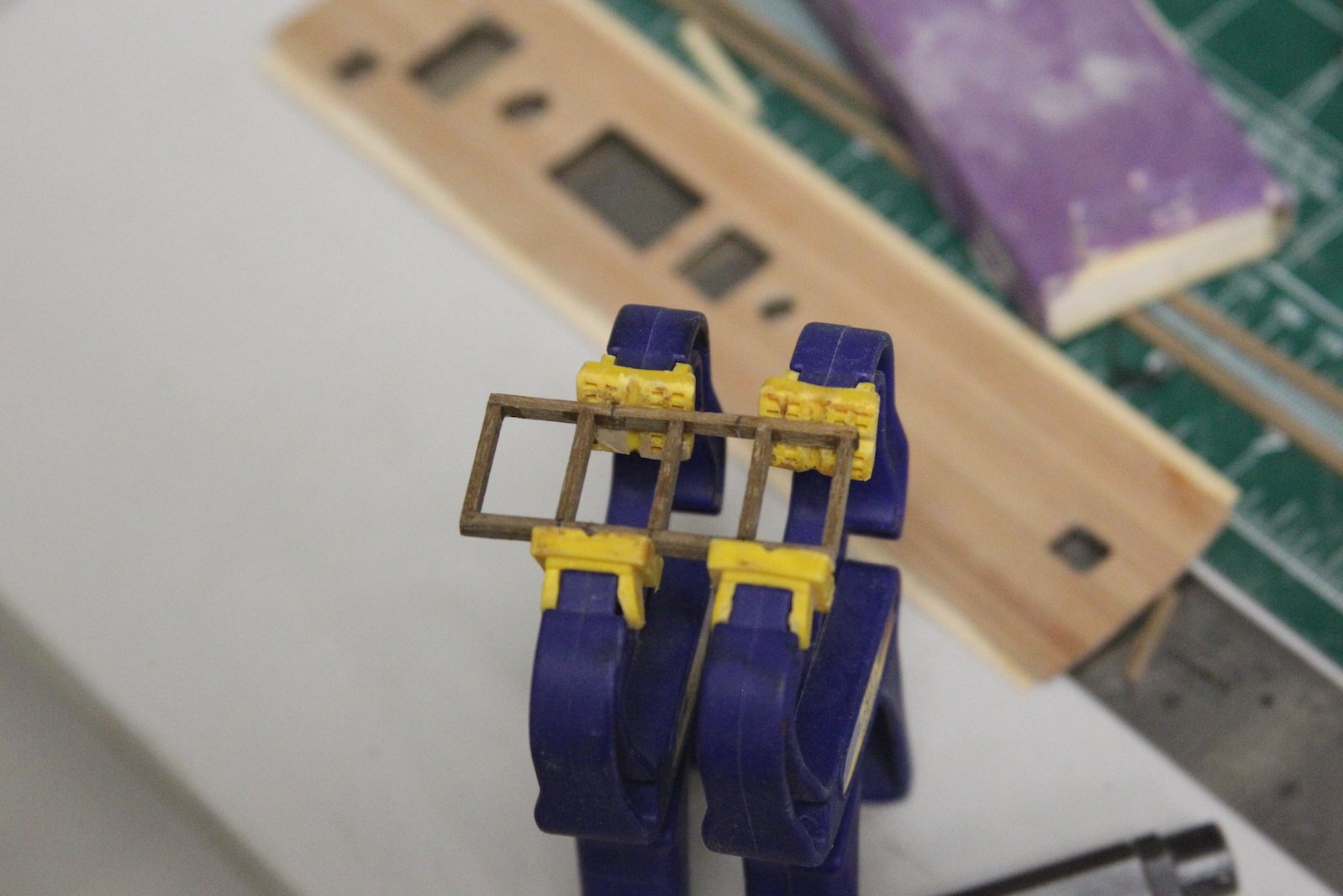
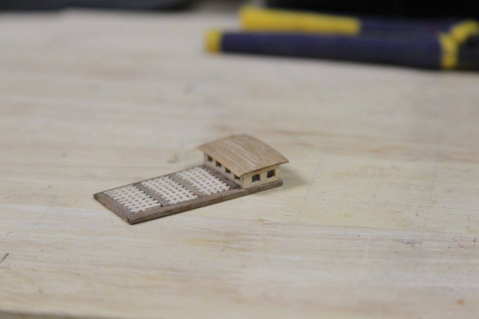
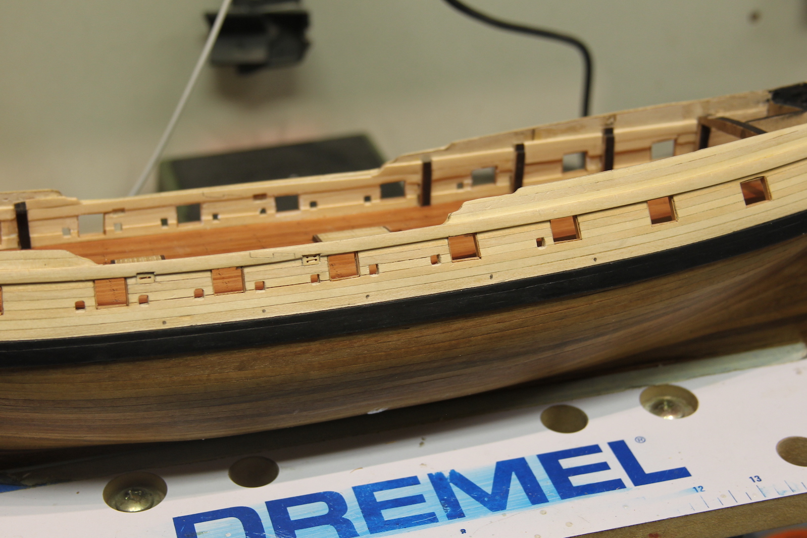
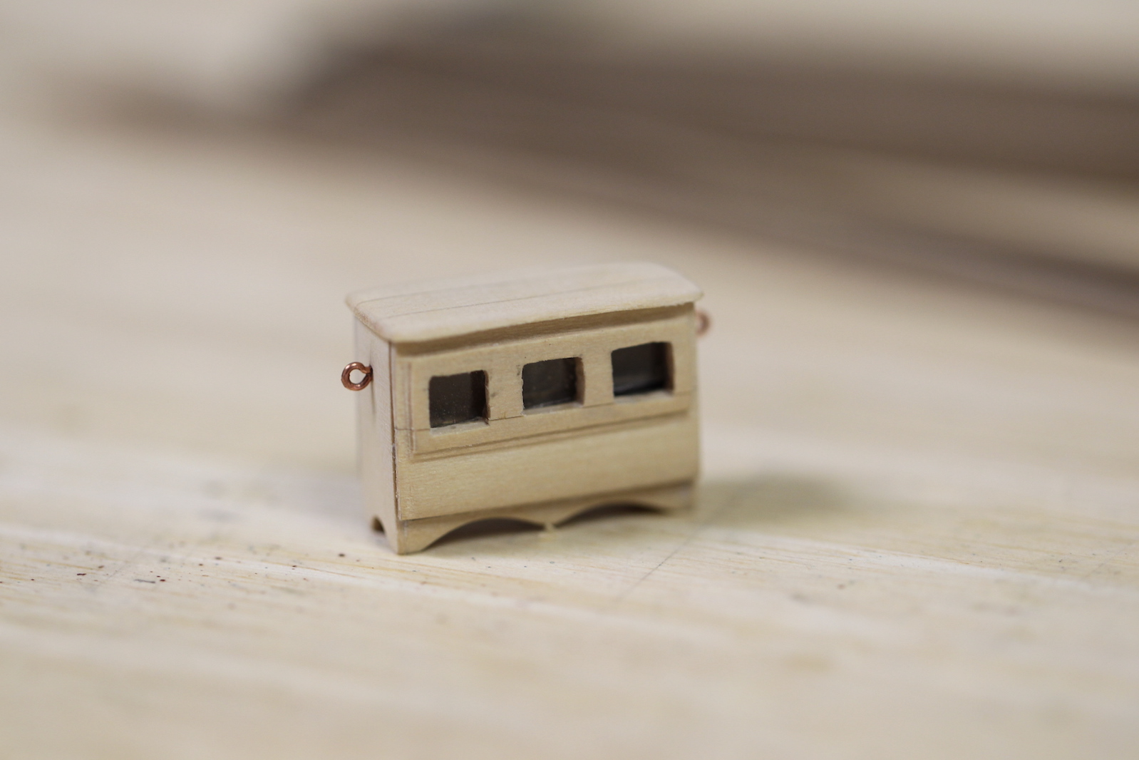
   Here are the assembled catheads and comparison between the kit version on the left and the scratch ones. The catbeams are cut at an angle which facilitates their mounting into the deck. I actually feel like I kinda nailed it getting the catheads to look like they go down into the deck. Pretty happy with the result.  They’re finished off with the bolt in the side.

Gangways

 The gangways are on either side of the waist at the quarterdeck and provide access to the quarterdeck as well as assist with boarding the ship and loading and unloading of materials.  In additional, two gangplanks extend from the gangways along the waist to provide access from the quarterdeck to the forecastle without having to run up and down ladders and navigate the main deck.

  The gangways have a specific curved shape that narrows from the quarterdeck which is framed then planked. I used a thin ply false decking as a templated, then Swiss Pear planking that matches the rest of the deck.

After mounting the gangways, I discovered a significant problem. Well, significant if you’re a 1/64 scale sailor trying to get from the gangways to the quarterdeck.  There should only be a small step from the gangway to the quarterdeck, but because (once again) I’m using a thicker wood for my planking, the “step up” is more like a leap up or a climb up – not so good.  As a solution, I fabricated an additional step up to the decks from the waist.

     The gangboards run along the rest of the waist and connect the gangways to the upper decks and provide that walkway between to the quarterdeck and the forecastle.  They’re pretty straightforward planking with knees attached that brace them to the bulwarks.  They mount just below the gangways and then need a slight curve that matches the curvature of the bulwarks along the waist.

      Finally, treenails are added to indicate where the planks are mounted. You’ll notice the additional step added the the fore end of the gangways here as well.        The ladders that provide access the the gangplanks are a tricky affair. They actually curve and slightly twist to match the shape of the gangway at the top, and then straighten out when they get to the deck. This was a challenge to create at this scale, especially when you end up having only four steps per ladder. I started by using the same materials that I used for the hatchway ladders – cutting notches in the sides into which the steps will fit.  However, the basswood used here a softer wood – which is easy to cut, but makes very precise sanding and shaping quite difficult because it shreds easily.

I felt like I got pretty close on the design, but the second problem the basswood presented was that it just looked weird in contrast to the Swiss Pear decking. I like that contrast between the boxwood fittings and the deck, but I didn’t like it with these ladders.   My second attempt involved Swiss Pear to match the decking and was worth the effort. The denser wood allowed for much more precise sanding and shaping and looked like it belonged.  So – two problems solved, but a third problem created – As I said, I had already made the ladders for the hatchways out of the lighter material – so now they seemed out of place. The only solution was to re-do them in the Swiss pear as well.

Upper Deck Fixtures – The Ship's Wheel

Prior to the 18th century, the rudder on ships was steered with just a tiller – much like you see on smaller longboats or other craft. Sometime during the 18th century (there is some debate as to when) the tillers were rigged to a wheel – as in the cool illustration below:

Courtesy: Wikipedia

The above illustration shows the rigging right below the deck beneath the wheel. However, prior to this iteration, the rigging was above the deck – spreading out to each side of the wheel. That was the case for Swan class British ships like the Pegasus.      The most notable portion of this system is the ship’s wheel of course. The wheel that comes with the Peg kit is a photoetched set of pieces that assemble into a pretty decent looking wheel. However, I have used in the past (here on the Confederacy) a really nice boxwood wheel kit from Chuck’s Syren store.   

      The kit comes with laser cut pieces that need to be shaped properly and a jig that facilitate putting them together. Every piece needs to be removed from its fitting and very lightly sanded to remove the black char around the edges. If this isn’t done it enhances the lines where the pieces are glued together and takes away from the realism.  
     First step is shaping all ten of the spokes. I accomplish this by sticking them in the Dremel chalk and using a combination of pin files and sanding sticks. The handle ends are tapered, but I’ve also tapered the base where the spoke goes into the hub to give them a little extra shape.  Here’s were Chuck providing a couple extra spokes comes in handy – because these things snap off pretty easily if you’re not paying 100% attention the entire time. The spokes are trimmed, then glued into the hub using the above jig to keep them evenly spaced.  The trick here is to use the tiniest amount of glue possible to hold the pieces together.  

      Next the outer rings are added.  The kit provides three outer ring pieces, one of which is slightly larger than the others. However, the original wheels were build with more (and smaller) outer ring pieces – so I followed that route. Then outer ring is then sanded down until it is very thin – just enough to continue to hold all the pieces together.  I added an additional detail of small treenails that hold the outer ring pieces together. Much like the deck treenails, these are simulated by drilling small holes then filling them in with glue and sawdust.  

     The entire wheel is then VERY gently sanded to even out all the pieces and remove any hard edges or misaligned parts.

   The barrel is turned on my Proxxon miniature lathe to form the base, a small ridge, and two ends that will fit into the wheel and the stanchions. The stanchions are carved boxwood – sanded and shaped, then given some texture down the center for a decorative flair. The funky looking “V” shaped piece in the picture below was the stanchion provided in the kit which does not conform to what I’ve seen in the Swan class documentation, however I used it to ensure proper scale. The assembled wheel is positioned (not glued) on the deck to check size and fit.


   Next up, the tiller  – which is attached to the top of the rudder and does the actual steering of the ship. It’s a pretty simple piece cut and shaped from 5mm x 5mm piece of walnut and notched at the base to fit the rudder. The tiller is rigged to the wheel (as shown  in the illustration at the beginning of the post) with rope tied to eyelets on each side of a metal band at the head. 

 For the rigging I used .6 mm rope (since I imagined it needed to be pretty hefty stuff) attached to boxwood blocks which are subsequently fixed to the bulwarks with eye bolts. The rope is wrapped around the wheel barrel five times then through the corresponding set of blocks on the other bulwark. The wrap is attached to the barrel with a bolt that serves as a stopper which limits the amount the rudder can be turned. This TINY (.020″) bolt was very difficult to get into place without getting glue all over the rope and discoloring it.

   The wheel is permanently fixed into position. Notice I’ve also fixed into position the binnacle that was finished earlier.  It was necessary to fix this into position to ensure the wheel was in the proper place.  The back end of the binnacle can be (and is) pretty close to the mizzen mast. However, there must be sufficient space between the binnacle and the wheel for the helmsman to stand and maneuver.  This little spacing detail is something that is often overlooked (or poorly accounted for) in many plans and builds.      Finally, the rudder head housing it put together with boxwood and veneer strips to match the look/feel of the carriage house just on the other side of the mizzen. I also wanted to ensure I had enough room between the rudder housing and the stern to put an ensign staff clamp (more to come on that later).  

Deck Fixtures – Hatch Railings

The open hatches on the deck which contain stairs also need to have some sort of safety railing around them or else the sailors would surely fall to their discomfort. These railings are often made by simply mounting long eye bolts and running a string/rope along them – much like you’d see entering a movie theater.  Since this is neither particularly accurate or (more importantly) cool, I wanted to elaborate a little.

I fabricated my stanchions out of these T-Pins that I snapped off. I wanted something with a pointy end that would facilitate mounting.  I then soldered some rings to them.

     After running around trying to find tiny little beads or something to serve as railing toppers (including raiding my teenage daughter’s stash of beading supplies) – I onIy came up with about half of what I needed. So – I made the rest on my own by using half-dried clumps of acrylic paint, rolling them into tiny balls, and then letting them dry.  Then painting over them with Model Master enamel paint.  The toughest part was getting all the little balls perfectly round and the same size. Pretty hard to tell the difference if you ask me…

For the railings themselves, I’ve seen metal/wire used and I’ve seen rope.  I decided to split the difference and use this pretty cool little cable wrapped wire I had lying around. Although not entirely accurate, I think it’s important to remember that while we all strive for a certain degree of accuracy, sometimes it’s also important to remember that these are our pieces of art, and that often calls for some deviation for our own benefit.

We all also seem to have our own “Mr. To-Scale Guy” with whom we test our sizes, etc.  My guy comes from an old S-scale (also 1.64) Train set.  He looks like that because he was pushing a lawnmower at one point.

On another note – these macro shots remind me that I’m going to have a lot of dusting and cleaning up do do.  Sheesh.  Either that or I need to just start using a crappier lens.

The Transom

 The transom which houses all the cool decorations, windows and Captain’s cabin is by far the most notable and visible areas of the ship.  For that reason, it’s imperative to get it just right and as accurate as possible. That’s no easy feat given the sheer number of details.  

       Before I could get too far along there were some significant flaws that needed to be addressed.  On my ship, the area where the transom would meet the stern was rounded – where as the NMM plans clearly show that area as straight then forming a concave curvature as it meets the helm port, rudder, etc.  So my first job was to reshape the back end of the ship.  

The other significant flaw was the sides of the transom itself – as you can see in the first photo, they just hang out over the edge of the stern and are cut off, which makes no sense at all.  Every transom (especially based on the plans above) meets the sides of the hull in some fashion. It was almost as though some extra piece were missing.  At any rate, some reshaping was definitely required.  

   After reshaping, I added the paneling along the stern that separates the cabins from the helm port which creates a very important area – the name.  

      Though the reshaping of the transom both looks much better and is more accurate, it does create a subsequent problem that needs to be fixed – the fitting of all the carvings and decorations. Obviously, the kit provided decorations (which are photo etched brass) are made to specifically fit the kit shaped transom. So – how to fit the decorations into a smaller, differently shaped area?   First, I painted them with a few different layers and shades to try and create a more three dimensional look – the same technique as I used for the quarter galleries.
Then, I installed the windows – because I know that the window locations are fixed and will serve as my benchmark for placing the rest of the decorations.  Once again as with the quarter galleries, I am using the thin microscope cover glass as ‘real window panes’ in my windows.  

  Then, I installed the windows – because I know that the window locations are fixed and will serve as my benchmark for placing the rest of the decorations.  Once again as with the quarter galleries, I am using the thin microscope cover glass as ‘real window panes’ in my windows.

  The decorations themselves come in layers to facilitate somewhat of a 3D ‘carved’ look. I used a technique to add to that later. But first, I cut apart each decoration so that it is a separate piece which allowed me to place them individually. I started withe the Pegasus centerpiece, then added the two soldiers on the outsides (the poor soldiers had to be ‘trimmed’ to fit the different shaped transom) and then individually placed elements to fill in the gaps in between.  

    To further enhance the ‘carved’ effect, I filled in a small syringe with relatively thick yellow ochre acrylic paint and attached the tiny nozzle used for silver soldering. I added the painted to raised areas of the carvings to raise them even further.  This took a lot of time and patience and some scraping off of extra painted when my fat-fingers splooged out too much paint on occasion.    

  Finally, lining up the letters was an incredible pain in the ass.  First, the laser cut letters were TINY, and very difficult to remove without damaging them. Then – they were very challenging to paint, and finally – SUPER challenging to line up straight and with proper spacing. It took me almost as long to get the letters on the ship as it did to do the rest of the decorations.  Unfortunately, I’m pretty terrible at painting letters or I’d have probably just abandoned the laser cut stuff and painted.  

       However, at the end of the day (though they’re not perfect) I think they’re pretty darn close. Of course the macro-lens shots show all the flaws, and I overall it looks better to the naked eye than represented here.      Next steps were to create a cap rail along the transom so it would match the rest of the ship.  I’d seen builds with and without this rail, and although I knew it’d be a bit of a challenge to get right I wanted to give it a shot.  I started by thinning out a 5 x 2 mm strip of basswood and soaking it, then using a hair dryer to bend and mold it along the curves. I used the gel gorilla glue CA to glue it down as I went along.  

        It was a pretty slow, delicate process not to dry it too quickly and snap the wood, but it was worth it in the end.  After some trimming of the edges toward the bottom where it meets the wales, a little bit of filler in some gaps, and sanding it was ready to paint.  After it’s all said and done, I am pretty pleased with the overall results.


The Rudder

The rudder steers the ship of course.  But as ships got larger and more modern (relatively speaking) rudders got a little more complicated, becoming pretty ingenious bits of engineering.  In the case of the Peg, the rudder capped up through the decks, was attached to a tiller (the long arm that moves back and forth with the rudder), which was then attached to a ships wheel.

First, the inside of the rudder is tapered to allow for a turning radius as the rudder moves back and forth.  Then, the rudder is copper plated below the waterline matching the rest of the hull. Although the copper plates used for the hull were just wide enough to fit the rudder, I wanted to maintain the same kind of bricklayer stagger I had with the hull, which present some challenge but is more accurate.


   The rudder is attached to the hull with a basic hinge connection. The ‘pintles’ are strips bolted to the rudder with pins protruding. The ‘gudgeons’ are the corresponding strips bolted to the hull with a small eye hole that accepts the pintle. As you can see above, a small area is cut out from the rudder to facilitate this hinge while still allowing the rudder to be relatively flush with the stern post.

  The rudder also contains a ‘spectacle plate’ mounted to the rear. This plate has a chain that will connect the rudder to the sides of the ship – this will be attached later in the build as it has a tendency to snag on tools and things during the build.  The chain serves as both a limiter on how far the rudder can turn, as well as an emergency steering tool if the tiller or wheel are damaged.

    Anyway – the spectacle plate is created using a square strip of brass that’s bent at two 90 degree angles then sanded down to fit a corresponding slot on the back of the rudder.  Two brass rings are then soldered to the corners of the plate which will later accept the chains.

    Everything is ‘bolted’ to the rudder and hull using miniature nails. I use a very specific .020 inch nail here from a company called “Micro-mark” because they have rounded heads that look great as bolts.

  A feature that you rarely see on model ships is the “rudder coat.”  This is a tarred piece of canvas that loops around the top of the rudder as it extends through the helm port to the decks. This canvas protects the upper areas from water that may slosh up from the stern of the ship.  I’ve simulated my rudder coat with an old piece of simulated ‘leather’ that was left over from my Stagecoach build.

    The piece is cut to fit then glued one side at a time as I wrap it around the rudder then stuff it up through the helm port. 

The rudder is finished off by blackening the top gudgeons and pintles and painting the bottom ones. The bottom ones were coated with copper much like the hull. However, since they were coated slightly differently than the full plates, the color is slightly different as well.  I chose paint from a company called “The Army Painter” which specializes in medieval figures, etc. Their paints do a great job of simulating metal colors.

Bitts & Pieces

I’ve been working on a few things simultaneously over the holiday break.  I’ll have more updates soon on the rudder and transom.  But I’ve also been catching up on some of the miscellany of bitts and rails and other items. As always, everything ties together – so using a thicker deck and increasing the bulwarks affected the roll of top rail that sweeps into the waist.  Instead of trying to match it to the plans, or even match it identically to the original plans or other sources, I instead took what the build gave me and worked with that.

I used a solid piece of cedar scrap to draw out what the rail would look like, then carved/sanded the pieces to fit. Admittedly, I’m not much of a wood carver, so my little bit of saving grace is that it’ll all be painted black so my inevitable flaws will hopefully be covered.

The the strips along the wales and railings have some decorative elements to them – so in order to achieve that I sanded down some carving tools to create a few different scrapers.  The strips themselves are boxwood – split down the middle, sanded even, then carved and painted before mounting. 

  After the bitts are added along the rail, I filled in all the gaps with wood glue before painting.  

The Upper Decks

Now that the guns are mounted and most of the main deck fittings are in place, I can move on to the upper decks – the aft as well as the foc’sle. The final piece of main deck furniture was the gallows – which was not actually used for hanging or any such punishment. Instead, it was a key feature on the main deck that braced the boom or other masts and stays.  On the Peg, the gallows will serve as a brace for the extra masts. For the most part, the gallows is a relatively simple affair, but I took it as an opportunity for a little bit of embellishment.

As for the foc’sle, I used a little different technique for planking.  Instead of mounting the false deck and then planking it after it’s mounted, I chose to do the planking first.  My reasoning: I wanted straighter lines for the treenails, and I knew I’d only be able to achieve that with my drill press.  So I planked and marked off the fore deck, drilled and filled the treenails, then mounted it.  I also soaked and bent the margin planks a little bit based on the shape of the foc’sle.

This made it a little more challenging to shape and add the margin plank – as usually this process is done the other way around – margin plank first, then other planks fitted.  So, I measured out the margins using card paper as a template, cut the scarph joints, and then fit it all together.

This method of planking the foc’sle ended up being a bit more challenging that I’d hope, so I reverted make to a more traditional method for the aft upper deck.  I planked SOME of the false deck, then mounted that – shaped out the margin planks, and filled in the rest of the planking.  But… before I could get to that… test fitting the rear deck revealed a major oversight on my part.  

I totally screwed up the spacing of deck elements because I didn’t think far enough ahead – an error I discovered when I placed the upper deck in the aft of the ship.  As I’m sure most of you know, there can be a pretty big downside when it comes to half following the kit plans and half following the FFM and other builds.  My particular problem occurred with the pumps.    

My big mistake – was following the kit template / false deck with it came to the locations of all the hatches – but then following Dan’s more accurate build/locations when it came to putting in the pumps.  I wish I took more ‘before’ pictures – but I was too irritated and just started fixing. But basically, when I test fit the upper deck in place then looked down through all the holes/hatches –  the larger grate just aft of the pumps is about two times too large – so the the pump handles extending over it go RIGHT underneath the upper hatch that’s supposed to be fitted with a ladder.   Doh.   So – even if I were able to fit a ladder in there – folks would be descending right into the pump handles.  Many “potty words” were uttered as I tore up deck planks and fittings.  

After tearing everything up, I reduced the size of the hatch by half, patched the deck to fill in the gap, shortened the aft pump handles and remounted them into the posts. The good news is – the view of all of this will be severely obstructed by the pumps, subsequent ladder once it’s installed, and various rigging and accouterments.

         Once again – the reminder here – you can NEVER, ever, think too far ahead.      After the fix was completed, I was able to continue with planking the aft upper deck.  The deck narrows toward the stern, which requires a very particular kind of tapering and ‘drop planks’ to facilitate the taper. The drop planks are created from a double wide swiss pear plank that’s measure, shaped to include the angle along the margin plank, and a square joint that fits the next plank. You’ll notice from this deck, as well as the hull planking, that shipbuilders always avoided a sharp taper as butted boards were easier to seal with caulk.  

Once the decks were planked, I was able to build out the aforementioned hatch coamings, then add the stairs.  Just to the fore of the stairs are two hatches called ‘scuttle lids’.  The kit shows them as small grates, but I chose solid planked lids as this was a more likely fitting.  Also, as I discovered with the small stove vent grates on the foc’sle – the smaller grates aren’t thin enough for my liking and look a bit chunky.

      As a reminder, I’m using Swiss Pear wood instead of the planking that came with the kit. It’s much better quality wood – and provides a really interesting coloring that I like. However, the Swiss Pear is much thicker than the provided strips. This is great as it allows for additional sanding and a higher level of smoothness can be achieved.  However, the added thickness means I need to build up the height of the bulwarks (the sides of the decks) to accommodate for this.     I soaked and bent strips, then let them dry to fit.  The bow strip was made with one continues plank of wood. After they were shaped, I added the strips to the inside of the bulwarks, then planking to the outside. I sanded in the inside and outside to match, then repainted.  

Guns & Carriages

Obviously the armaments are always an exciting area for a ship build – both for the builder, and for those who see the ship. Since they end up receiving so much scrutiny, it’s important to have a well thought out plan to achieve the accuracy and look you’re going for.

Although the rigging of gun carriages varies significantly based on country or origin and time frame, there are a few basic elements that are consistent: a breeching rope, out-haul gun tackle, and in-haul gun tackle.  The breeching rope attaches the carriage to the side of the ship with enough slack to allow the gun roll backward (recoil) once it is fired.  When the gun is far away from the gunport, the out-haul tackle (often just called the gun tackle) is used to pull the gun toward the hull.  The in-haul tackle (also called the train tackle) is used to pull the gun away from the gun port so that the cannon can be reloaded.  The latter is typically only used when the ship is in battle – otherwise sailors would likely be constantly tripping over them during daily movement. I’m choosing to display the Peg in a peaceful mode shortly after her launch, so I won’t be including the train tackle in this build.

I started by rigging up a ‘test’ gun in the aft of the ship. This gun’s rigging won’t really be visible as these rear guns are behind cabin doors and under the quarter deck and allowed me to figure out how I wanted all the guns to look.

The original Peg launched in 1776 calls for 14 guns even though there are 16 gun ports. The second Pegasus (launched in 1779) reportedly had 16 guns.  Even though I’m building the original – I’m choosing to include all 16 guns so that all the gun ports are filled.  Note that the two foward-most ports are not gun ports, but serve a different purpose.        

With 16 guns to build, it becomes an assembly line style process. Each gun requires a breeching line withe an eye bolt and ring attached that’s looped through the rings on the carriage then attached to spirketing (inner gunport wall). The breeching rope is also looped around or otherwise attached to the “button” on the back of the cannon.  The side gun tackles have two hooks tied to took blocks (pulleys) and attached to the inner gunport and then the cannon carriage (as illustrated in the above drawing). So – that’s 64 hooks tied to 64 blocks then connected with 32 ropes. Each of the blocks also had to be drilled out with a hole large enough to accept the rope. Three different sizes of rope are used  – large for the breeching rope, a medium sized rope for the side tackles, and a very thin rope to knot off the loops, hooks, blocks, and eye bolts.  

       The breeching ropes have one eyebolt and ring attached and are fed through the rings on the carriage before the second eye bolt and rings are affixed. The cannons are mounted in place by attaching the eye bolts to pre-drilled holes in the gun port sides. Then the side tackles are ‘hooked’ to the upper gunport eye bolts and complimentary eye bolts on the carriage. Finally, the side tackle ropes are pulled taught and the remaining rope is coiled next to the gun.  

     With all the cannons mounted, I can finally add some of the lower deck fixtures that were pre-made long the way.  And lo’ and behold, she’s starting to look like a real ship!  

    Next up I’ll finish off a couple of remaining lower deck fixtures (such as the gallows) and then start working on the mounting and planking the fore and aft quarter decks.

Quarter Galleries

   Quarter galleries are a fun, prominent feature of most ships and adorn the sides of the stern castle.  They basically served as little balconies in most cases, though with smaller ships such as the Peg they were often just windows.

   The plans for the Pegasus (and associated fittings) call for flat quarter gallery windows, which although sometimes accurate, don’t provide the most pleasing profile. So based on some modifications made by fellow ship builders, I decided to create a more three dimensional look – which is suggested by the three paneled profile from the National Maritime Museum plans. 

   I started by adding some additional dimension to the frieze and carvings. The Amati kit uses a couple different layers of photo etch that are subsequently stacked on top of one another to try to create carvings, but I felt I could add a little more. So I coated the photo etched pieces with yellow ochre air brush paint, then I went through and carefully dabbed some areas with bits of yellow ochre acrylic and then let it dry.  Then I went through and air brushed a VERY light coat of white, then back over it with Vallejo’s yellow ochre “air”.  The intent was create an impression of carving. 

   On to the quarter galleries themselves.  First step, I marked out where they’re going to be, then made room with the trim, drilled out the space to create a cabin inside, then painted it black. Next up, I cut out and shaped some balsa affixing it to the top and bottom of the quarter gallery frame to give it some dimension.  One of the most difficult and delicate parts of this operation was separating the window frames which were laser cut as one piece. I used a jeweler’s saw with my thinnest blade and very gentle cutting to separate the frames.  The frames are then realigned and glued into place with any little gaps filled with “wonderfill” wood filler and then the whole thing is painted black and the photo etching is added.  I didn’t take photos of that bit, but extra care is needed to bend the pieces to fit the now three dimensional gallery.

    Now, my favorite part!  I finally figured out that the best way to shape my little microscope slide covers (used on the Companionway housing) is to carefully hold them against the belt sander.  I marked the shape I needed with a sharpie and just barely let it touch the sander which was fast enough to not shatter the piece and also half melt – half sand the glass into shape a tiny bit at a time.  It’s a good thing I ordered a hundred of these things, because I went through five or six with each effort to get one right. It was then glued in place using white glue that dries clear. I actually prefer fabric stitch glue here because it’s tackier.  The galleries are just sitting in place for the moment and will be permanently mounted later.

      The glass is a bit of a pain obviously, but ended up looking really good.  I purposely took pictures with an angle where the light reflected on the glass so you can see it, but the photos don’t really do it justice. Really clear straight on, then catches the light.

Coppering the Hull

One of the most interesting (to me) aspects about ships in this time frame is that it marked the beginning of sheathing the hull in copper.  Pioneered by the Royal Navy in the 18th century, coppering the hull was an effective way of protecting the wood from the corrosive effects of salt water.  The British were not the first to do this however – as the plating of hulls has been linked back as far as the ancient Greeks who used lead instead of copper.

   Nonetheless, I’ve never coppered a hull on a build before and it felt a daunting task.  First steps are to measure an accurate and straight waterline.  To do this, one needs to make sure the deck of the ship is properly parallel to the horizon both port to starboard and forward to aft – this is how the ship would sit in the water with a balanced ballast (weight in the bottom of the hull).  To do this, I set up a couple of different kinds of levels, then manufactured a waterline marking using a table tripod with a pencil attached.  Obviously it’s critical to make sure the pencil mark is consistent along the hull as well as on both sides.  The subsequent pencil mark is difficult to see on the walnut, so I marked it off with Tamiya model masking tape. 

  Fortunately, the copper plating itself that comes with the Peg kits is really nice stuff. I’ve seen a variety of quality and methodology during my research, and this stuff is tops. The plating comes in pre-pressed and creased panels wherein each individual plate is stamped with a bolt pattern and can be removed easily by just wiggling them back and forth. This affords the opportunity to snap them off either in singles or a strip.  The bolt pattern is directional and specific to either side of the ship, so I marked the plastic to reflect the proper side. 

   The plating itself is done parallel to the stern and each row follows the lines of the previous as you work your way up from the keep with the absolute slightest overlap from the previous row. The plates begin to angle as they follow the lines of the hull from stern to bow, and some very, very tiny adjustments to the angle need to be made along the way. Once the plates reach the waterline they’re trimmed off to create a straight line. For the keel itself (and the bow and sternpost) I used a copper strip which will then be marked with a bolt pattern and the strips along the sides are trimmed flush. The bottom of the ship will eventually have an additional “false keel” over the copper. This was done in case the ship ran afoul on rocks or other items in the water – the false keel was much easier to replace than any damage to the hull itself.

 
On the starboard side (which I did first) I started to get a little nervous as to how the plates were overlap at the bow and stern, so I patterned out the stern to get an idea of how the strips would go.  From there it’s just a repetitive – and very slow – process of ensuring that each plate is done consistent and overlaps a proper amount. 

  After the entire hull is done, an additional ‘batten’ is added along the waterline to seal the copper – I’ve represented this by using a walnut strip to match the color of the exposed hull planks. Much of the time this area is panted black along with the main wales, but I’m choosing to leave it as it’s natural color. From there, it’s time to polish up the copper.  I started by using a 600 grit soft sanding sponge so I could get into the nicks and crannies without fouling up the copper. This is done VERY lightly so as to not catch the corners of the plates and bend them out of ship (which I still did on a couple of occasions).

  Second round of polishing (to clean out the lines where the plates meet one another) was done with a soft wire brush attachment on the Dremel tool. This was done at medium speed and very lightly going over each plate barely letting the brush touch the plating.  Here’s a shot halfway through the hull to see the before/after effect. 

 Here are the final shots of the copper plating after buffing with a cloth and sealing the batten with tung oil. 

    Next up will be determining what to use to cover/seal/protect the copper from tarnishing too much over the years. Particularly since this ship will be a ‘straight off the dockyard’ representation rather than weathered like I did with the Santa Maria. 

Battens & Hatches revisited

   Sometimes during a build you just have to go back and fix some things that aren’t quite right or accurate.  Every build is a combination of accuracy, artistic license, and level of effort into details. For instance – how much time do you spend on details that aren’t likely to be noticed?  

   Along with maintaining this blog, I’m also part of a group called the Model Ship World, a forum made up of ship builders and hobbyists from all around the world with varying degrees of skill and interest.  Some of the very best master builders, authors, and researches are part of the membership which is sponsored by the Nautical Research Guild.  After my last post about guns and carriages, one of the members of the forum pointed out that my hatches and battens weren’t accurate in their representation.  As you can see in a previous post and pictured below – I had the crossmembers extending all the way out to the coamings (the frames of the hatches), which is not correct. The battens need to be constructed in a way that they can be removed – as seen in these hatches on the HMS Victory:

  Now granted, the casual observer is not likely to notice the difference, or even realize what they’re seeing.  However – the hatches are very prominent parts of the ship and so I decided that getting them “correct” is pretty important.  The exercise also reminded me of why I started building model ships in the first place – to instill additional patience in the things I do and reinforce the idea that taking some extra time to achieve correctness is well worth it.  Overall, it took a full day (about 8 to 9 hours) to go back and re-do all the battens and hatches correctly.  However – for a ship that is likely to last many years and hopefully be passed on from generation to generation, what’s an extra day?

Sometimes it’s pretty easy (at least for me) to get caught up with the idea of just getting something done and lose the importance of the process. The second go at the hatches is much improved and very much worth the extra time and effort.

Lower Deck Fixtures – Guns and Carriages

      One of the most prominent features of almost any Age of Sail vessel is the armament. The guns and carriages always immediately draw the eye and so it’s pretty important to get the right amount of detail and accuracy.  Here’s an illustration courtesy of castyouranchor.com

     Once again (sounding like a broken record), the fittings that come with the kit are quite fine, and are both detailed and accurate. However, I wanted to go the extra mile with this vessel, and ordered guns and carriages from one of my favorite suppliers – the Syren Ship Company run by master ship builder Chuck Passaro.  Along with the guns, I ordered the period correct emblems as well. 

     The pegasus features 14 six-pounders on the main deck, which begs for an assembly-line style of production when fixing/weathering the guns and putting together the carriages. I created an assembly jig out of leftover scraps for the actual carriage builds. A jig is essentially a piece of equipment that allows you to align and build something the same each time.  I also used the boxwood pieces from which the carriages came as a jig that allows me to score the sides of the carriages and the wheels – as in reality they were multiple pieces framed together and not one-piece sides. 

   As you can see from the above picture, the cannons are turned brass – so require quite a bit of work to get them to look authentic.  But first – we’ll talk about the carriages: I assembled most of the parts individually but did not glue all of them together. First, I wanted to figure out how to create the “quoin” (see illustration above) that adjusts the height of the cannon. I cut some extra boxwood down into strips – boxwood is important again here because of it’s density which allows you to carve or sand very small pieces without it falling apart in your hands.  I fed about 3 or four inches up into the drill press, exposed a quarter inch at a time, lathed out a quoin and cut it off, then pulled the boxwood down another quarter inch and repeated the process. The fourth picture is my process for sanding down the char (the leftover burn marks that occur when pieces are laser cut) off the wheels.  I have a devil of a time keep them round when I do it by hand, so I inserted a bamboo toothpick into my chalk and put the wheel on.  I then VERY gently hold my fingernail against the wheel to get it to spin (rather than push it hard onto the tooth pick) and then barely brush it up against the edge 200 grit sandpaper that’s hanging over the table. Couple of important notes:  the Dremel is on is lowest speed, and it’s important not to do it against a hard surface, but rather let it brush against a flap of sandpaper. 

  After the main parts of the carriage are assembled, they’re painted with Red Ochre using an airbrush to get as even a coat as possible while still being able to see the defined areas.  The carriages are held together with bolts – so it took a little bit of noodling to figure out how to simulate those bolts – pins, wire, or nails would just be too big and difficult to blacken.  So I settled on hard monofilament from a brush. My first attempt was pulling strips from an old broom in the garage, but I felt they ended up being too big and appeared out of scale. Second attempt is from an old golf club brush. Here are the two attempts side by side, then the carriages with the bush bristles glued in making them look “hairy”.

After that – it’s time to get the guns ready for mounting. The guns start out as shiny turned brass, so need to be weathered to look authentic. Step one is gluing the tiny (and quite fiddly) little emblems to the guns and drilling out a hole in the pan for lighting the cannon. I chemically blackened the brass and then sanded off much of the soot – returning them to brass, but leaving some of the blackening in the crevices and lines. This is an extra step that I liked during my experimentation phase as it ends up giving a little extra texture/variance to the end look that appeals to me. I then airbrushed all the guns with a mixture of Vallejo’s brand of black and grey black thinned down with a black wash. This gives a nice color and the thinness allows the emblems and details to stand out really nicely without getting pounded down with paint. This first shot is pre-weathering.

Finally, Tamiya is my preferred weathering product and I gave each gun a light brush of “soot” to dull the paint, then “rust” to bring out the edges. My goal is to give the guns some character but not make it look as though the crew has neglected their duty in maintaining the equipment.

After the guns are prepared, it’s back to the assembly line to put it all together.

Wheels and quoins are mounted onto each carriage followed by a series of eye bolts that will facilitate the rigging later. The eyebolts are chemically blackened then touched up with paint. The middle eye bolts have rings attached which will hold the breaching rigging. The guns themselves are then mounted and bolted down using the same “bristles” from the brush to serve as bolts.

Here’s a close up shot of the final gun/carriage combination nice and weathered. The guns are all set aside until I can get some rigging put together, then they’ll all be mounted to the main deck later along with the other main deck fittings. 

Upper Deck Fixtures – Aft Companionway

   Much like the other fittings, the clerestory-style companion top that goes on the aft deck didn’t much look like the ones I’d seen from other builds and swan class research.  It seemed pretty easy (relatively) to construct one, so I put it together with boxwood.  Created the grates first, used the far aft opening to measure out the top, then drilled the windows and filed them square. A leftover laser-cut bit from a previous build gave me a good template.

One thing I wanted to do a little differently from other builds: the window panes. I typically use some sort of acrylic sheet or plastic lining to create the windows, but then I remembered reading in a model train forum that “nothing looks like glass like glass looks like glass…”

So I ordered these little guys – .013-.017mm covers for microscope slides. While they’re very cool – they’re a MAJOR pain in the keister to work with because they shatter almost instantly. After completely unsuccessfully trying a handful of methods to ‘cut’ them (even trying a glass cutter), I ended up using forceps with the ends tape to brake them close to the right size, then gently sanding down the jagged edges with 400 grit sand paper. Probably took more time than reasonable given that the end result is unlikely to be noticed by most people. But – although it’s very hard to tell the difference in photos – I notice the difference, and that’s cool.

The grate/companionway gets set aside with all the other little furniture pieces until it gets mounted on the deck later.

Lower Deck Fixtures – Brake Pumps

   While the larger cisterns (pumps) were for stale bilge water that collected in the hull, there were also smaller brake pumps for pumping up water from the hull to be used for washing down decks, fire-firing, and providing water for distillers.  Here’s an excerpt from plans available from the National Maritime Museum in Greenwich, London.   

   Regardless – there are no mention of these pumps int he Peg plans at all, which is certainly an oversight. Particularly since however detailed a builder chooses to (or not to) make them, these deck fixtures are almost always a cool addition.

    My brake pumps consist of a wooden dowel that is drilled out then planked on the sides.  I left a little knob on the bottom of the dowel so I could fit it into the deck. I chose to plank using the thin leftovers that were supposed to be used for deck planking to mix up the color a bit and simulate the elm with which they were typically built.  Elm is notable as it is able to sustain continual immersion for long periods of time.

    As you can see above, I cut one dowel for both pumps, split it in two, then drilled out the centers. The handles (called brakes) and the ‘cheeks’ which held the handles were shaped and carved from boxwood. After they were formed, I filed down the insides of the cheeks to create a slot in which the brakes could sit and form the lever for the pump.

   Pumps are finished up with a brass tube for a spout, wire eyelet for spear (that goes down into the pump), and a metal strap to hold it all together.  These will be set aside with the other deck fixtures ready to mount later.  

Scuppers, Rails & Paint

    The scuppers on a ship are essentially the drain holes off the deck. Several holes line the outside of the waist of the main deck so when water gets on the deck is drains back out. They’re scaled out to be about 1.5 mm on the 1/64 Peg, with the exception of the scuppers that line up with the cisterns and the pump dales which are slightly larger.

     This seems like a pretty straightforward part of the build – you just measure out the locations and drill the holes.  Except for the fact that any time you drill holes there is exactly zero margin for error, and you have to get the angle perfect so the scupper hole goes from the black strake (remember it’s not actually black) up through to the deck – right where it meets the spirketting (the plank that runs along the base of the gun ports and joins the deck). It doesn’t really matter which way you drill I suppose, but I drill from the outside in – since the outside scuppers are much more visible and would be noticeable if they are not exactly in line.

   Next step is installing the rail along the outside of the gun ports that is part of the “stuff of the topside” or planking that makes up the outer gun ports.  One of the key aspects of ship building is the need to devise your own tools and/or instruments for specific needs. In this case, I needed a way to scribe the rail to give it some texture, so I took a 90 degree chisel and notched out a groove so I could scrape along the strip.

   From there, it was on to painting. After quite a bit of research on the exact paint scheme of the Pegasus, I came up with ambiguous answers at best. There are definitely some consistencies in terms of how the ships were painted, but no definitive answer on this particular vessel that I could find. So, I used other Swan class and late 18th century British ships as a guideline and went with my own scheme. Yellow Ochre is pretty standard for the masts and other key parts – some of the ships left the gun ports natural, but most appeared to have those as yellow ochre as well.  The inside of the gun ports was always red, but getting the shade is a little tricky – too bright and it looks weird, but too dull doesn’t stand out. I went with a Vermillion mixed with an earthy red ochre.  Finally, the sides ranged from black to blue to natural, but I felt it needed to be something that would set off the frieze (the decorative bits that will eventually be added along the side of the ship) so I went with a blue gray. 

   My paint method involved masking each section off and laying down a few nice even light layers with an airbrush, then spending a good 8 to 10 hours going over each section to tighten up the lines and touch up any areas that needed attention.

Planking the Gun Ports – Inner

    Next up, planking the inside of the gun ports. Similar to the outside, the inside is planked with a couple of different sizes and widths of boards that all serve pretty specific functions.  The lowest plank is wider and thicker to facilitate the scuppers, the mid planks are thinner which allows the guns to be rolled up closer to the ports, and the upper planks are wider and thicker again.

    Before I could commence planking however, I needed to take care of the posts in the middle of the ship.  These posts are in place to temporarily bolster the gun ports as they are mounted to the ship. So – here’s the thing:  completely not sure what I was thinking planking the main deck all the way to the outsides before this part of the build. If I had to guess, I’d say that I was just a little excited to see how the Swiss Pear was going to look and just rolled on through the planking.  Anyway – what’s done is done – so I cut off the posts, pulled up the planks, and replaced them by forming some card stock and cutting out the planks from wider pieces of Pear and adding a scarph joint.  A scarph joint serves as a much tighter butt between two planks, especially toward the outside of the deck where there is more water run off – a tight seal is needed. Since I have some trouble lining up to separate planks perfectly, my scarph joint is carved into the plank rather than actually adjoining two separate pieces. 

Once the deck was repaired I could continue planking the inside of the gun ports. Similar to the outer gun ports, one plank is laid at a time, then I carve out the openings for the ports (both gun and sweep).

Next up, creating and inserting the fixed sheaves (basically a little pulley) which will hold some of the running rigging from the masts and yards. There are two sheaves on each side – one single and one double. I marked the locations then built these from boxwood (once again a denser wood that is much easier to drill and shape) by using my drill press and a router bit to drill the holes and carve out the sheaves.  My handy attachment allows me to shift the wood a fraction of a millimeter at a time.

The marked areas are carved out using a new x-acto blade and the sheaves are inserted. I drilled the holes all the way through the gun ports, then carved out the inside of the sheaves.

The last step of planking the gun ports is lining the ports themselves. Next step will be to mask off the ship and do some painting.

The Main Wales

    The main wales are a group of three planks along the water line of the ship.  Because they are subjected to a lot of stress, they are connected in a very specific way called “top and butt” planking in which the two bottom planks are interlocked at different angles.  I took the plans from the National Maritime Museum (NMM) and mirrored that pattern as well as I could.  Using this pattern (as opposed to just strips of planking) adds a layer of authenticity to the build, even though you are barely able to see it because the wales are ultimately painted.

    Once again – I’m not cutting my own planks, I’m using various sizes that I have in stock in my stash. So – I measured out about a 12 mm total with the wales, 4 mm for the top and a combined 8mm for the bottom two varying in widths from 5mm at the widest point to 3mm at the narrowest point.  To achieve this, I measured out one plank and lined out the shifts, cut the plank, then overlapped it on top of the second plank to essentially create the opposite shift pattern so they could then be married together.   I figured this offered me the best shot at the patterns fitting together smoothly.

    In the interest of full disclosure;  at the end of the day  (or a couple days as the case may be), this method was only moderately successful. There were still some sketchy and inconsistent gaps and I was ultimately glad that these wales are painted black so the variances are less obvious.

     I like hand painting for the most part, but I was having difficulty getting the crisp lines I usually get.  I blame this on my laser eye surgery.  Before the surgery I was basically blind with anything past about 18 inches from my face. I had like – point me in the direction of the eye chart cuz I can’t see it – kinda vision. But – anything close was perfectly in focus.  Great for ship / model building – not so great for… well, life.  Now – I have 20/15 distance vision, which is awesome. Except, I can’t see crap up close. So, I now have varying degrees of reading glasses, magnifying head gear, etc. But, I’m still getting used to it and it has indeed affected things like painting and small carving.  Anyway – not to make this some kind of “woe is me” story – but I opted for taping off the ship and airbrushing the paint on the wales instead. I new I could get the tape much more precise than a brush by hand. 

Planking the Gun Ports – Outer

     Although they’re often obscured by ratlines, deadeyes, and miscellaneous other fittings and decorations, the gun ports are a highly visible aspect of the ship that can often set the tone for how the entire model presents itself. So planking the gun ports is an area of particular emphasis for me. The plans that come with the Peg kit merely have one using the same walnut planks as the hull and running them all the way up to the top.  This is not an option I chose for a few different reasons:  First, on late 1700s HMS vessels, the gun ports and other areas are painted and decorated. Painting walnut (a darker wood) is more challenging and I still haven’t decided exactly what I want to paint and leave natural wood.

     In addition, according to the original Admiralty plans from the National Maritime Museum in London, the planks along the gun ports are not all the same size.      

*Credit – National Maritime Museum (I’ve purchased these plans from the NMM).

       Given all that, exactly how to plank the gun ports and fit the main wale (a section of the planking that sticks out further and marks the waterline) has been giving me fits. I’ve been looking through books and other builders’ logs and and have been agonizing over what to do here until I realized that the stern / transom area on the kit is a little bit of a debacle. Not only does it not really line up very well, but it doesn’t appear to create the proper shape based on the NMM plans. Not to mention there are some weird gaps and an oversized hole for the helm port.  

    Since I re-created the stern post and needed to remount that anyway, I abandoned the kit parts and re-planked the counter. This gave me the chance to carve out a much more size-appropriate helm port and also get a better view of how my main wale and bulwark planking would line up.

  Once the transom was adjusted, I started laying out what the gunport planking would look like.  As I mentioned, I wanted something lighter than the walnut so I’d have more painting (or not painting) options, so I’m using basswood.  It’s not my favorite of course, since it’s soft and difficult to get precise around the gun ports and sweep ports, but it’s what I have on hand and it’ll most likely end up getting painted anyway.  

At any rate – laying out the gunport planking made me quickly realize that my lines were way off. Following the prefab gunport parts when I laid down the second layer of planking gave me a much more significant dip along the water line than makes sense (or matches the NMM plans above). I soaked and shaped the sheer strake and held that in place so I could sort out how many planks I’d need and where’d they’d go. The sheer strake protrudes from the others and marks the line along the top of the gunports. It’s a very prominent visual aspect and needs to be correct – which is why I used it as my guideline for the sweep of the ship. Then I marked out the bow with pencil as to where the ‘black strake’ and main wales should line up. Oddly, the ‘black strake’ isn’t actually black, but runs along even with the bottom of the main deck and will allow for the scuppers – the holes that drain water off the sides of main deck. Once both the sheer strake and black strake are held in place along the preferred line, you can see the nasty gap where the second layer planking starts. Yikes. Thanks what I get for blinding following the gunport and forgetting to look ahead far enough into the plans and anticipating. I filled the gap with strips of walnut. I wasn’t super concerned about look here as this section will eventually be covered by the main wales. As you can see in the fourth photo – much smoother lines and more consistent with the NMM plans.

After getting the black strake sorted and mounted, I worked my way up mostly following the NMM Plans. Since I’m not cutting my own planking strips I couldn’t necessarily scale them exactly to the planking plans from the NMM, instead I adjusted the math to work with the sized planking strips that I was using – 5mm for the sheer strake and 3mm for the ‘tweeners’ along the gunports. After soaking and shaping, I laid one (sometimes two) strips all the way across before I carved out the gun and sweep ports. To me, this is easier than planking from port to port and ensures evenness across the whole thing.

The sheer strake (mentioned above) actually protrudes further out from the sides than the rest of the planks, but then blends in and becomes even at the bow of the ship. This is a tricky little endeavor to get right and make look natural. To get the sheer strake to protrude out then fall into and blend into the rest of the planking, I cut out a section near the bow, doubled up on it, then blended it in. Finally, I sanded the thickness way down so it didn’t jut out too far and look awkward.

Quarterdeck Fixtures – Binnacle

   Much like the lower deck fixtures / furniture, the upper deck fixtures are very prominent aspects of the build and easily visible even to the casual observers. Given that, I wanted to take extra care to add some additional accuracy to the build.  The binnacle is a key element here. It’s essentially a large cabinet situation by the helm / ships wheel and provides navigation tools – specifically a pair of compasses and a lamp to illuminate them in the dark.

    Here’s the thing – there are a lot of variations of binnacles out there even within the same time frame. I wanted to build something that’s accurate to the late 1700s, but it’s also a chance to add some ‘artistic flare’ to the aesthetic.  Eventually I settled on a couple of options based on my research – the binnacle from one of the most famous British ships of the time, the HMS Victory, and a slightly more elaborate example from the book “The Sailing Frigate” by Robert Gardiner and an Amazon class vessel.    

   Actually putting the binnacle together was pretty basic using boxwood and added a little bit of ‘flair’ to the feet and edges.  I went with two compasses (one open on the left and the other still in the ‘box’ on the right) and a lamp in the middle and the vent holes for the lamp in the rear. I used the kit’s pre-fab binnacle parts as a size gauge.

    The “compass” on the left – that you’ll sorta-but-not-really see inside was part of some leftover brass photo-etched pieces from one of the Tamiya WWII planes I’ve put together.  The “boxed” compass on the right is some random leftover piece from the San Juan Nepomuceno kit.  The Lamp is a combination of a brass tube cut off and topped with some random piece I had lying around that kinda looked like a lamp with a wick.  I literally have no idea where it came from.  Contrary to the picture above, I didn’t actually use glaze for the windows because that jar was rock hard. Instead I used a little piece of plastic from a random container.   

You can’t tell in the picture, you can actually see the lamp and other bits inside when a little light is shined through.
A subtle but key difference between this binnacle and the Victory’s is the vent on the top which wasn’t in practice until the early 1800s. Until then, the oil lamp inside the binnacle was vented through holes in the back or sides of the cabinet.