
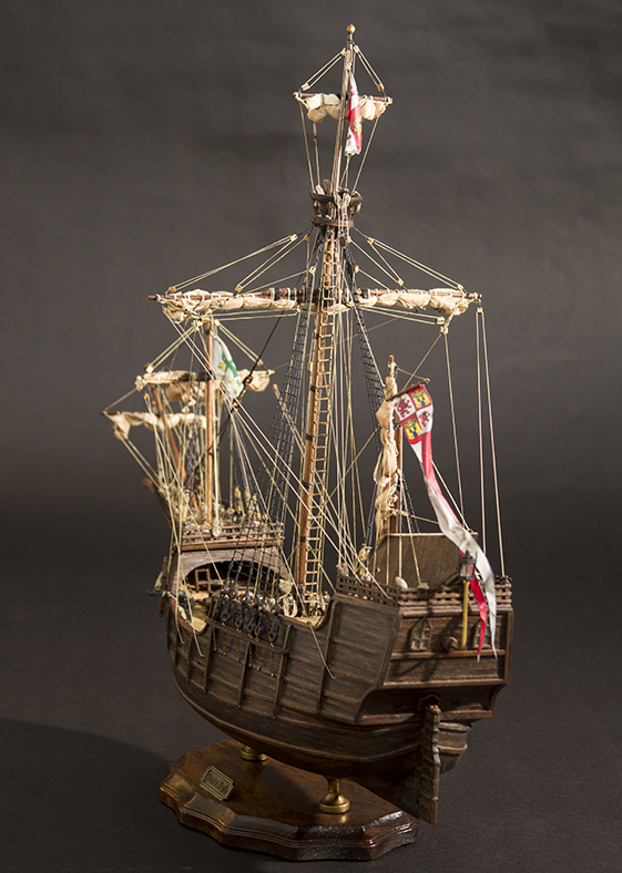
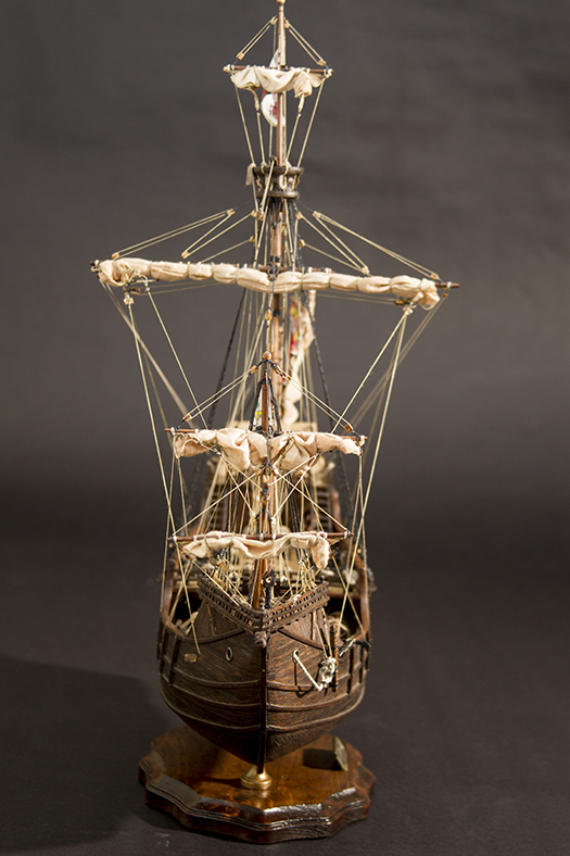
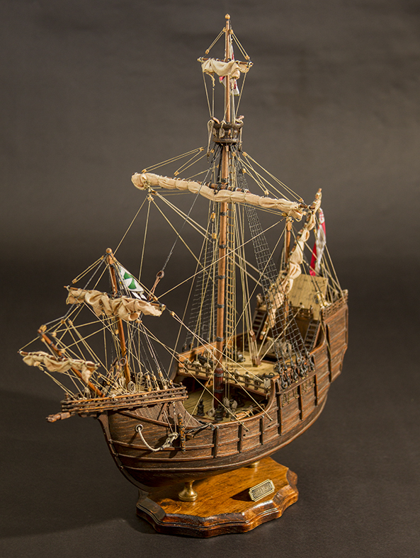
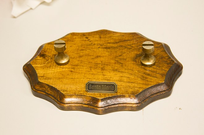
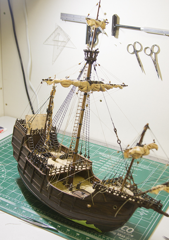
Most people know that the ship “Santa Maria” or La Santa María de la Inmaculada Concepción was the flagship of Christopher Columbus’ journey to the Americas. However, people may not realize that there is very little historical evidence regarding exactly what the “Santa Maria” looked like, or how it was built. There was little to no documentation regarding ship building in 1492, and this ship was scuttled and its lumber used for shelter not long after its initial voyage.
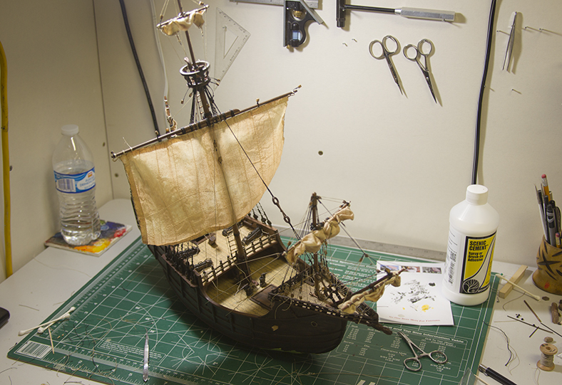
There is always a mixture of feelings nearing the end of a build. The sense of accomplishment is only slightly diminished by the sense of ending – and that you’re … well … finished.
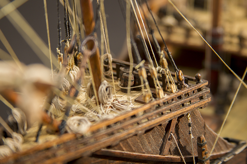
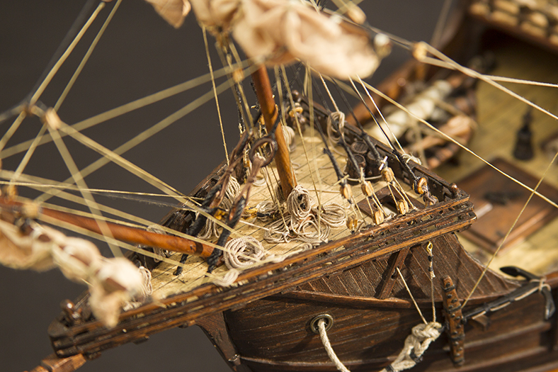
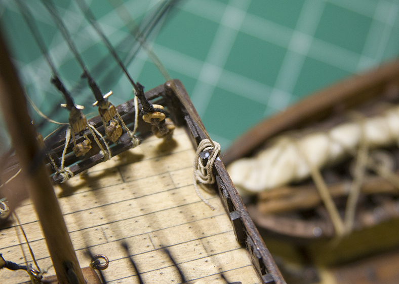
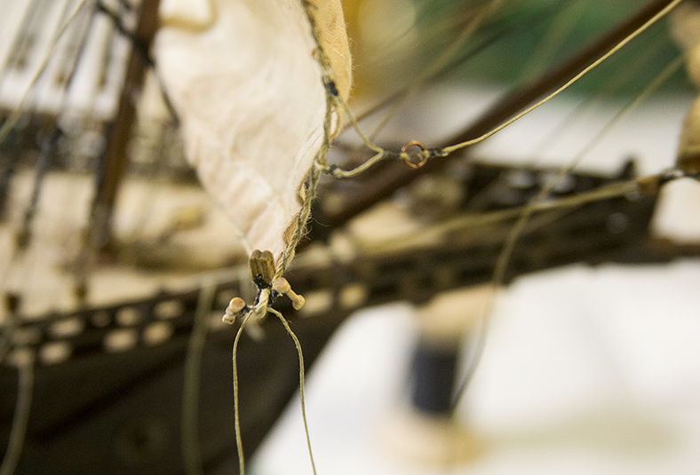
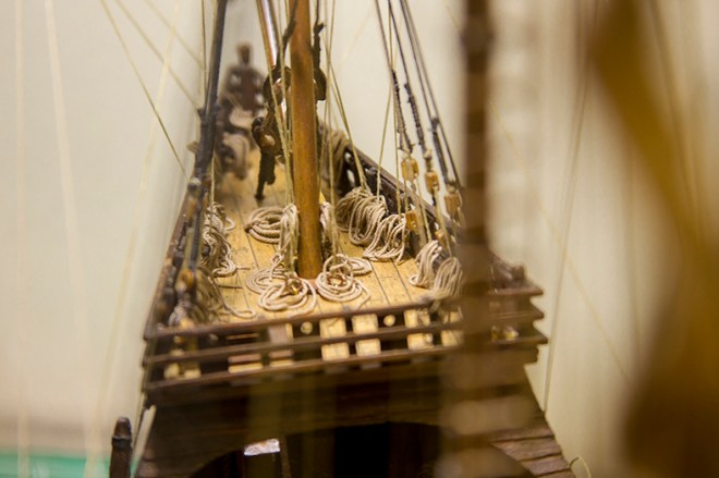
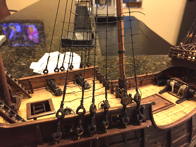
At any rate, as I near the end of the build I started working on some of the finishing details. A very important aspect (often overlooked) is the laying of coiled rope. A coiled rope will likely be found anywhere the running rigging terminates on the deck or a railing. Since this build already has a definitive “aged” look to it, I wanted to continue that process with the coiling of the ropes. So, I concentrated on making them “messy” to imitate the ‘orderly chaos’ that is often found on a ship underway.
An important aspect of coiling ropes is how to secure them in place while at the same time making them retain a naturally hanging look. The glue becomes very important – as many kinds of glue will discolor the ropes significantly.

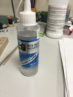
I settled on a very thin white glue that’s primarily used for building scenes on train sets. It dries clear, and takes a while to harden so you can manipulate the coil. The challenge is, holding the coil in place until it is tacky enough to stay.
For coils that typically just lie on the deck, I used a styrofoam glue that also dries clear, but is much more tacky – more like a rubber cement. It is very messy and stick, but worked well for coils that needed to be “bent” in specific ways.
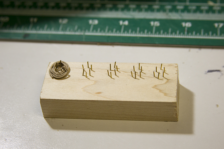

For the ropes coils themselves, I build a small jig to wrap and glue some of the coils that lay freely. However, most of the coils were wrapped individually around the rigging lines.
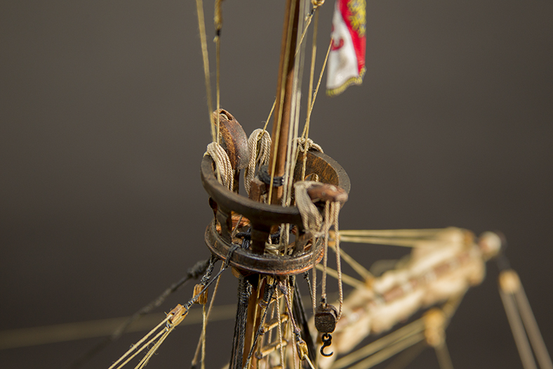
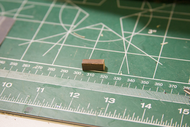
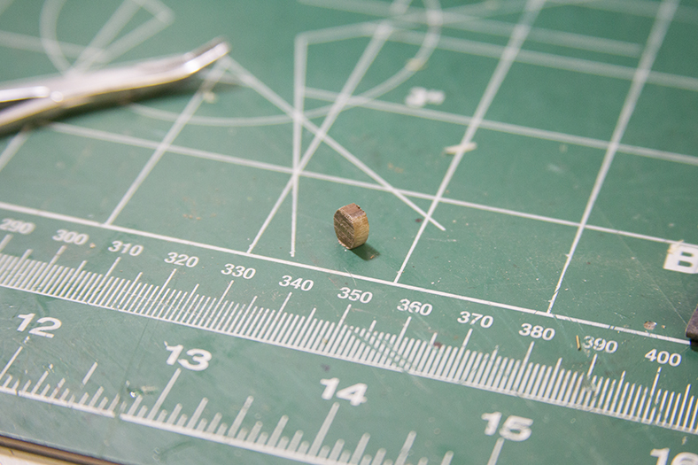
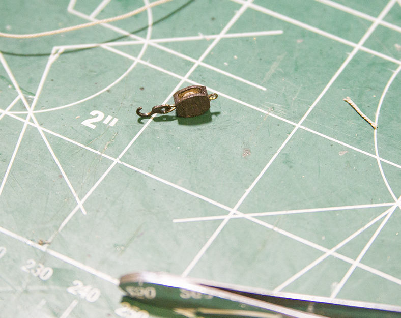
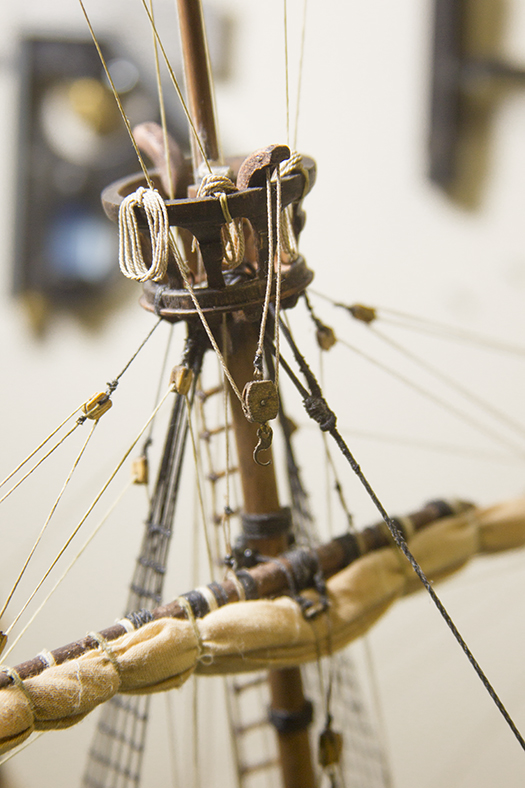
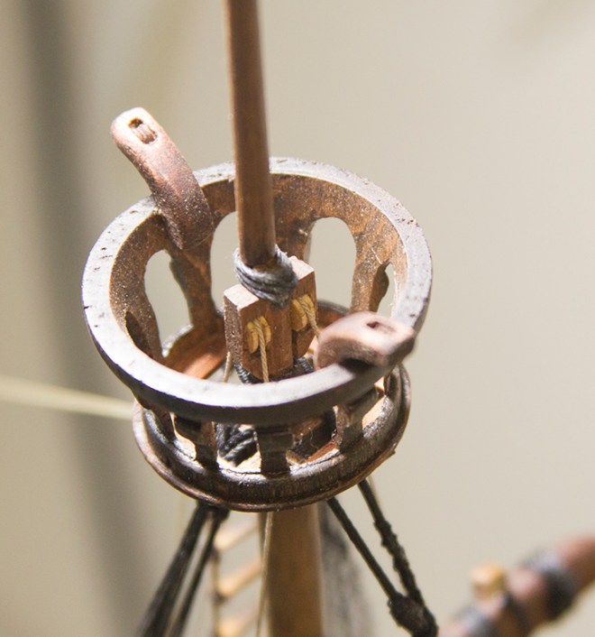
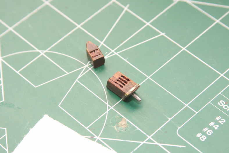
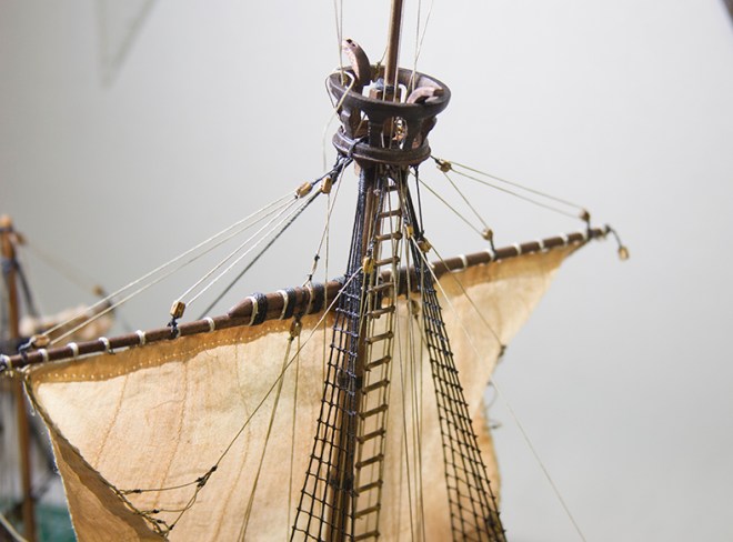
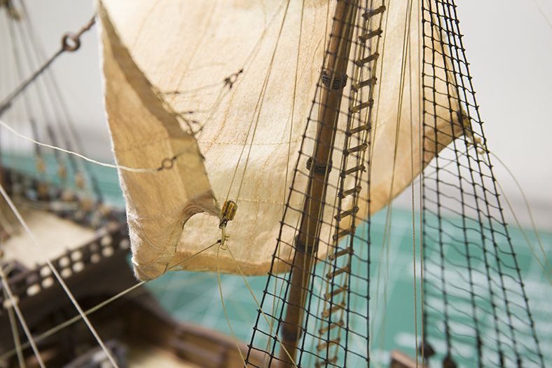
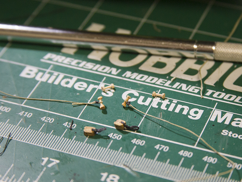
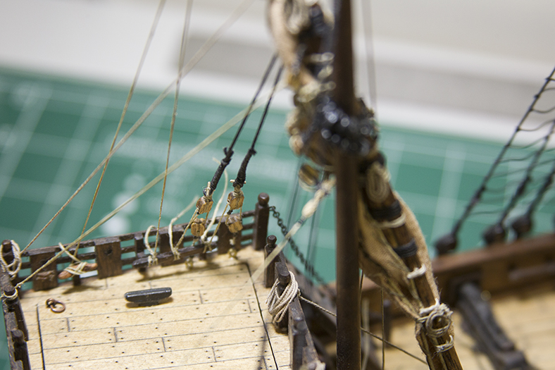
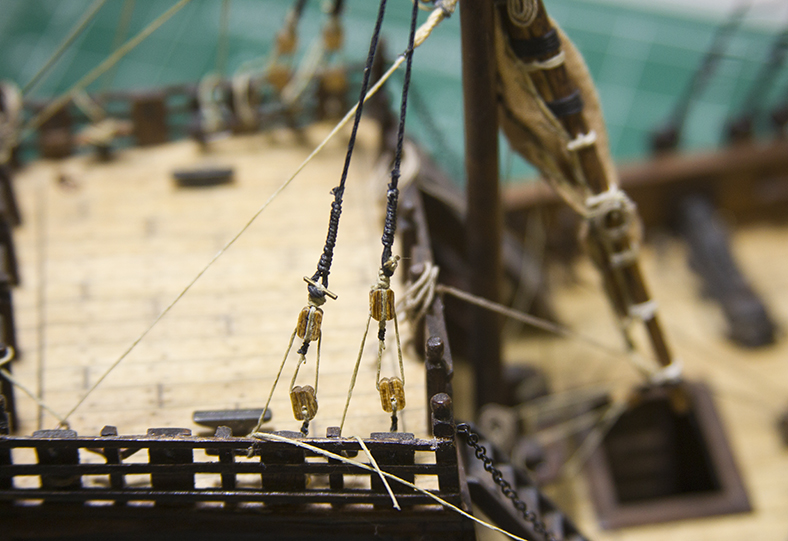
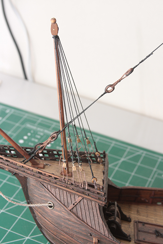
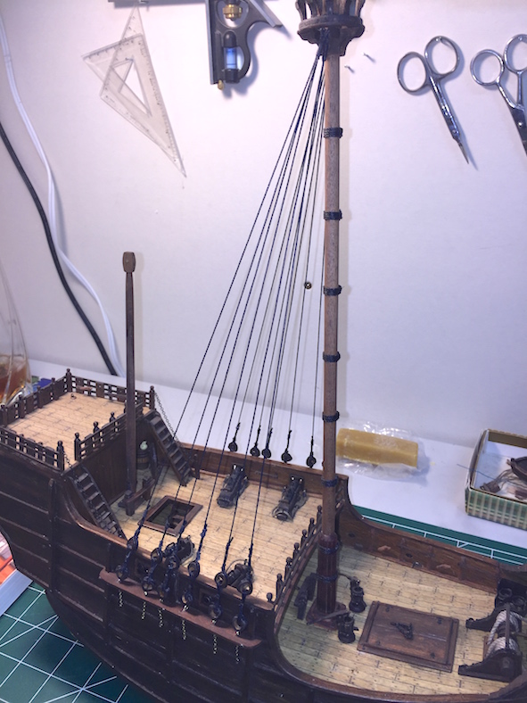
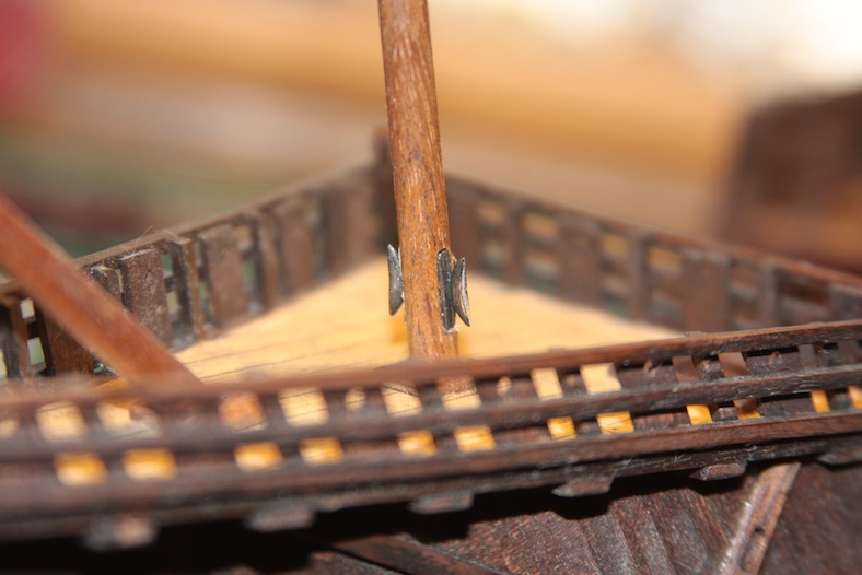
According to Xavier Pastor’s book, the two sheave pulleys that extend from the crow’s nest were used to move and/or load things onto the deck. To create them, I needed to build small pulleys from scratch. Similar to the sheaves on the top of the masts, I started with a 5mm block, rounded the edges and drilled out the center.
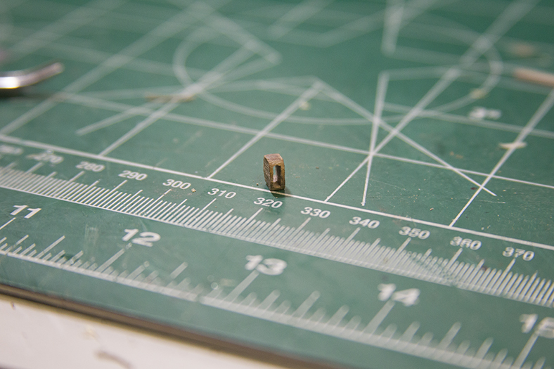
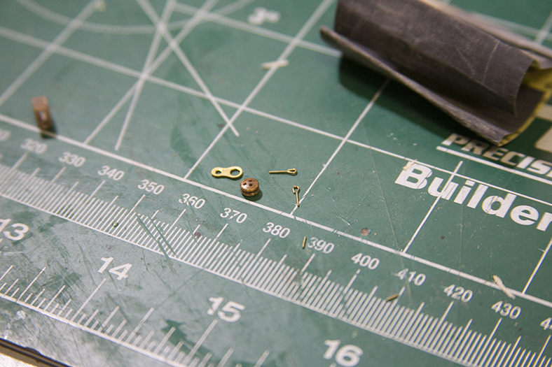
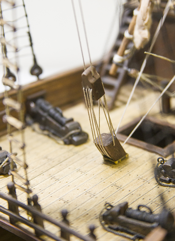
I then used some scrap pieces (a small deadeye, an old eyelet, and brass attachment) to create the rest of the pulley. I then rigged it through the sheave, coiled a rope, and left it hanging for the crew to use when needed
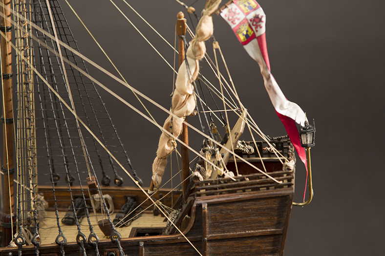
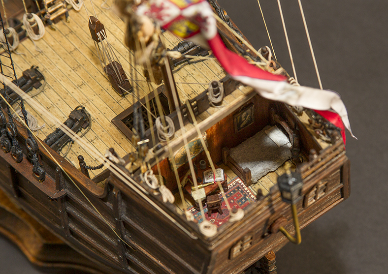
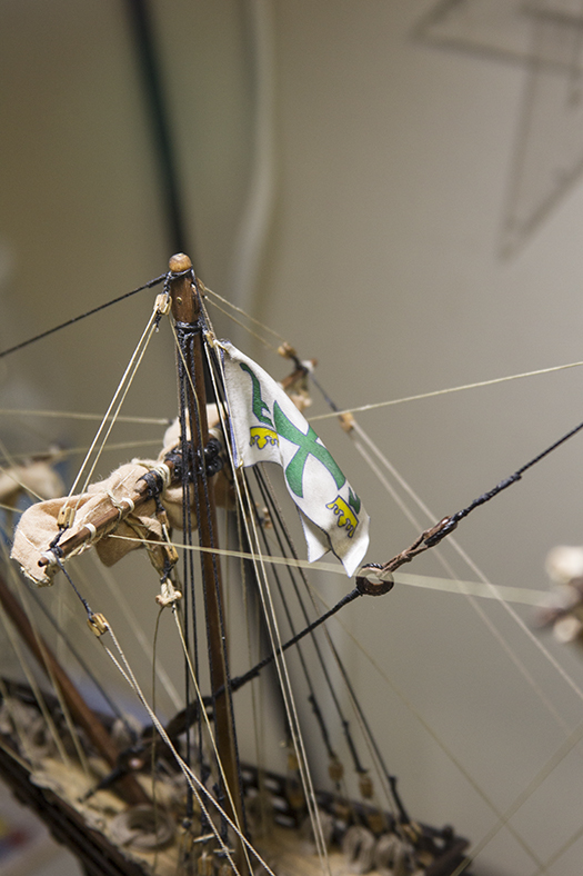
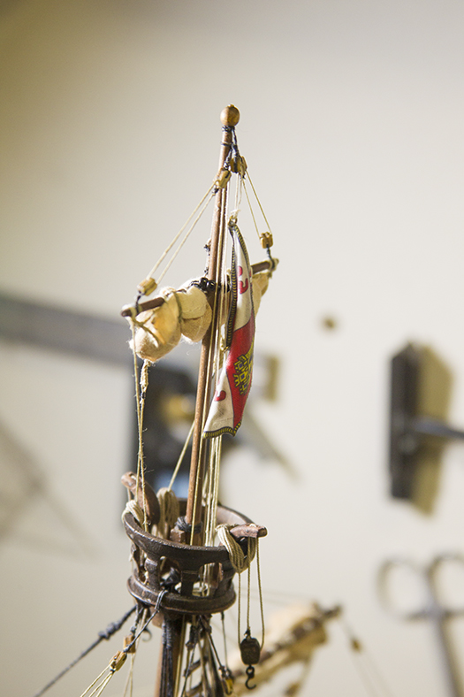
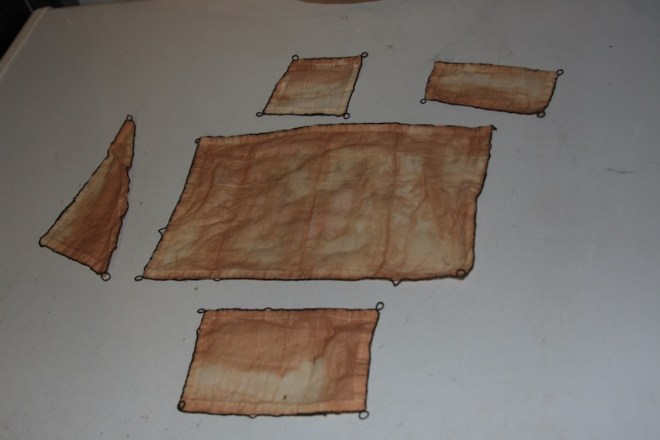
Next up were the flags. I’d been struggling with the concept on how to display them for a while. The key for me, was to create a method in which they hung as naturally as possible. I’ve seen many models where the ship was beautifully constructed, but the flags were sticking straight out in direct contrast to the rest of the ship.
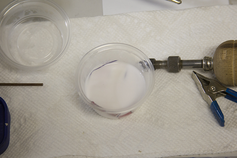
After experimenting with various fabrics from silks to satins, I finally settled back on the fabric “stickers” that were included in the kit. As it turns out – their colors were actually a great reflection of the flags illustrated in Pastor’s reference.
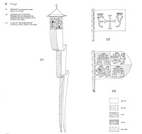
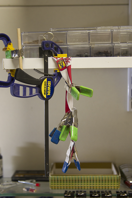
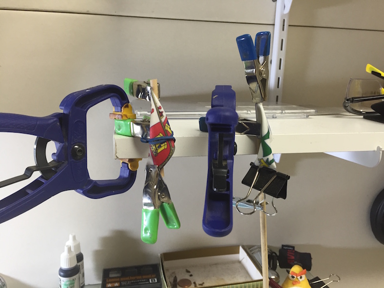
The trick then became how to make them seem less “stiff”. First, I soaked them all in the thin white scenic glue mentioned above. I then used various clamps and rubber bands to get an approximate shape of them ‘drooping’ or hanging with folds and let them dry.
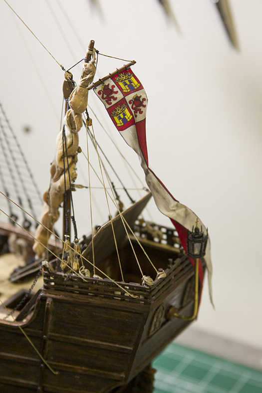
The resulting effect was pretty close to what I wanted. Finally, I aged the flags using a little bit of aging soot and ‘dirt’, and I was ultimately happy with the result. Each flag was then rigged with a small pulley. The longer banner was first attached to dowel as illustrated in the schematic, then mounted to the mizzen. I had to be careful to lay it in a way that still allowed the rear deck to be raised and lowered.
And… you know you’re getting close to the completion of a build, when this little detail is next up on the work desk…
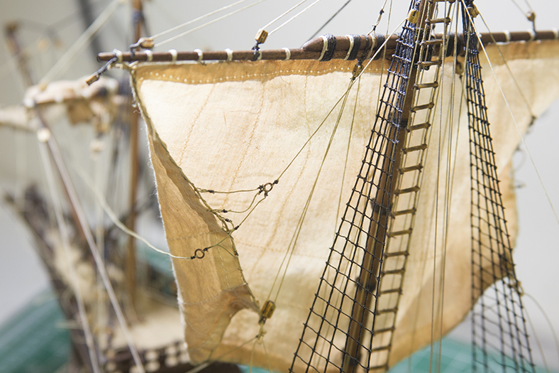
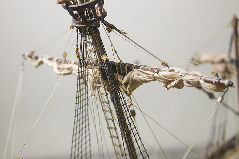
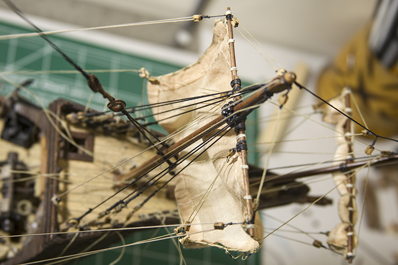
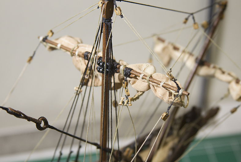
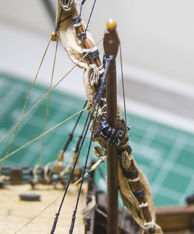
The main mast running rigging is usually the most complicated on the ship. Because the yard itself and the sail are both so large, the rigging needed to keep everything in place – particularly under heavy winds – is heavier and more intricate. However, the basics are the same as the other yards and sails.

The parrel is essentially the same as the other yard, with the exception of the size of the ribs and trucks. There are also three rows of ribs as opposed to two. As with the other parrels, they are attached to the yard in the front with a tackle that runs to the deck.


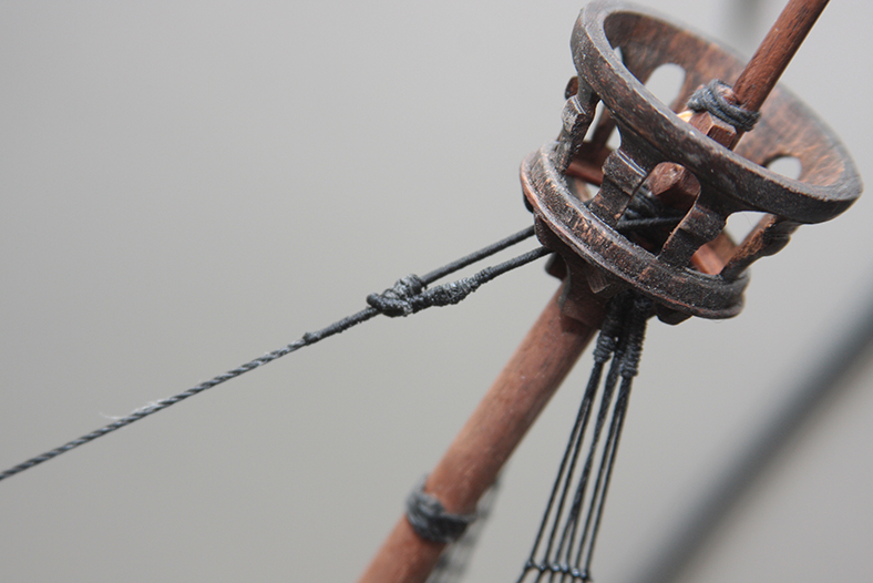
As the main yard is so much larger than the other yards, the method of raising and lowering it is much more complicated. The Halyard becomes a more intricate rig. The yard itself is held using two ropes called a “Tye” which runs up through a double sheave at the base of the topmast.
The tye then runs to a Knighthead” where the halyard is rigged. The knighthead assembly is made up of two pulleys called the “ramhead” at the top and a “knight” attached to the deck. A single halyard is wrapped through the pulleys several times to hold the main yard in place.

The force endured by the main yard and main mast would have been terrific depending on the level of winds propelling the ship. This complicated rigging would have lessened the force on the resulting ropes to make them much more manageable.
The yard itself was held up by “lifts” just as the other yards. However, the lifts for the main masts are essentially doubled through two sets of blocks instead of the on set. Once again, this split the resulting force and pressured put on the ropes and blocks.
The bridles on the main mast also needed to be doubled up. The two “bridles” were run toward the fore of the ship and rigged to the bowsprit. Three more lines called “martnets” were run upward along the aft of the sail to blocks attached to the crow’s nest.
The tacks (running to the fore) and the sheets (running to the aft) were attached to the cringles (corner of the sail) using toggles. There is some contradiction in Pastor’s book whether they were attached using blocks or toggles – but as I liked the look of the toggles and wanted to remain consistent, I went with them.
The block attached to the cringle runs the clewgarnet up to the assembly under the crow’s nest, then down to the deck fittings.
After the main sail was rigged in place down, it actually was quite difficult for me to decide to furl it. It looked very appealing down. However – were I to leave it down, it would have also required resewing the sail – as I did not attach a lower bonnet (which would have been included in a fully lowered mainsail).
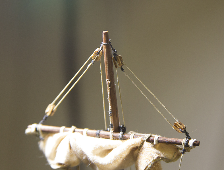
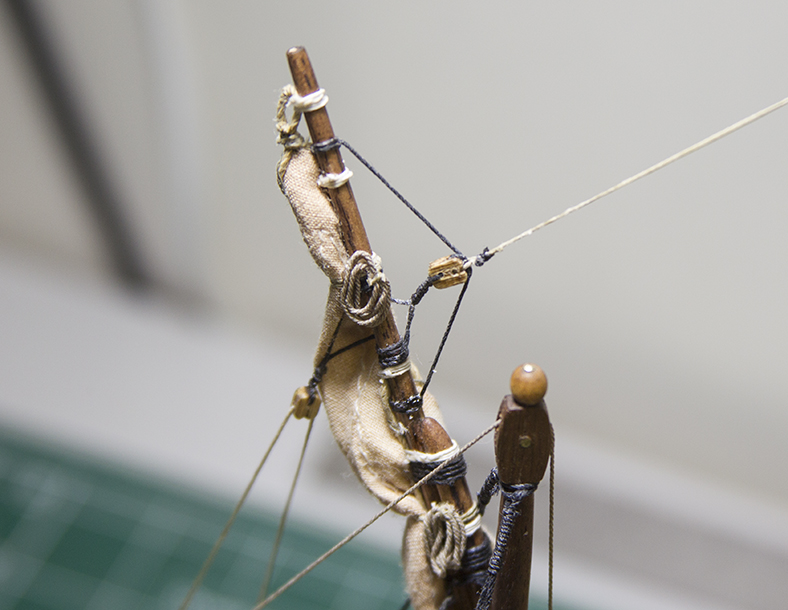
I decided to wait until after I rigged the topsail before making my final decision. The topsail (the yard and sail above the crow’s nest) is the easiest and least complicated to rig. The parrel is a basic strip attached to the yard, then run through a sheave in the mast itself. The sheave is created by VERY carefully drilling out the mast, then cutting off a thin dowel.


The rig goes through the sheave then runs down through the crow’s nest to the decking. Only two lifts attach the yard to the top of the mast with blocks, then run to eyelets inside the crow’s nest.
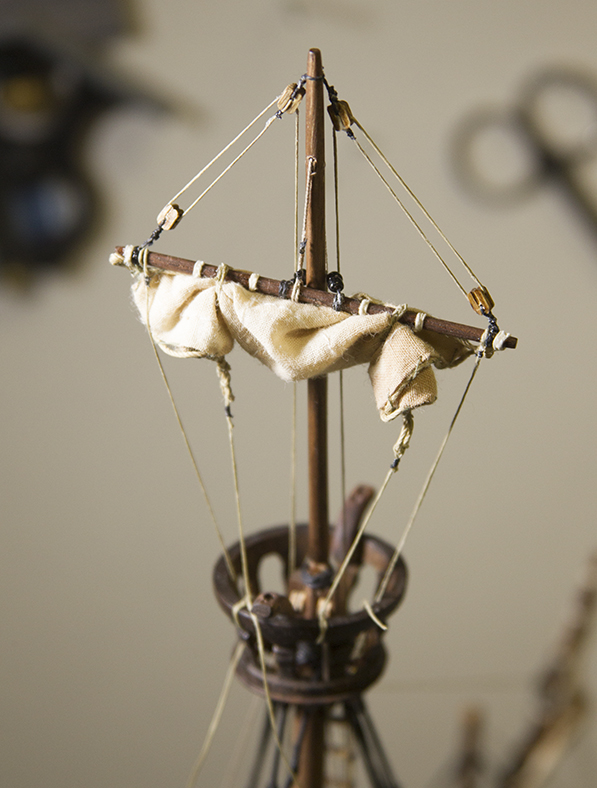
After rigging the topsail, and being able to adequately compare the look of the main sail down and furled, I decided to stick with my original plan. This was also influenced by the opinion of my lovely wife who also preferred the look of the ship with the sails furled.
So, I re-rigged the main mast and furled the sail.
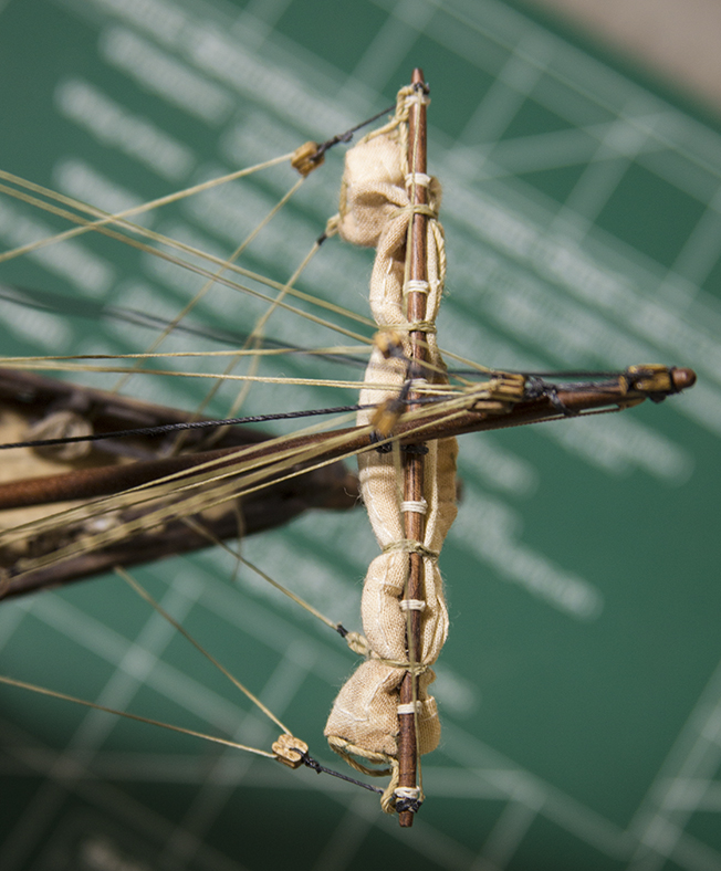
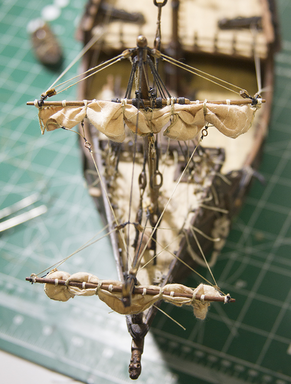
The Foremast is the front mast of the ship located on the foredeck. Once again, the yard itself is attached to the foremast using a parrel made up of trucks (small round balls) and ribs (larger spacers). The Parrel is tightened and loosened with the parrel rope rigged to a tacked and the halyard. The Halyard runs up the mast first, through a sheave pulley at the top of the mast, then down the rear of the mast and attached to a deck railing.
The yard is held in place and adjusted with rigging called “lifts” that run from the yard arms to the mast (attached with blocks) then down to the deck of the ship. The sail is attached to the yard with “robands” – simple strips of rope. The sails are then held in place and manipulated with a series of running rigging attached to the sides and the corners of the sails. The sides of the sails are attached with “bridles” and adjusted using a “bowline.”
The corners of the sails are called “cringles” and are held in place and adjusted using “tacks” and “sheets” hooked into the cringle using “toggles” or small dowels. A small block is then run up to the top of the sail with a “clewgarnet” – a rope using to raise and lower the corner of the sail.
All of the rigging is then tightened and run to various blocks and rails laid out on the foredeck. Once the sails are raised, they are then furled and attached to the yard.
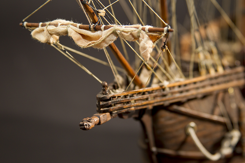
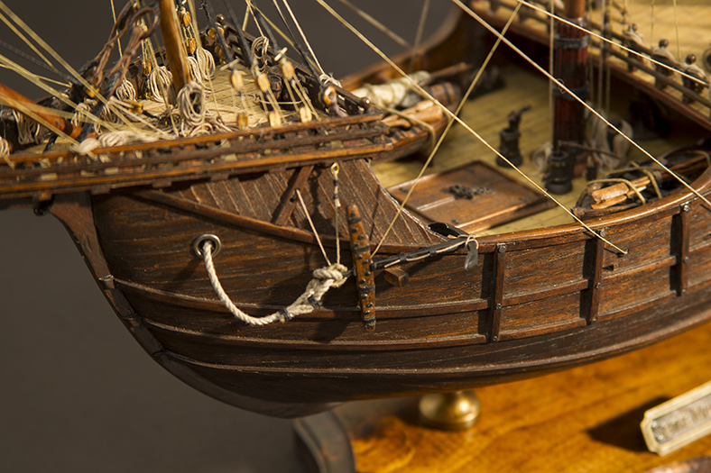
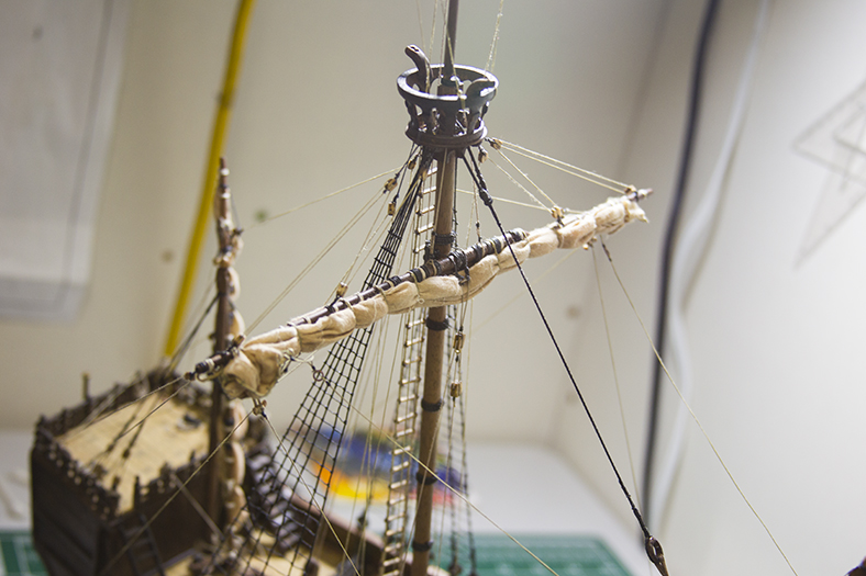
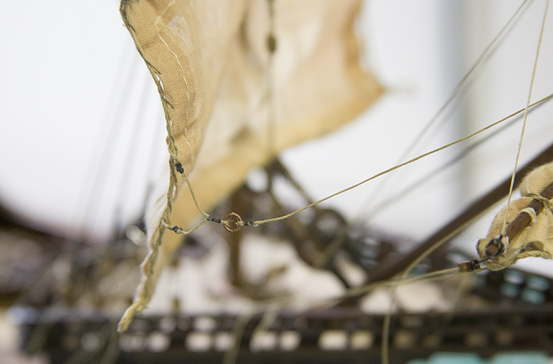
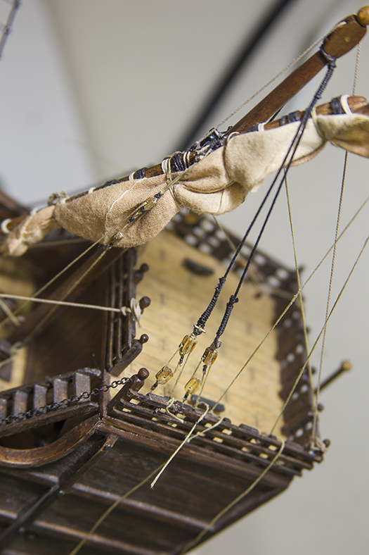
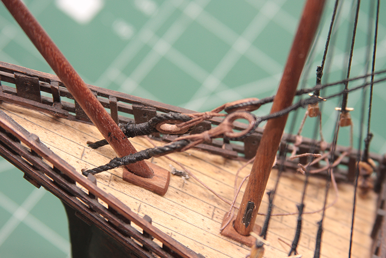
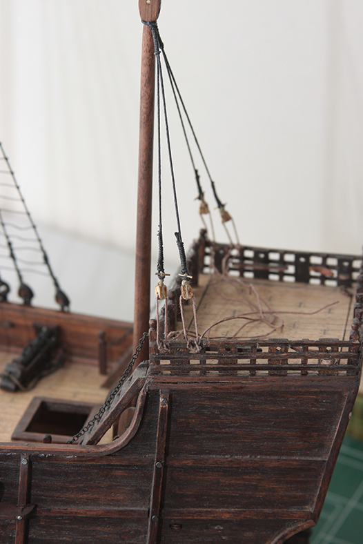
The spritsail assembly is the small mast and yard that stick out the front of the ship. It is rigged similarly to the other yards and masts, with a couple of additional elements that allow it to be specifically manipulated to catch wind.
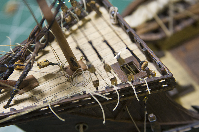
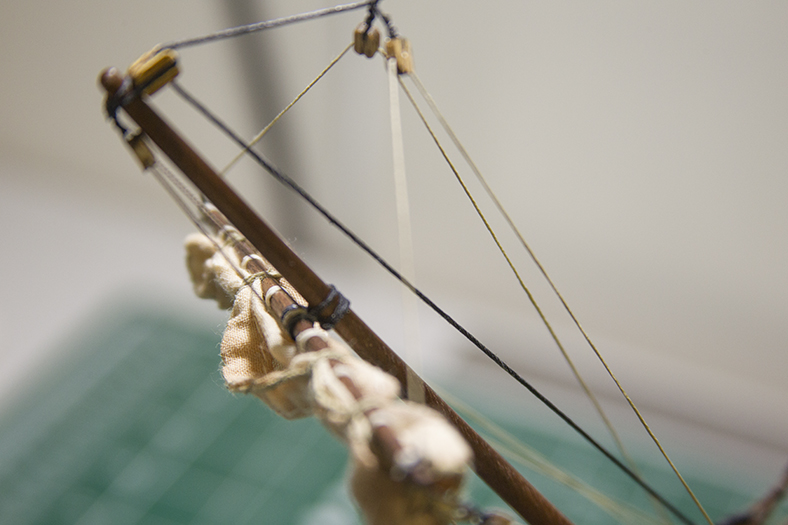
The lifts are attached by blocks to the Mainstay, then run to the foredeck and coiled. Since a lot of the running rigging, not only from the spritsail – but also the foremast and even mainmast, is attached through the bowsprit to the foredeck, it becomes a spiderweb of carefully orchestrated rigging. When trying to rig with accuracy, it’s vital to keep an eye on all the lines to ensure that they don’t physically overlap and always remain functional.
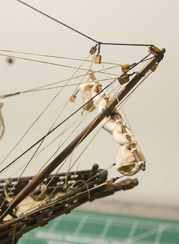
With all that rigging culminating in one relatively small location, the resulting “spaghetti” that ends up on the deck is chaotic at best. I’ve chosen to coil the ends of the rigging in a little more haphazard manner, hopefully giving her an “underway” look.
The running rigging on a ship consists of ropes, pullings and blocks that sailors use to raise and lower the sails, as well as adjust the yards – the crossbeams attached to masts that hold the sails.
Running the rigging is one of the most tedious yet fun aspects of a model for me. It represents a turning point in the process when you are closer to the end of the build than the beginning. Although there are certain “rules” with regard to running the rigging, there really isn’t a specific order. Regardless of which masts or sails you start with, there’s always a lot of running lines through and around one another.
Prior to starting the running rigging, I stained the sails to give them an aged look. To achieve this look, I soaked them in tea over night.
It’s also important to note that this is the first build where I’ve chosen to rig the sails “furled” – wrapped up onto the yard and unused. I felt that the only way to achieve the proper and accurate look of this was to rig them down, then actually use the rigging to raise them and furl them afterward. I think that gives me a good idea of how they would have appeared when raised by sailors while underway.
I followed Xavier Pastor’s rigging models, along with my aforementioned schematic to cleats and rails. I decided to start with the mizzen mast. Since I have a poop deck that raises and lowers, I had to come up with ways to run the rigging in a traditional manner, while incorporating the very NON-traditional aspect of having a deck actually move out the way!
The yard is attached to the mast using a “parrel.” The Parrel is essentially cylindrical objects strung around the mast with guides in between. The parrel lets the yard “roll” up and down the mast when the rigging is pulled.

The parrel is attached to the yard in the front using two blocks rigged together to form a pulley. The pulley is controlled by the “halyard” line, which actually raises and lowers the yard. The Parrel itself is wrapped around the yard and looped together. This process either looses or tightens the parrel as the yard is raised and/or lowered.
The top of the mizzen yard is attached to the main mast with a rig called the “lift”. The bottom is attached to the the deck of the ship at a couple of different points with “tacks” – in my case it is attached the rear rail. The mizzen is unique because of the angle in which it is attached to the mast, as well as how it’s used. It is essentially part of the ship’s “steering system” and aids the ship when guiding the wind.
The rear shrouds (the standing rigging which hold the mast to the ship) are attached to the deck with eyelets. This became rather challenging when it came to keeping them far enough out of the way to allow the poop deck to be raised and lowered.
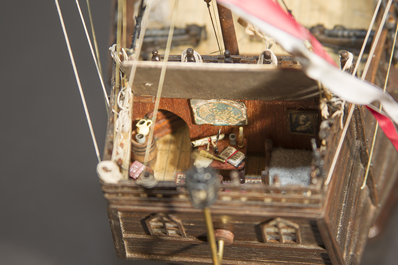
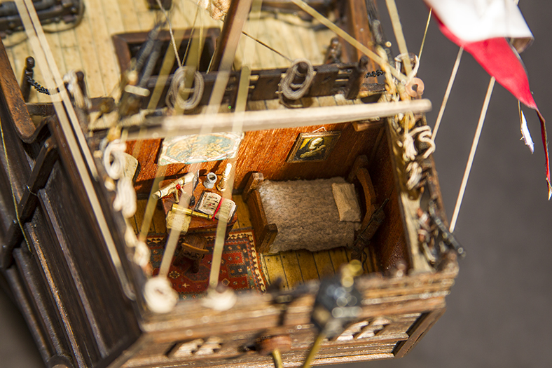
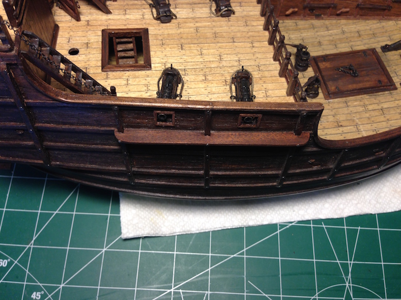
I am of course trying my best to maintain a very high level of accuracy regarding this Santa Maria build. However, at the same time I have taken the opportunity to embellish a bit – as I did with the Captain’s Cabin.
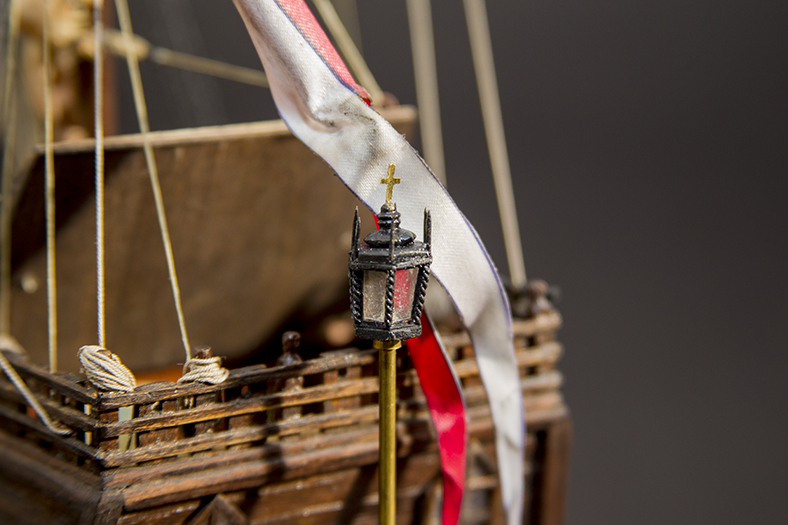
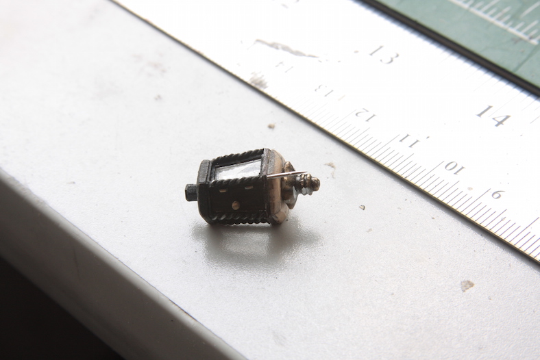
I decided that the stern lantern on the Santa Maria was another opportunity for me to get a little more elaborate than was likely actually on the ship. I started by having Chuck Passaro send me one of his Stern Lantern Kits so I wouldn’t have to manufacture the little bits on my own. Then I stained and prepped the pieces.
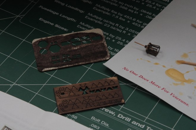
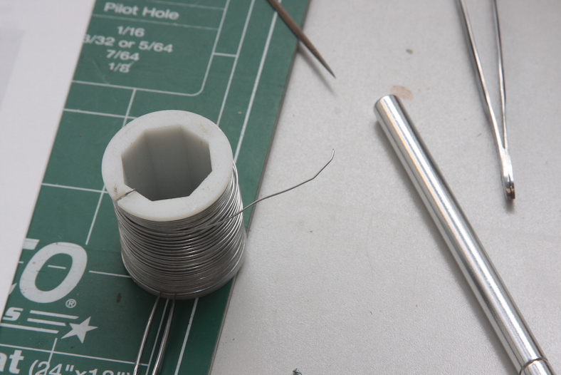
I put the basic pieces together following Chuck’s directions, then started the modification process. I based my idea on some of the Russian ship builder’s I’ve seen who are fantastic and creating miniature pieces. I used thin wire and wrapped two pieces together to create a “roped” look for columns. I then filed down and flattened one side so it’s easier to glue them to the corners of the lantern.
I pinned and rubbed the lantern black and used parts of brass nails to create the door handle and simulated hinges. I then chopped off the ends of straight pins and mounted them on the top of the lamp to create pointed “spires” that extend above the lamp.
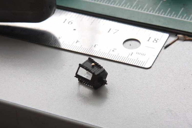
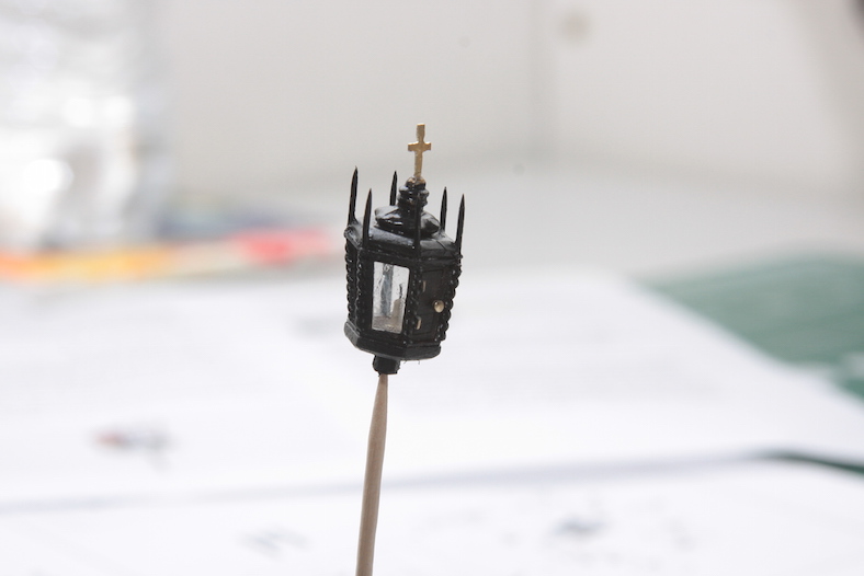
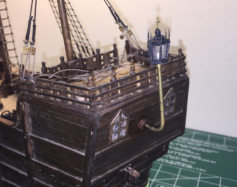
Finally, I took a 3mm wide brass strip and filed it to create a cross for the top of the lamp. I mounted the lantern using a brass dowel and finished the mount to the ship itself with a walnut base.
I’m getting pretty close to starting the running rigging on the Santa Maria. Which means, most of the deck fixtures have to be in places, or at least ready to go. This makes running the rigging much, much easier.
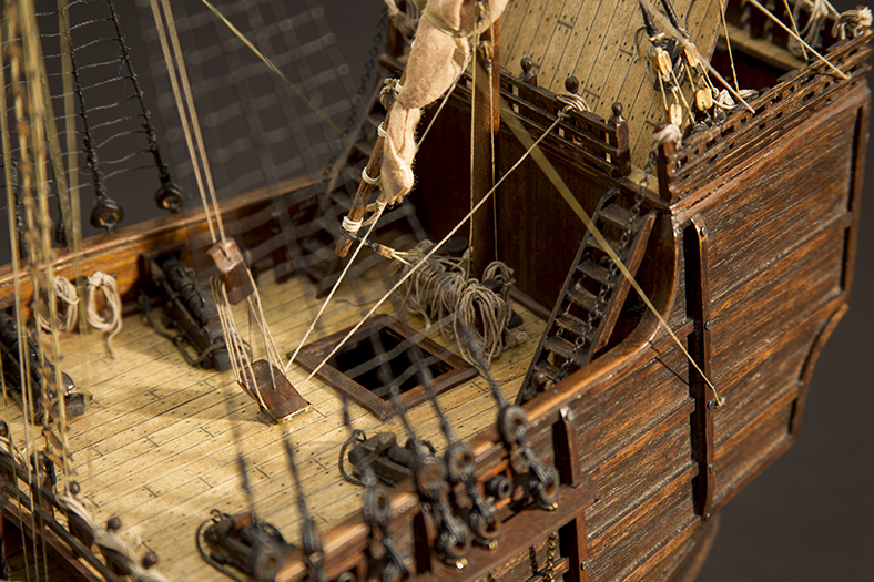
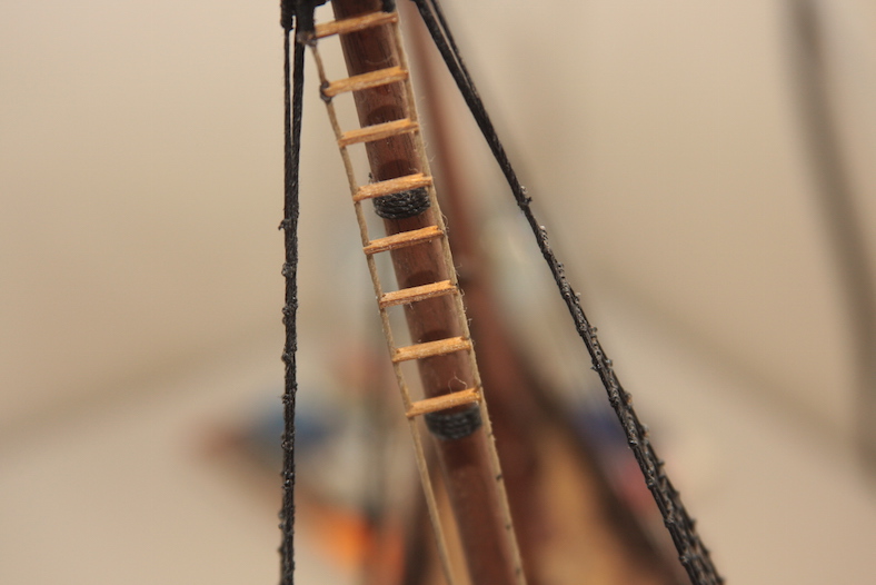
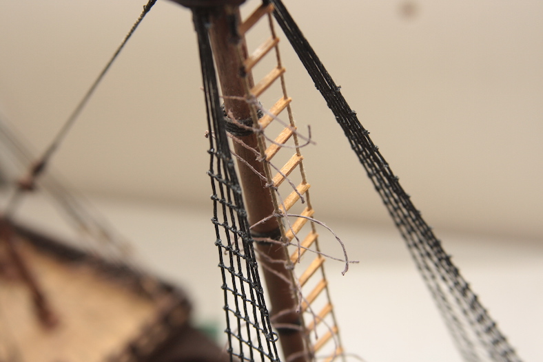
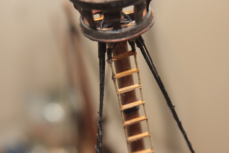
Although this was actually unbeknownst to me, apparently Naos of the time often included a rope ladder running the length of the mainmast. Like most folks, I just assumed sailors ran up and down the ratlines as often depicted in moves, etc. However, since this rope ladder was well documented in several places (including Pastor’s reference), I went ahead and put one together.
A pretty straightforward element, sides of the ladder were tied off to the mast and deck using typical techniques of wrapping and tying the ends. The steps were cut from 2mm strips then notched on the ends. They were tied to the ropes using what are essential clove hitch knots.
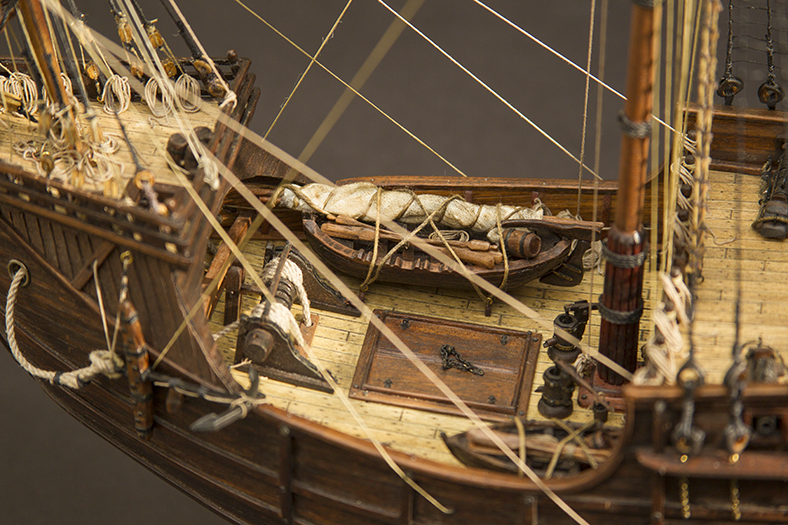
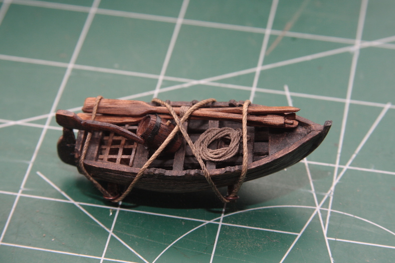
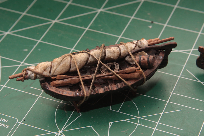
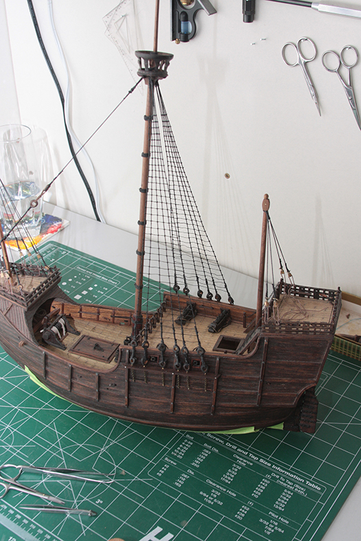
I wanted to finish off and mount the launches on the deck. They’re pretty large pieces, so I wanted them in place before before get too far along on the rigging – as trying to mount them around the running rigging sounded a little difficult to me.
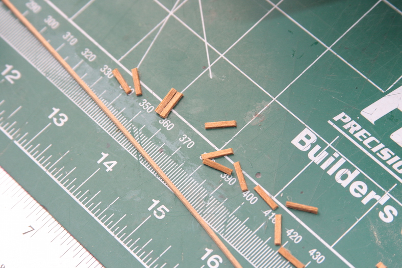
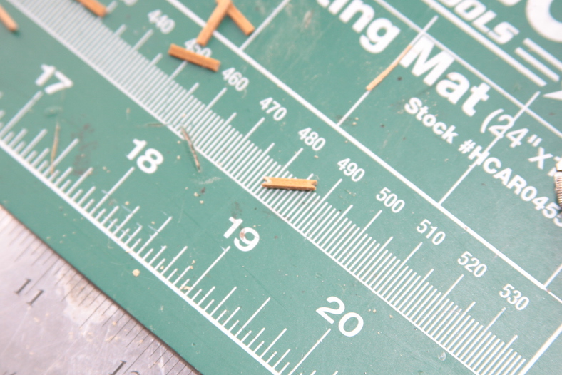
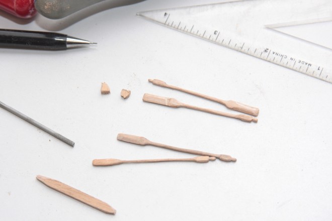
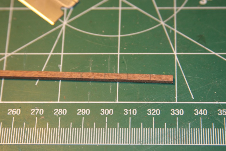
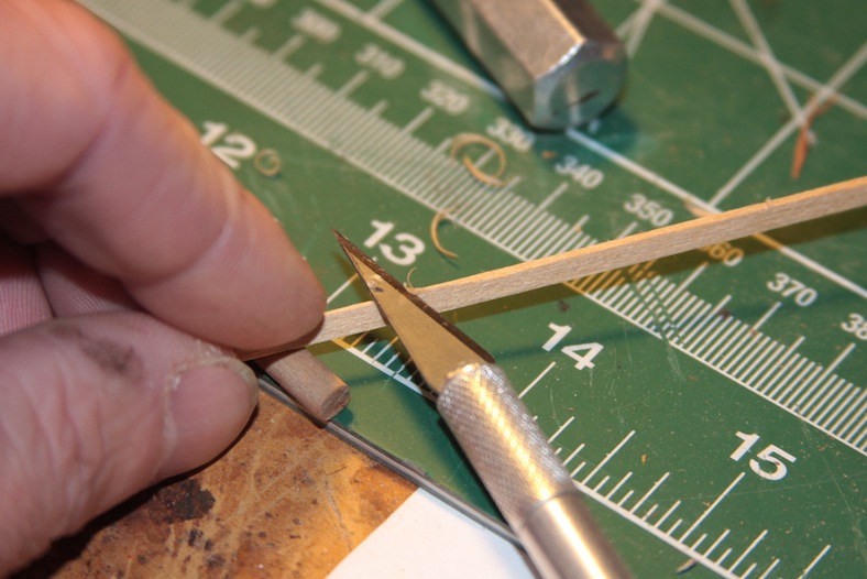
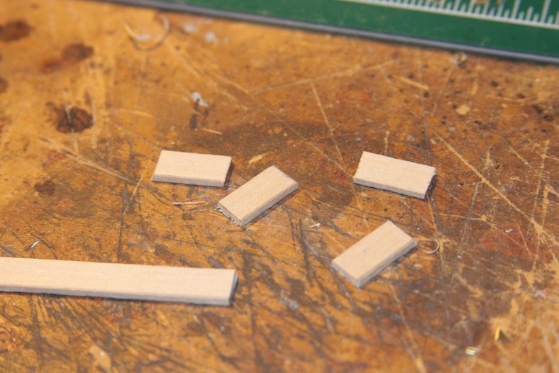
Finishing the launches meant carving out some oars. Also pretty straightforward, I created an assembly line of 5mm x 1mm strips, shaved off the edges using a mini belt sander, then sanded the oars down. These are the rough cuts prior to the detail sanding and staining.

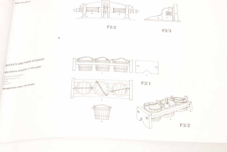
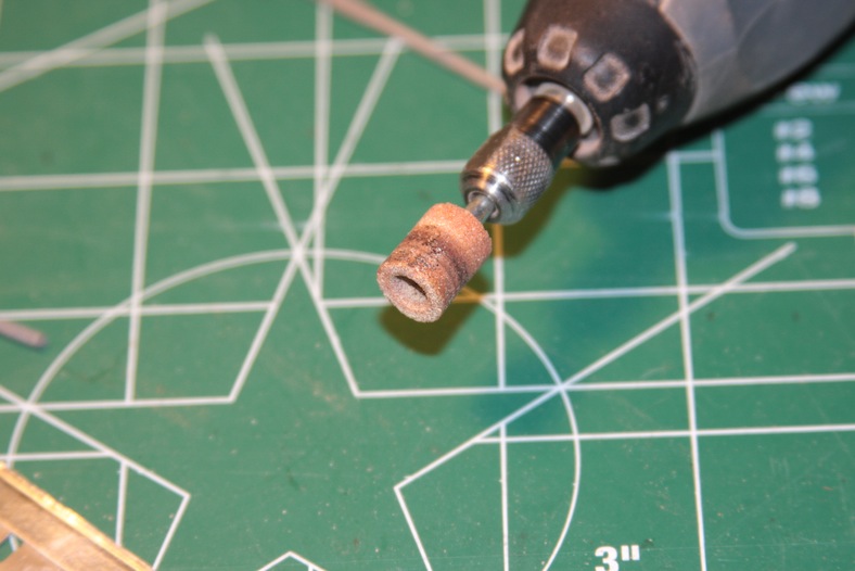
Similarly, I created a little assembly line for the buckets and barrels. The buckets are trimmed from 5mm diameter dowel pieces that are leftover scrap. The ends are sanded down and slightly tapered, then sliced down the sides with an X-acto knife to simulate “strips” of wood.
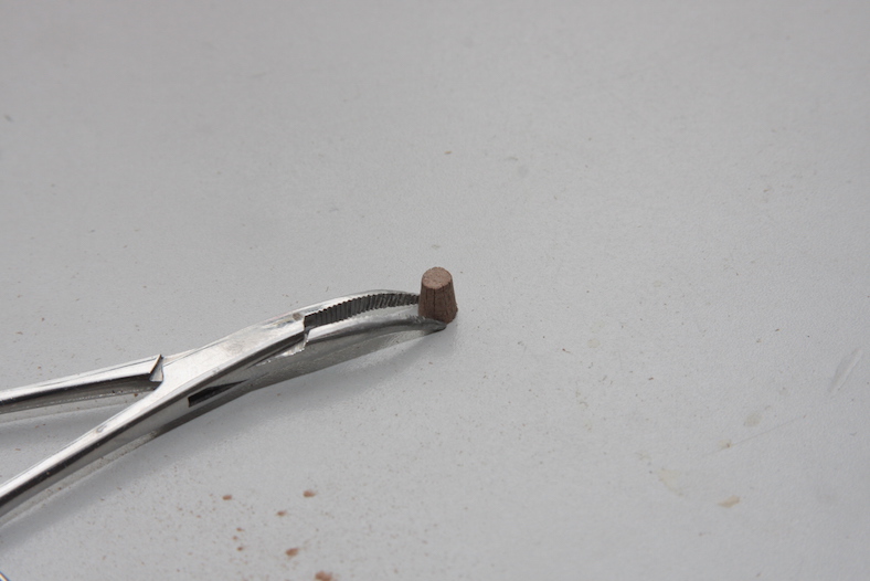
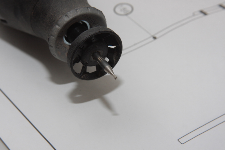
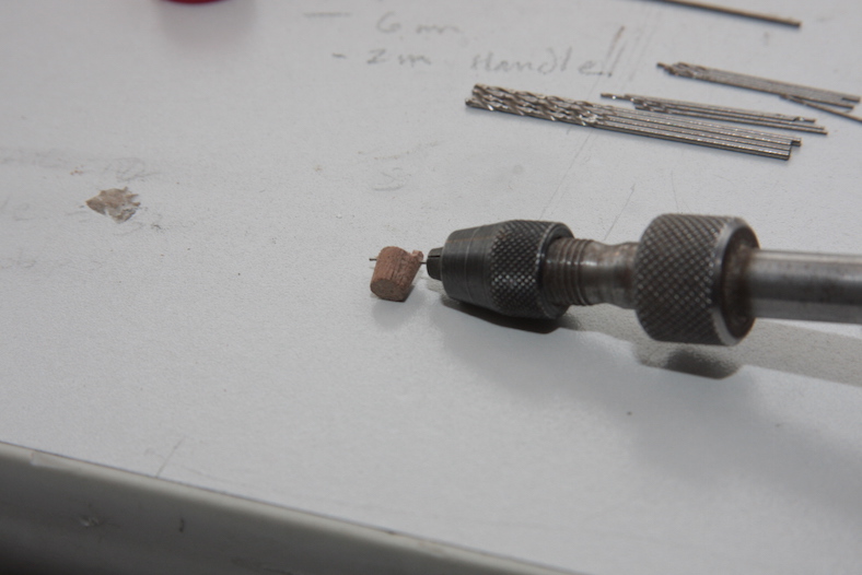
A miniature attachment for the dremel hollows out the bucket, then they are sanded down leaving to little “flaps” on the sides where the rope handles are fed through and tied off.
The barrels are very similar. Trimmed off of 8mm dowel scrap pieces, they are tapered on each end. The tops and bottoms are very slightly hollowed out using the same dremel bit as above, then sliced with the X-acto knife. The metal wraps are actually electrician tape – which is a great thickness, and also pretty easy to manipulate. It’s a technique I was happy with when I created the San Juan.
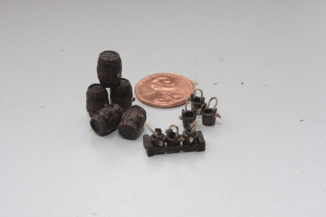
The little pieces are all dumped into the launches and tied off. I also threw in a couple coils of rope. The larger launch contains it’s own small mast and sail. This is just a scrap of material wrapped and tied to a 3mm dowel.
The mainstay is a strong line of the standing rigging that holds the mainmast forward. Were it not for the mainstay, the ship could easily be dismasted by the sway of the mainmast. The mainstay rigging has (like most rigging) evolved over the centuries. For the Santa Maria, I chose to use “Historic Ship Models” by Wolfram ZuMondfeld as a reference for the time frame. I also referenced some other models of the Santa Maria from other builders.

Step one was to create open blocks to remain consistent with the ratlines, etc. I used a 12mm dowel, cut off the ends and drilled them out.

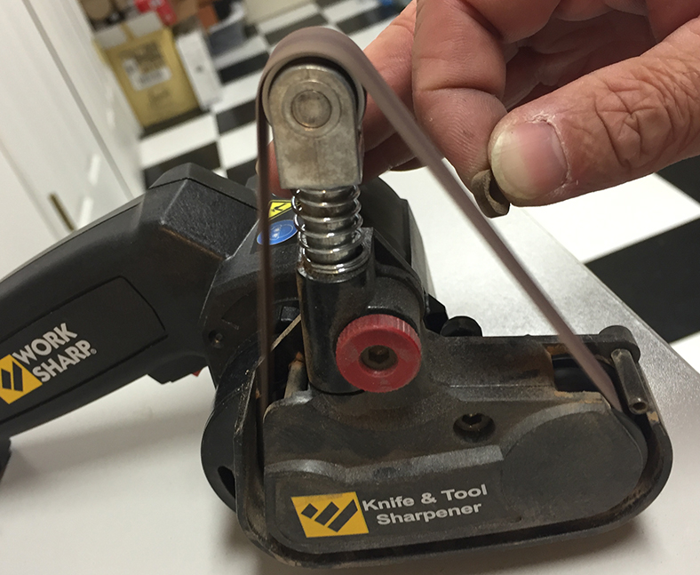
I rounded and sanded them using this handy little tool that my mother bought me as a housewarming gift. It’s actually a knife / tool sharpener, that comes with a variety of different sanding belts. When you take the knife adapter off, it makes for a great miniature belt sander.


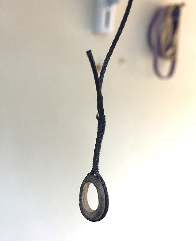
The top of the stay that loops around the top of the main mast is a reinforced wrapped rope. This is also the method of securing the rope to the blocks. So I simulated the effect by taking small diameter rope and wrapping the large diameter rope and creating the knot.
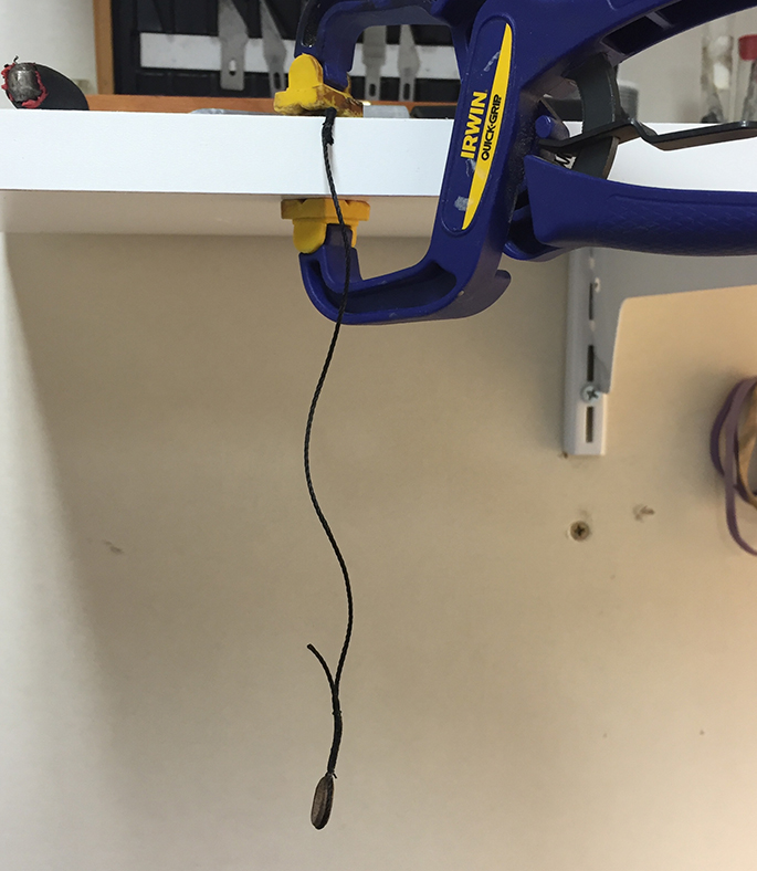

My method for accomplishing this was to clip the top of the stay to a shelf, and the bottom of the stay to my desk. This kept consistent tension on the stay allowing me to wrap the smaller thread around the larger rope without it twisting too much.
The upper half of the mainstay is connected to the bow of the ship through the foredeck. It’s always sketchy when it comes time to drill holes in the deck as mistakes are unforgiving. The rope runs through the deck, around the bow keel, then back up through the deck. The ends are attached to to blocks. The blocks are combined around the foremast then connected to the upper half of the mainstay with another set of blocks.
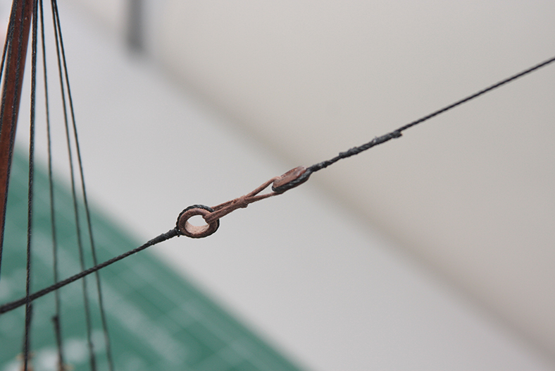
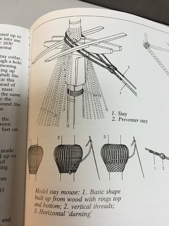
The upper end of the mainstay is wrapped around the mainmast, through the crow’s nest, and reconnected using a loop and a “mouse” – essentially a woven knot. Clearly wrapping and weaving the knot as illustrated was too detailed for a small scale, so I simulated the mouse knot with a basic wrap.
I followed up the mainstay with the fore stays and the aft stays. This are more simplified stays with basic single blocks. I added a small rod in the stay as a functional addition which seems to have appeared on some but not all ships of the time.
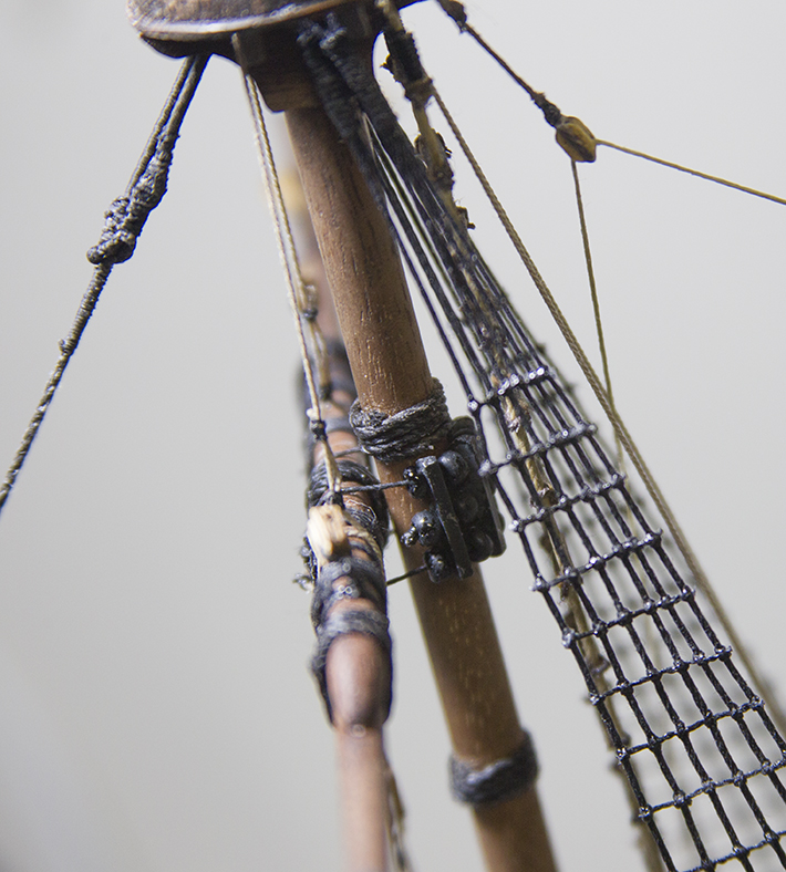
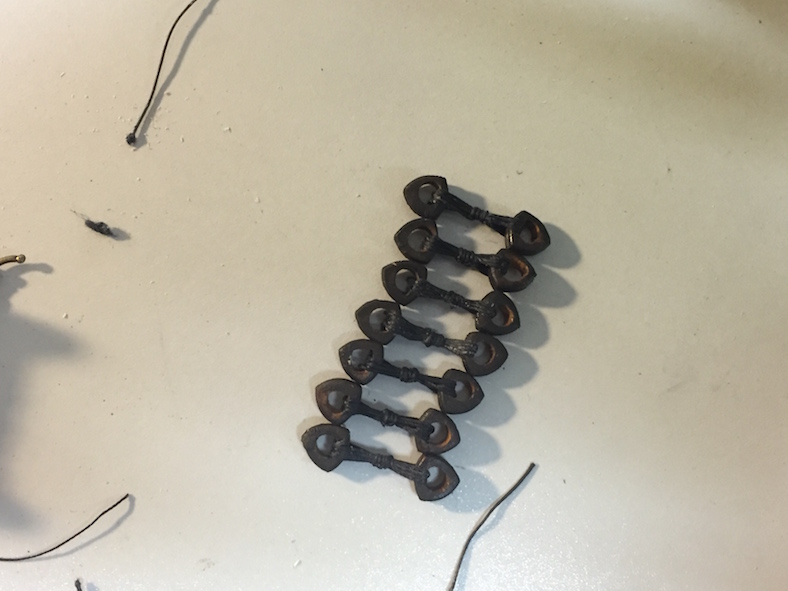
The purpose of the shrouds is to provide masts with lateral support. As a relatively small ship, the Santa Maria most likely had six pair of shrouds on the main masts that were then secured to the channels using deadeye blocks. The shrouds and ratlines are often the most recognizable and visible part of a ship and model. Throughout history the image of sailors or pilots climbing up and down ratlines are forever immortalized in movies and our imaginations.
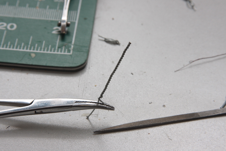
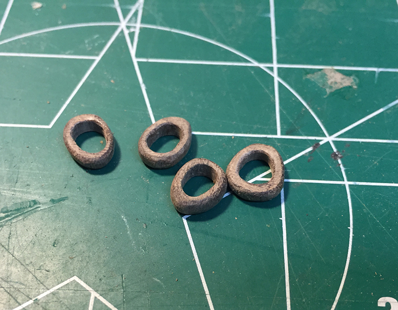
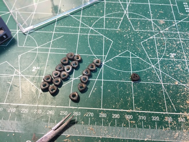
There is some question as to the type of deadeye blocks that are used on the Santa Maria or other ships of the time. Once again, some subjective judgement is necessary in this area. While it appears to be clear (from a Flemish carrack 1480 model and others) that earlier deadeyes were triangular or ‘pear shaped’ it is not clear at which point deadeyes moved from being an open hole, to the three holes that become the norm. Based on the premise that the Santa Maria was an older, existing ship that was purchased, and some input from Xavier Pastor’s research, I decided to go with an open hole version.
So, step one was to drill out the triangular deadeyes and open them up. Always a delicate process, I held the deadeyes steady with suture clamps, then drilled them out with a dremel. Any drilling is always followed up with some soft sanding.
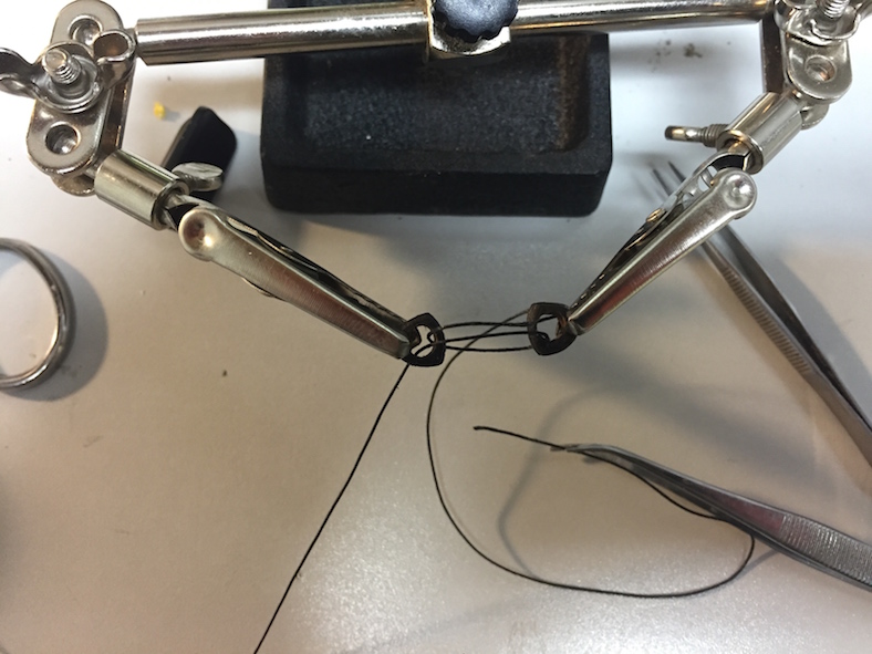
Step two is to rig the deadeyes. I used my handy soldering clamp to keep the distance between the deadeyes consistent. The process is a bit dodgy, since each time you tighten the ropes, the deadeyes have a tendency to squeeze together closer regardless of how tight the clamps are. This is less likely in the newer, three holed deadeyes.
Once the deadeyes themselves are rigged, they are attached to the channels. First, holes are drilled in the channels, eyes inserted, then those eyes are attached to the wales of the hull. The amount of tension on the shrouds or backstays was tremendous, so it was important for them to ultimately attach to the strongest part of the hull.
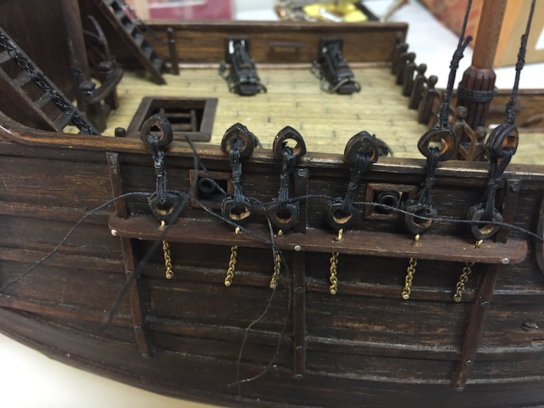
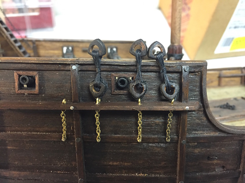
The deadeyes are then attached to the eyes. Once again, it’s important to wrap and tie them evenly so the lengths of the deadeyes and shrouds remain consistent. The shrouds themselves are wrapped around the main mast through the crow’s nest and ganged together in pairs. After wrapping around the mast, an eye is seized in to them middle of the rope. The eyes are looped over the mast alternately so that both part and starboard side are evened out and the tension from the shrouds is consistent to both sides of the ship.
The shrouds are attached to the deadeyes by looping around the block an seized at the top. This allows for varying tension on the shrouds based on wind and sailing conditions. The fitting of the ratlines to the shrouds (known as rattling down) is one of the most tedious tasks of the build. Although there are quite a bit fewer ratlines in older ships such as the Santa Maria, there are still about 450 individual knots in both shrouds.
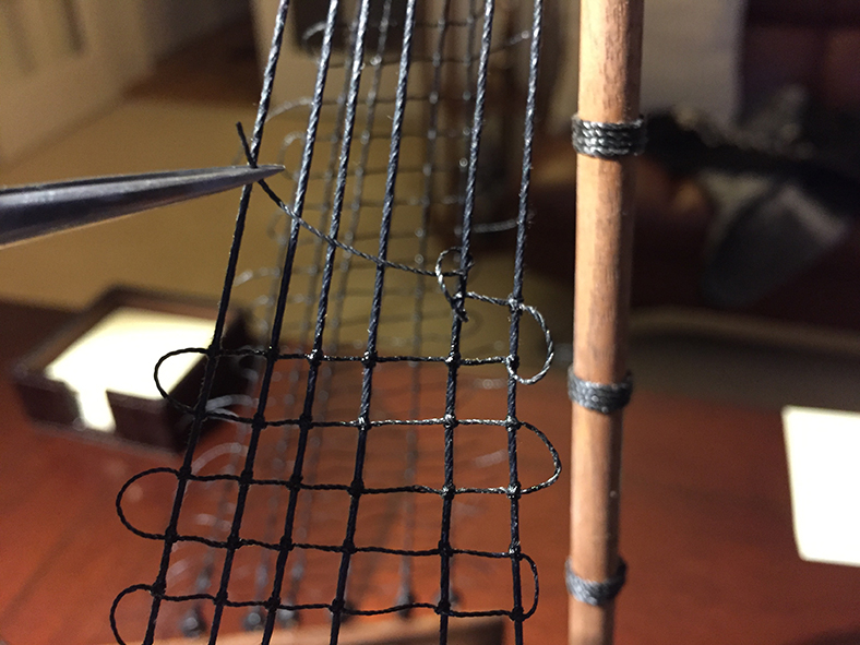
Each knot is a clove hitch, which provides some flexibility but maintains its tension when pulled. Each knot must be tied with the same level of care to maintain the symmetry of the ratlines – as once again, the ratlines are one the most visible aspects of the model an any flaws are more noticeable than other aspects of the ship.
Finishing the ratlines is an important step and, I believe, is a moment when the overall model really starts to take shape and look like a ship.
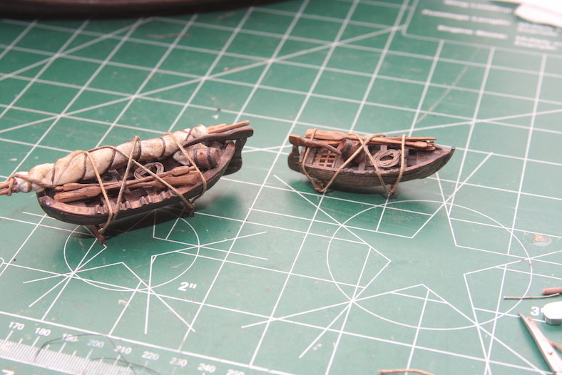
Based on a fair amount of research, it appears as though the Santa Maria had two smaller boats. The first one is located here: The Lifeboat .
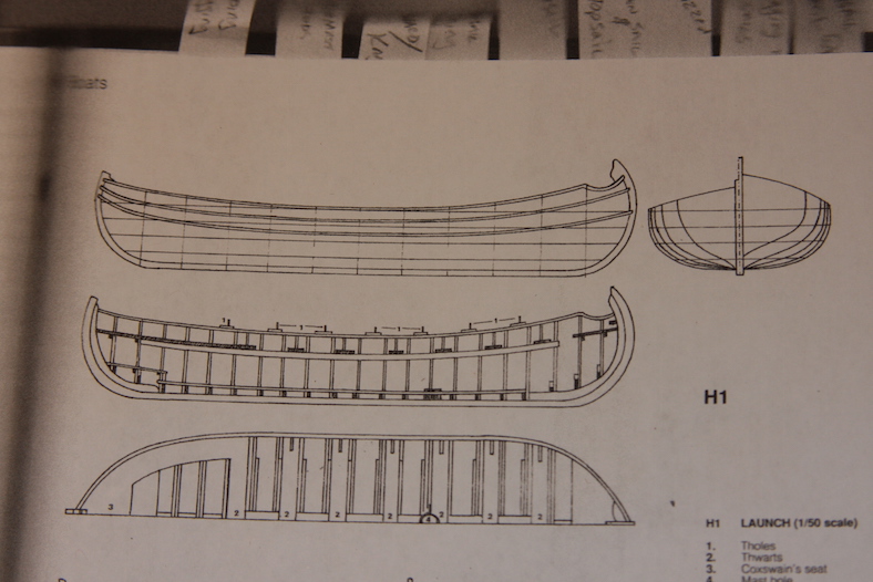
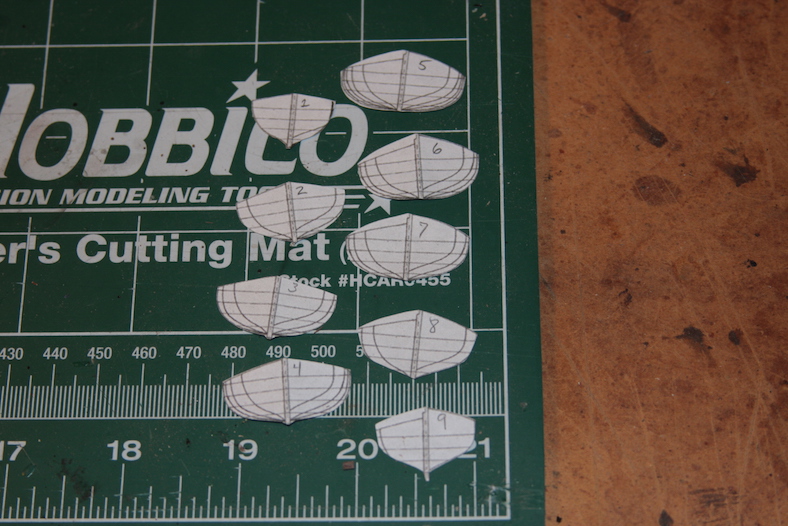
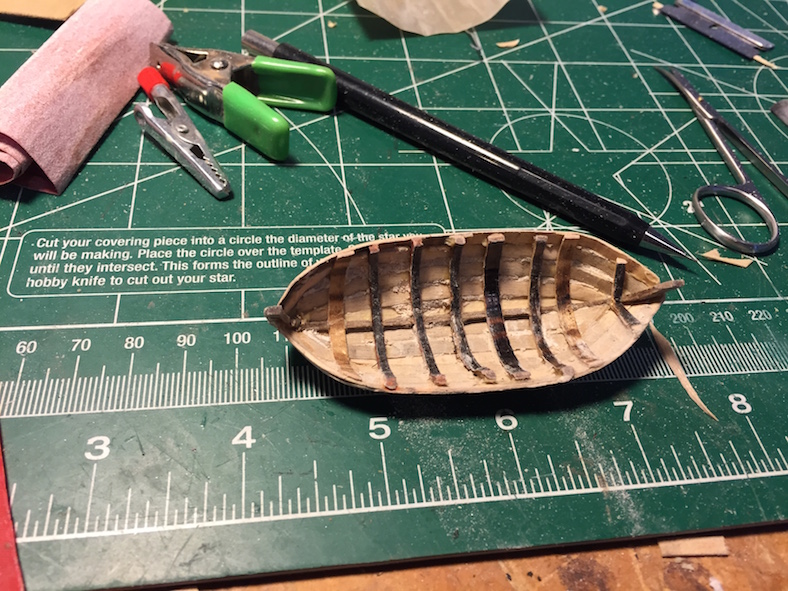
The second, is a larger “launch.” After a couple of failed attempts, I used a similar method that I used with the ‘lifeboat’. I took the diagrams from Pastor’s reference, made scaled copies, then cut out along the lines to create bulkheads to plank.
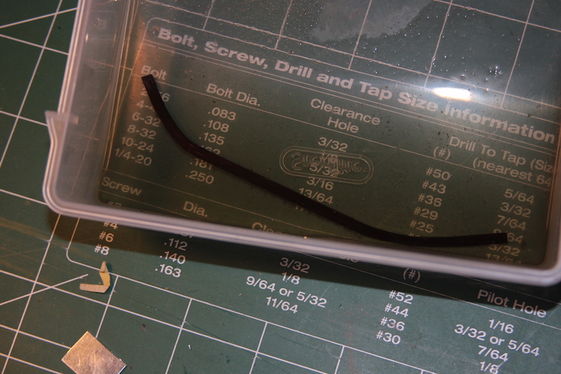
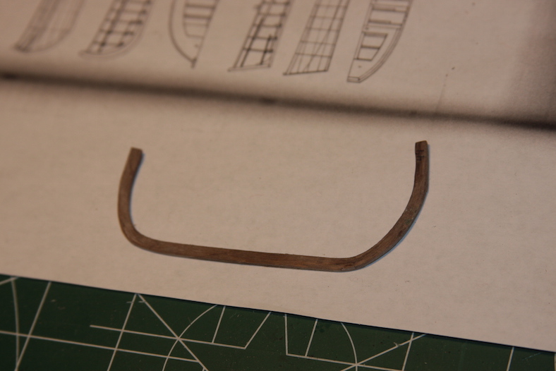
The most difficult part of this small build was shaping the keel. It’s a very dramatic bend. It took several attempts at soaking a strip then bending it with heat to get the shape I needed. I overbent, cracked and broke a number of pieces going to fast. Patience was definitely and ultimately a virtue here. But, I finally got a reasonable facsimile to work with.
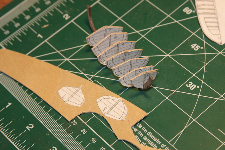
To shape the bulkheads properly, I just glued my paper templates to some thing plywood – knowing I would sand out the hulls later.
As it turns out – this method failed miserably. I wasn’t able to effectively plank or sand this version, because there wasn’t enough wood to work this. After much aggravation, I just scraped the plank on bulkhead idea.
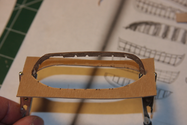
Shifting gears – I switched to a more basic method, trying to simulate the real-world version of building smaller craft. I mounted my bent keel, filed small grooves, then bent and shaped until I came up with something suitable to plank. While this ultimately worked – it was quite difficult soaking and bending these smaller pieces.
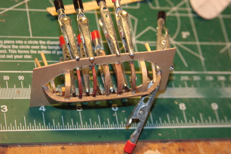
After quite a bit of planking, sanding and filling then planking again – I had a viable product to work with and shape.
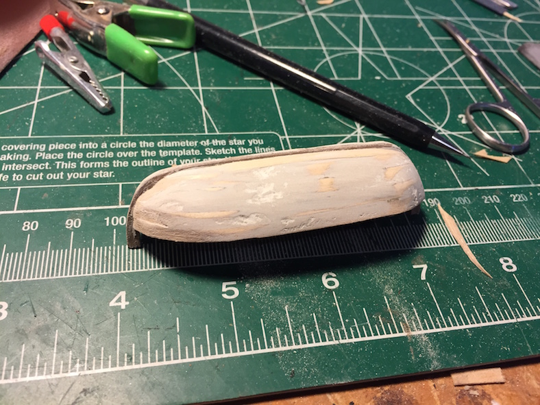
Filling in the launch with seats, rails, and a keel was relatively easy compared to the construction itself. Thank goodness for the weathering that I’ve been using because hopefully it’ll cover up a fair amount of minor inaccuracies.
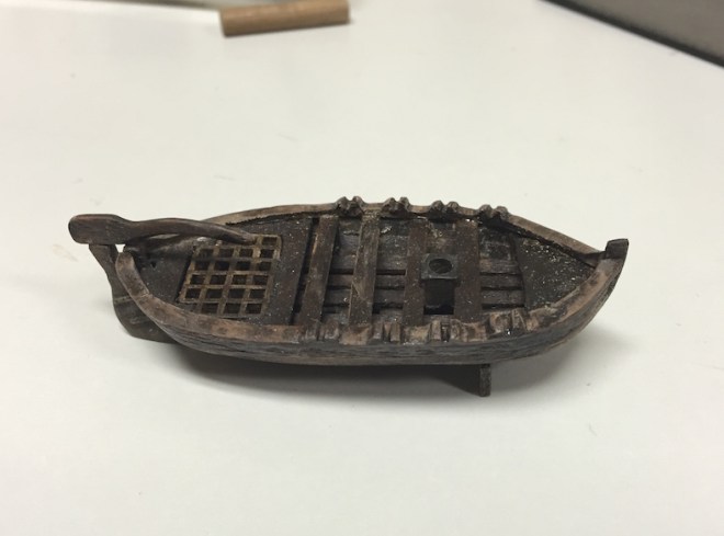
I’ll ultimately also add oars, some rope, and other small additions that represent the clutter that was often found in the small vessels. I suspect they were often used as storage bins much the same way we all seem to have a “junk drawer” somewhere around the house.
A number of different sources make reference to a cook stove on deck of ships from the Santa Maria’s time. Although there isn’t any specific notation about it in Columbus’ logs, etc – that’s obviously not surprising considering it is such a mundane element.
Once again, I primarily used Pastor’s guidance. I constructed the cookstove using a small piece of aluminum put together with solder and JB Weld. The grate comes from a common screen door, and the cookware is wood and wire.


A ship has two basic types of lines that run throughout the masts and deck: standing rigging that holds masts and ship fixtures in place, and running rigging which is used to raise and lower sails and adjust yards and other moveable parts. Each rope and line in both the running and standing rigging is “reeved” or passed through a block or pulley then faceted or “belayed” to the deck with a cleat or rail.
Although the rigging on the Santa Maria and other vessels of the time was very basic compared to ships built in the following century, it is by no means simple. In later ships, belaying ‘pins’ were used, however those items weren’t introduced until the mid to late 1600s, over a century after the Santa Maria.
Before I could layout where the cleats, rails, and sheaves (a small pulley the rigging passes through) I first had to layout the standing and running rigging and where it would terminate on the different decks. Once again, I turned to Pastor’s book to compare the best guess for the rigging with the plans supplied in the kit.
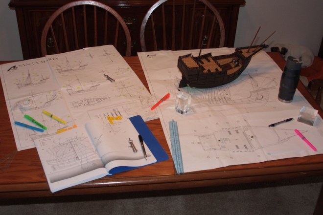
To my surprise, the rigging plans supplied in the kit were quite accurate when compared to Pastor’s rigging. There were however extensive differences between the two when it came to belaying the rigging to the deck. Using the plans supplied, Pastor’s work, Mondfeld’s “Historic Ship Models” and “Vanguard of Empire” by Roger Smith (which contains some of Columbus’ actual notes) I put together my own ‘best guess’ of the ship’s rigging. I then drafted a mockup-up of the ship’s deck and where cleats, sheaves, rails, and deck rings will be located to facilitate the rigging.
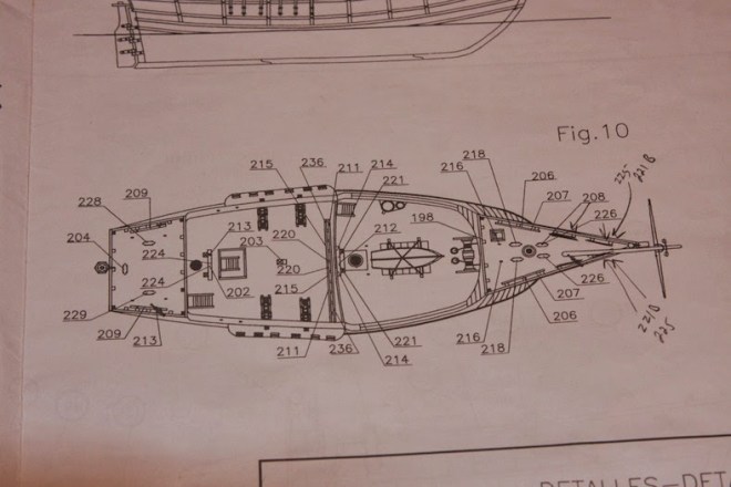
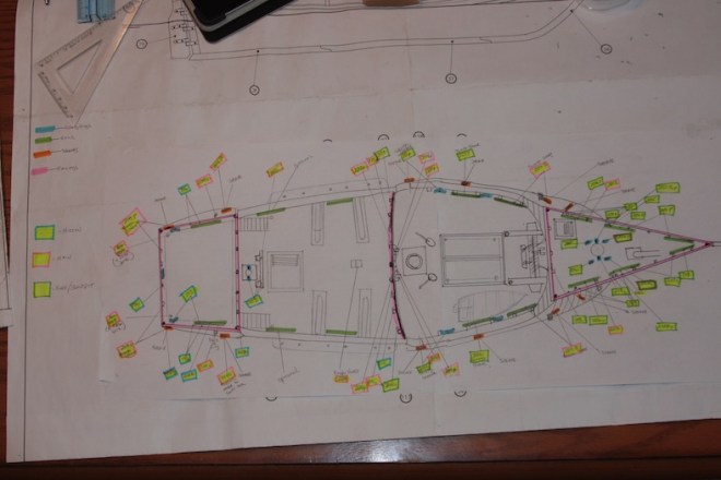
My new layout is color coordinated to reflect rigging to and from the Mizzen, Main, and Foremast / Bowsprit areas. It is only after the creation of the new schematic that I can create the fittings and place them on the ship.
Main Mast RailMost ships have a main mast pin rail to secure rigging from the main mast. The Santa Maria is no different. However, as I mentioned, belaying PINS were not in existence for another century. This was one of my initial mistakes. My first railing contained pins, so I had to go back, take it out, and replace it with a rail with no pins.
The new rail is the built essentially the same as the previous rail and consists of two 4mm x 4mm beveled stanchions and a 5mm x 1 mm walnut piece shaped and notched.
The cleats supplied are rather delicate metal pieces. These actually work fine to add to the sides of the masts (a feature missing altogether in the kit instructions) but are wholly inadequate as deck and bulwark fixtures.
I briefly considered ordering cleats from one of the supply companies that I use, but decided I would be better served making my own. At any rate, I used a very similar process starting with a 3mm X 2mm strip, measuring off every 10mm for the width of the cleat I needed. I used a 10mm Dremel grinder for the bottom of the cleat and a 3mm to 7mm conical shaped grinder for the top.
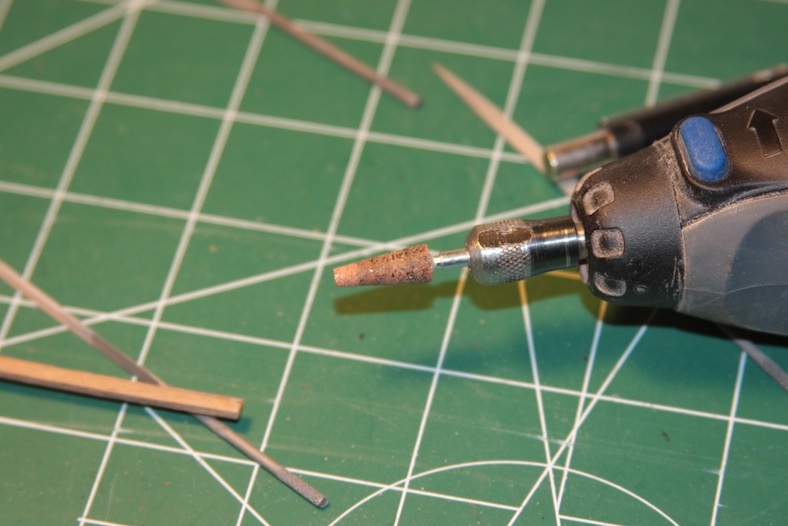
I then sanded and rounded the edges with 400 grit sand paper. I did this BEFORE I cut them apart since sanding any kind of small piece is much easier for me if it’s still on a stem.
It’s important that these cleats are mounted to the deck with enough integrity to hold stiff rigging. To ensure that’s the case, the final step is to drill holes in the bottom of the cleats and insert a pin that will secure the cleat to the bulwark or deck beyond just glue.
Additional cleats are attached to the base of the three masts. For these cleats I notched out an area at the base of each mast and used the metal cleats supplied with the kit.
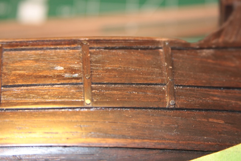
For the most part, sheaves are completely missing from the original rigging plans. My guess is that it is because these delicate fixtures are pretty darn difficult to achieve. The AL version of the Santa Maria is not billed as an “advanced” build, so it’s logical that they would leave out some of the more intricate details that would be too difficult for a novice builder.
Essentially, a sheave is a wheel or pulley mechanism built into either a block or into the ship itself. Rigging lines are run through the sheaves to ease the ability to reeve the lines. According to my rigging research, the Santa Maria has five sheaves on each side of the hull.
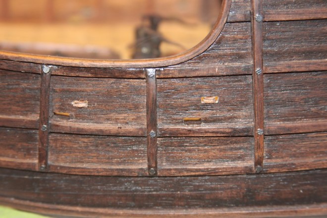
To build in these sheaves I used the same basic process as the sheave blocks. I drill to mark the locations, carve out the space, then insert the small disc that serves as the sheave itself. It ended up being extremely difficult to cut a dowel into a thin enough disc to fit into the hole carved out. My suspicion is that during the rigging process, I’ll need to drill out a slightly larger hole on the edges of the sheave to fit the rigging through. It will very much become a ‘threading the needle’ process.
The bulwark rails are simple features created with 2mm x 2mm strips of walnut secured with mounting brackets also made of walnut. Like the cleats, these rails must withstand rigging knots, and so are also secured to stanchions or bulwarks with metal pins.
One of the challenges I faced was installing the rails on the poop deck while maintaining enough room for the deck to open so we could see the captain’s cabin. If I had the proper foresight, I would have made this measurement BEFORE cutting and hinging the deck. However, since that wasn’t the case, I needed to adjust the depth of the railings instead.
The standing rigging whose primary job is to hold the masts in place are called the shrouds. The main mast shrouds are attached through planks attached to the hull, then secured to the hull itself. Attaching these rails drew my attention to an aspect of the futtock riders that I overlooked earlier in the build – securing them with larger trenails. An oversight that I took this opportunity to correct.
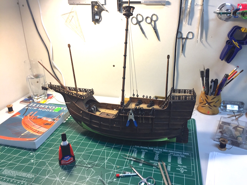
With the basics of the decks laid out, and the foremast and bowsprit in place, I decided it was time to loose fit the main and mizzen masts so I would have a better idea of exactly how much room I’m going to have on the decks, as well as get an idea of how I will need to alter the rigging from the original plans.
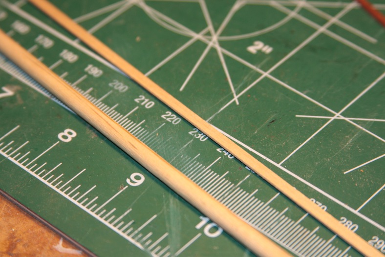
Step one for the both masts is to size and taper them. My technique goes back to my makeshift lathe using my power drill, then sand it down to the desired diameter at the top. The mizzen is obviously far less complicated than the main.
The next step is to decide on the base mount for the masts. The AL kit supplies circular, brass coated fittings that I think may be pewter. They not only look pretty cheap, but they’re not very well made. I prefer square mast bases anyway, so I built my own and beveled them.
As I stated, the main mast is more complicated. The base of the mast is bolstered with vertical strips of wood to strengthen it, then it is wrapped with heavy gauge rope up the length of the mast.
Not long ago, I ordered 2mm x 2mm strips of walnut for a variety of needs including futtock riders. What I got (I think it was from Bluejacket) were these horribly ugly and DYED strips of wood that look like they were painted some sort of mahogany.
So far, I only used them for inside the captain’s cabin to give it some color. I decided to use those strips for the base of the main mast – once again to add a little color. Particularly since I used a unique piece of wood for the base.
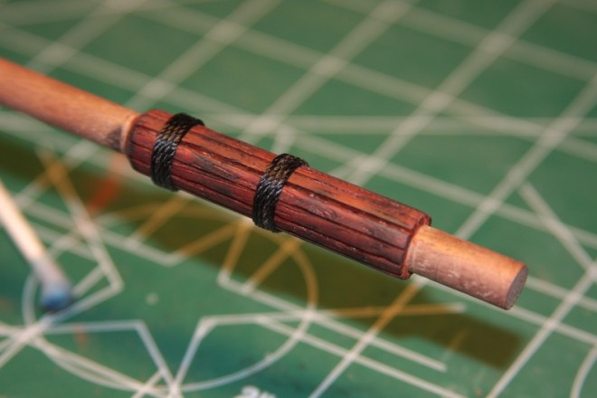
At any rate, the strips are cut and mitre’d on the edges so they fit together adequately around the mast. Finally they are glued, then the ropes are added and tied as per Mondfeld’s “Historic Ship Models” in which the ends are tucked in to the back of the mast.
The top of the main mast in the AL documentation supports a couple (at least) of blocks. However, a more accurate representation is a double sheave block. That block is created by to walnut pieces sanded to fit snuggly against the mast. The sheaves themselves are narrow cuts from a spare 5mm dowel. The big challenge here was getting everything to fit snuggly.
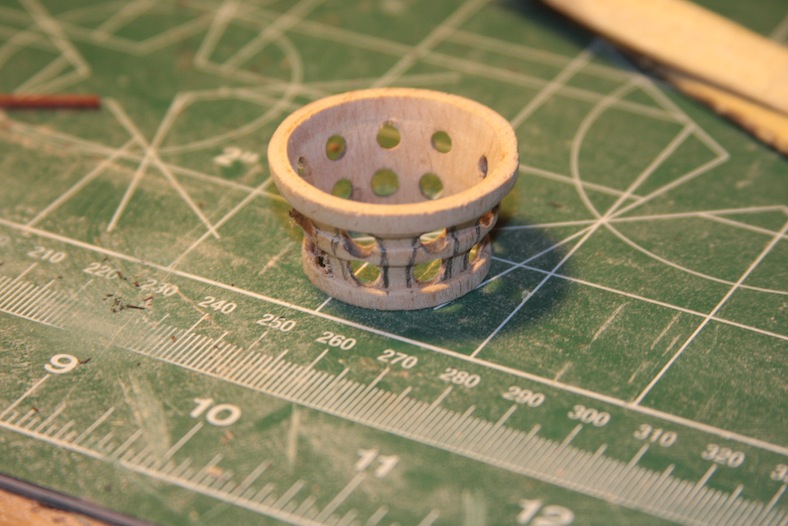
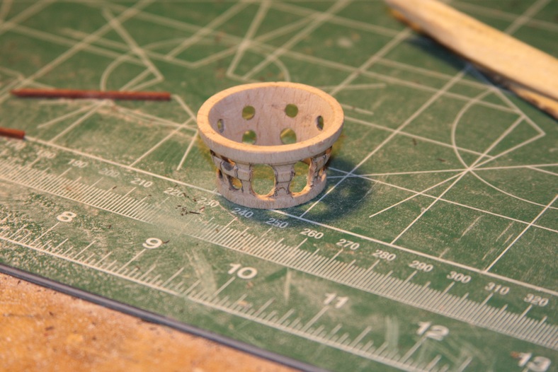
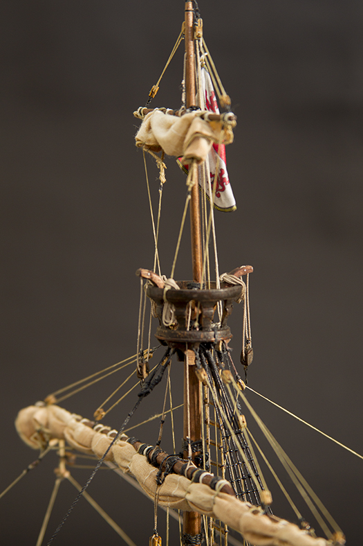
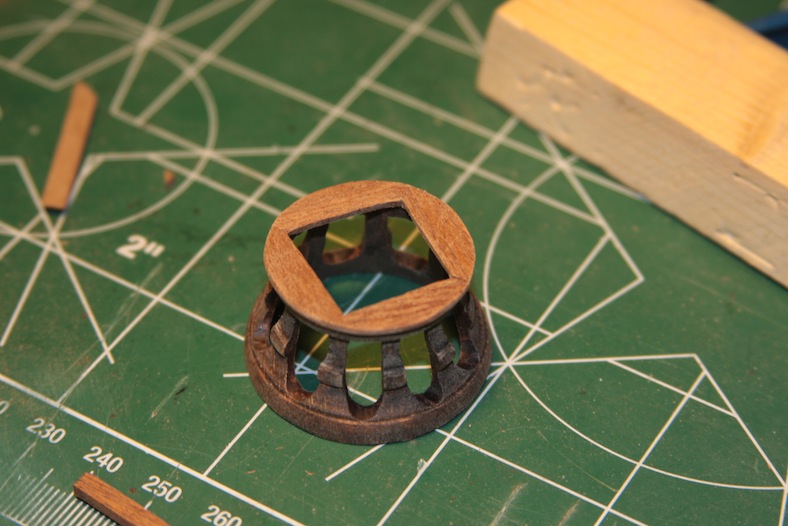
The main mast of course houses the crow’s nest. The crow’s nest supplied is a solid wall, poorly molded version. At first I started rebuilding the entire thing from scratch, then realized that I could probably just refit the one supplied.
I measured and marked, then drilled out holes in the sides. A lot of sanding later I ended up with something that I liked and that was quite a bit more accurate.
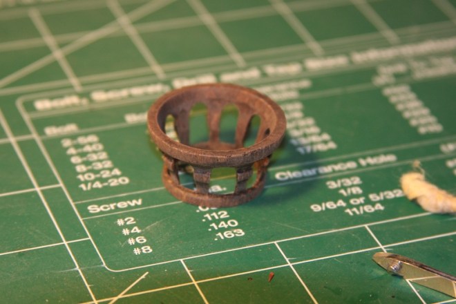
The base of the crow’s nest is simply four mitre’d 5mm walnut pieces that are rounded and fitted to size. The entire thing sits on your typical criss-cross structure that will also provide a base for the topmast. Getting these pieces to all tie together nicely required a fair amount of clamps.
The important aspect of the topmast is the rounded sanding at the base to ensure it fits snug against the main mast while still accommodating the double sheave block after it is tied together. The final steps are to stain and/or tung oil the pieces to make them meld together while still showing the details with different grains of wood.
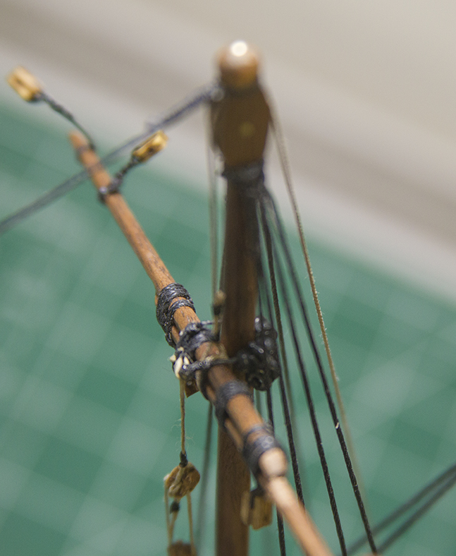
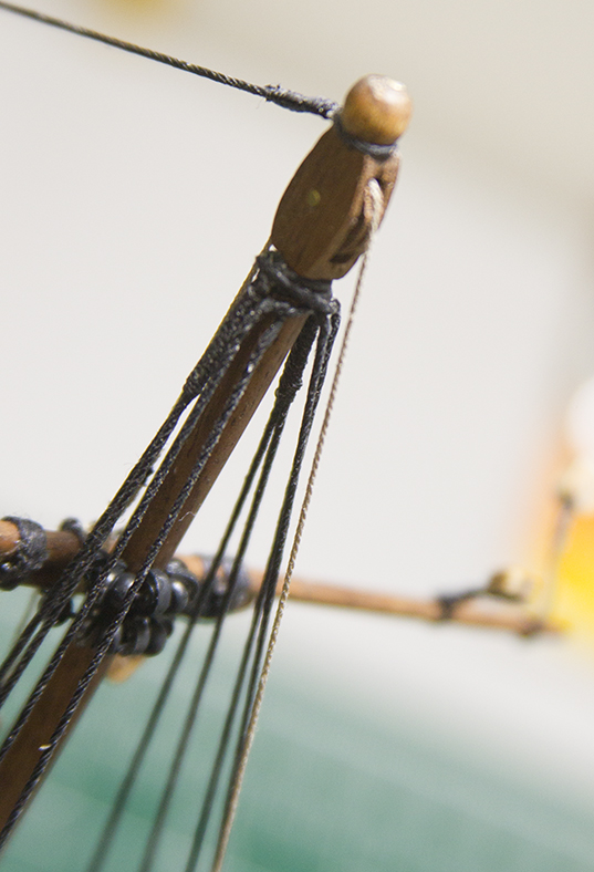
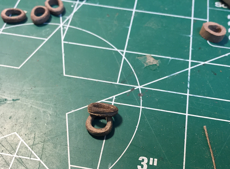
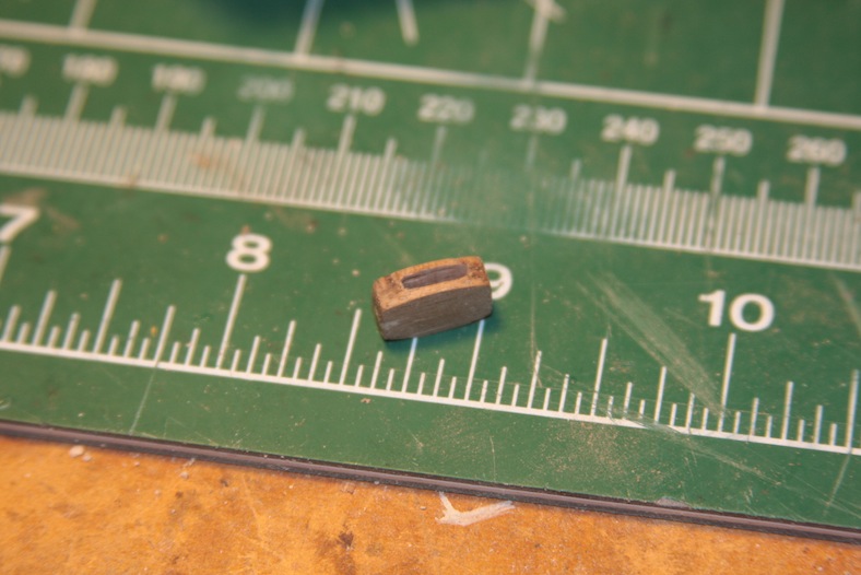
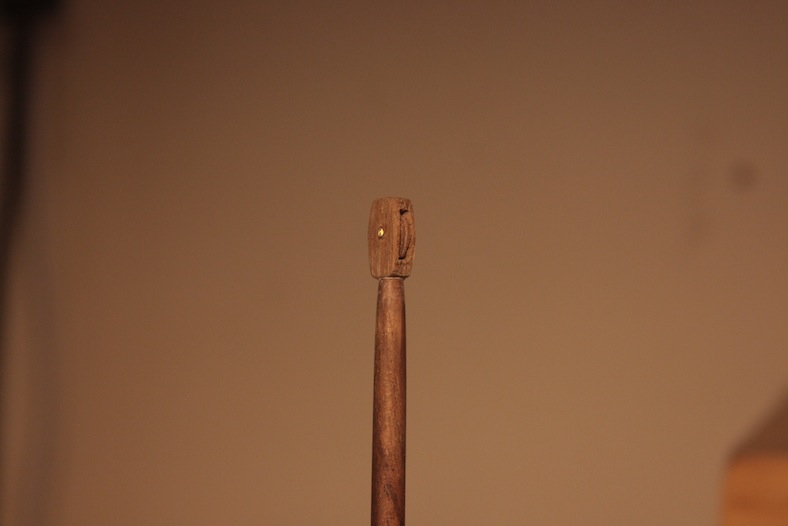
The final aspect for the masts is the sheave block (essentially a pulley) added to the top of the masts.
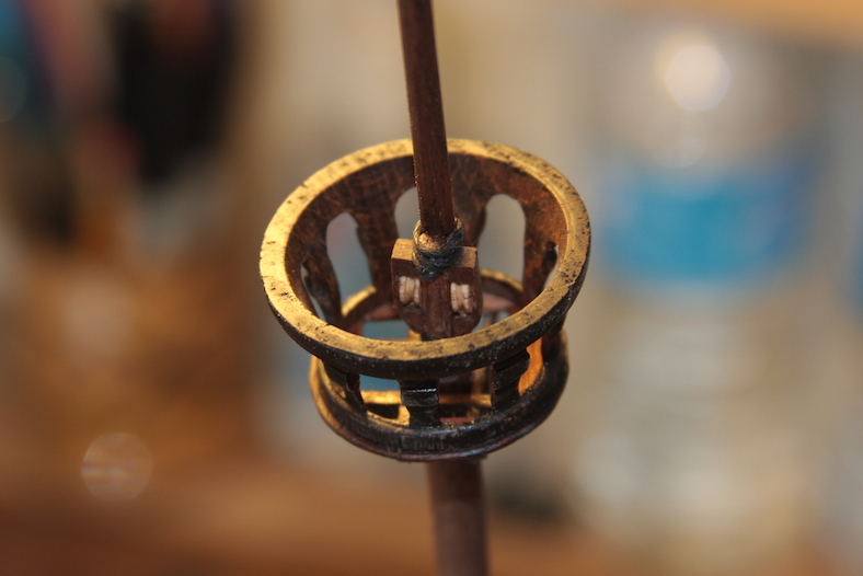
The sheave block is made from a piece of walnut, drilled and filed to create an opening. The opening is filled with the circular “pulley” cut from a leftover walnut dowel. The piece is sanded down to fit, placed into the block’s opening, and secured with a brass rod through the center of the entire piece. The sheave block is then secured to the top of the mizzen and fore masts with glue and a pin.

After the masts are built, the touchy part comes into play. Holes must be drilled into the decks. Obviously this is an awfully nerve-wracking step. Any mistakes here are nearly irreparable and would be very difficult to mask. Each hole is initially drilled with a very small bit at a very high speed to minimize tearing the delicate wood of the deck. The holes are widened incrementally using larger bits until it gets close to the desired diameter. The holes are then finalized with a high grit sand paper to achieve as tight a fit as possible.
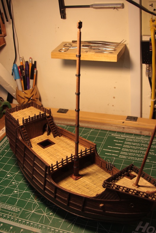
The masts are NOT secured in place yet, but are dry-fitted.
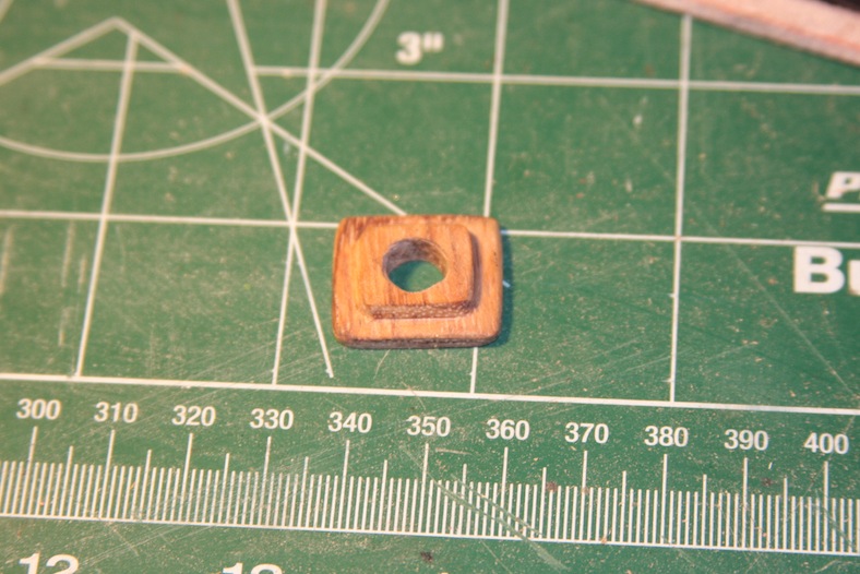
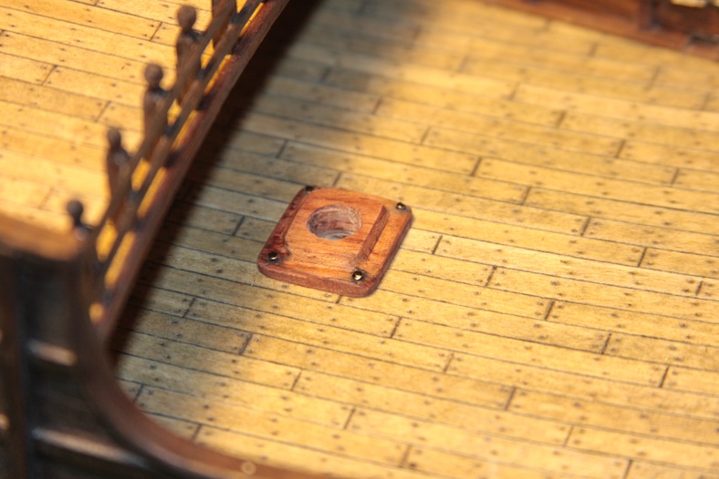
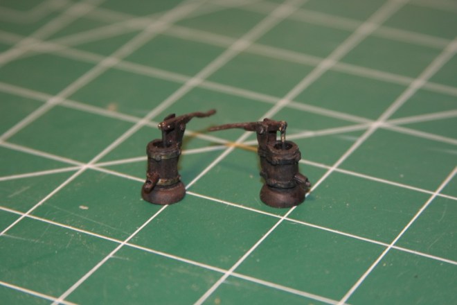
Although the Xavier Pastor book I have been continually referencing lists the Santa Maria as most likely having a single turn-crank water pump, every other reference I’ve seen has shown a more traditional pump-handle style water pump. Often times there are two, as in later ships. When it comes down to it – I think the pump-style handle looks better, so I went with that.
Then I came across this research from a fellow shipbuilder from “Vanguard of Empire – Ships of Exploration in the age of Columbus” by Roger C. Smith.
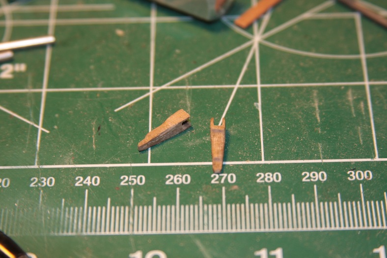
“Fifteenth and sixteenth century ship’s pumps consisted of three main components: a pump shaft, a piston rod and valves……early suction pumps worked on the simple mechanical principle of drawing water up through a tube…… with a one way valve.The pump shaft was fashioned from a a straight tree trunk …or fashioning a tube of individual planks, like the staves of a barrel…..The base of the pump shaft in the bottom of the bilge was fitted with a foot valve made up of short baulk of bored wood fitted with a leather flapper valve on top……..Water usually exited the pump tube through a hole in its side near the top above deck level.
On the fourth voyage, Columbus was forced to stand for Jamaica, “especially since the ships were so eaten by shipworms, that day and night we never stopped pumping water with the three pumps. If one broke down, kettles were substituted for the job while it was being fixed. Despite these efforts, the caravels could not be kept afloat and at God’s mercy, we beached in Jamaica.”
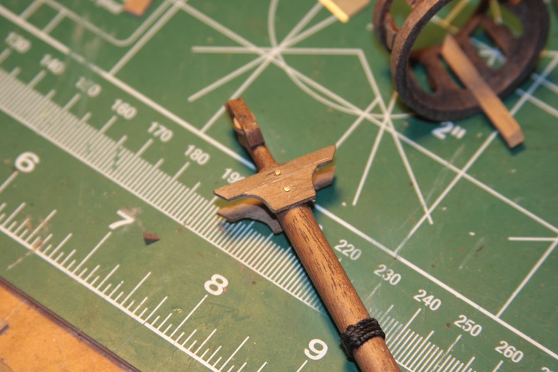
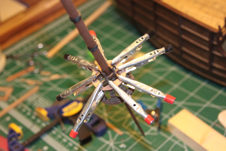
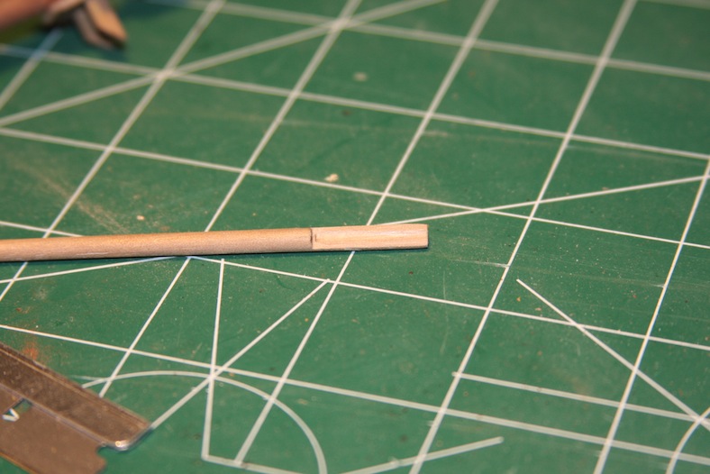
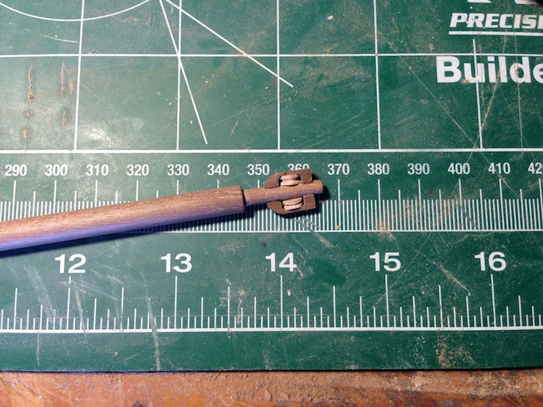
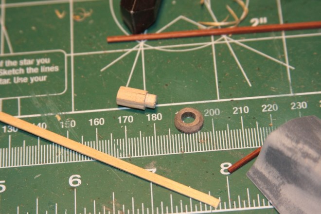
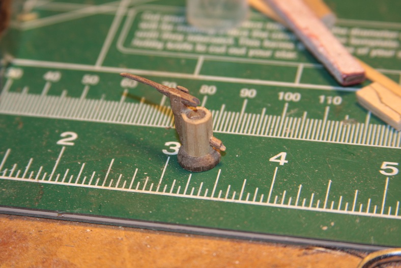
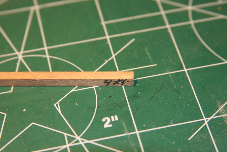
To build my water pump I started with a 5mm diameter dowel and thin basswood strips.
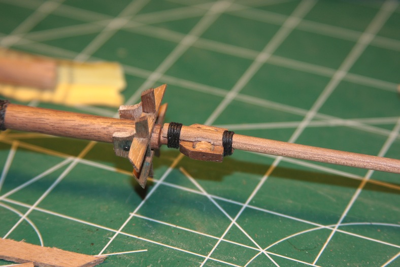
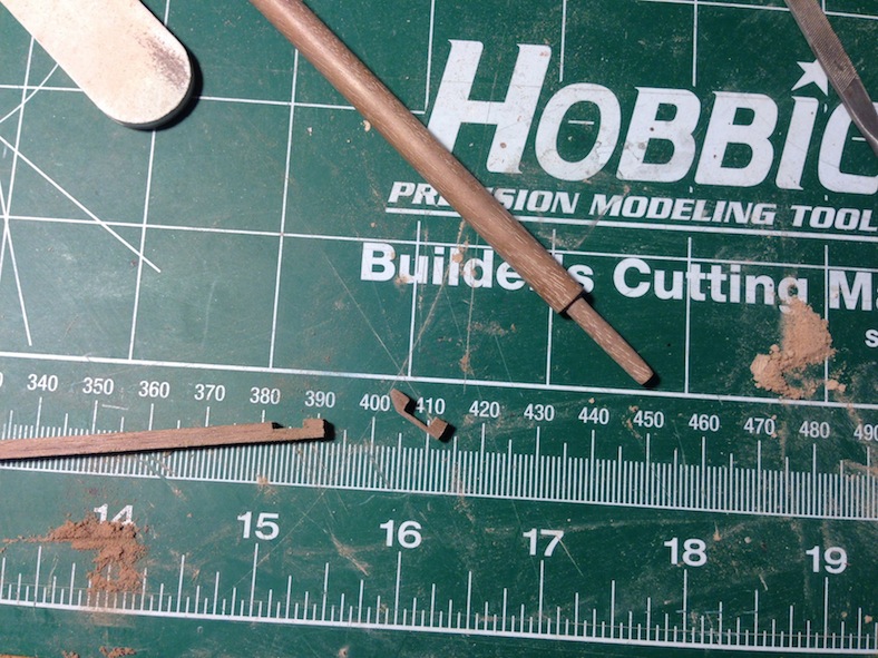
I trimmed the sides of the basswood strips at a 45 degree angle so they would fit together mitre’d nice and snug. I then cut them at 15mm lengths and glued them around the dowel to create the base of the pump. I went with this idea to create a solid base that wouldn’t collapse when I started working on it.

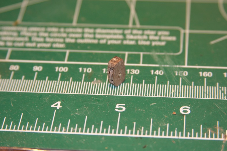
I then hollow out the base of the pump with a drill. The base is made from a 10mm dowel of walnut with the center drilled out at 5mm to accept the base of the water pump. Of course the sides of the base are sanded and beveled.
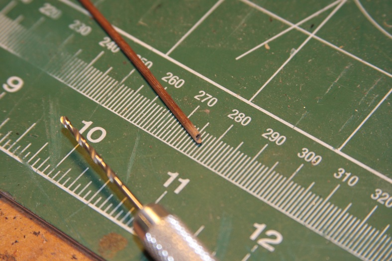
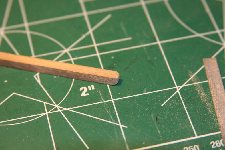
The spout of the pump is a 2mm dowel of walnut with the end drilled out hollow first with a 1mm hand bit, then with a 1mm etching bit for a dremel at low speed.
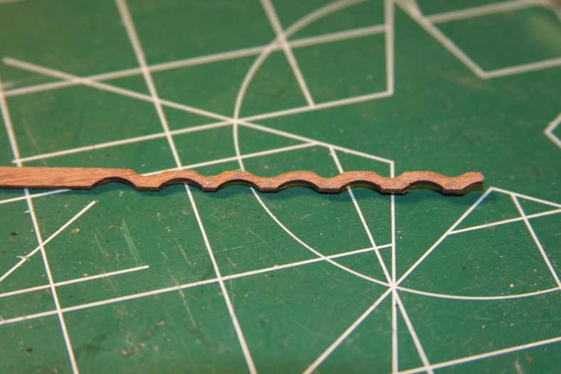
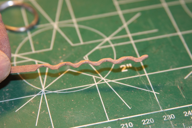
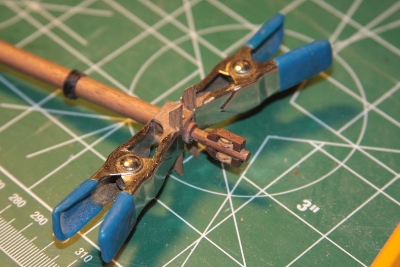
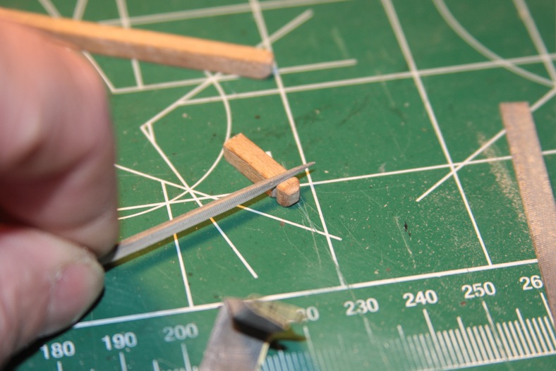
The handle of the pump is created from two strips of 2mm x 2mm square walnut sanded and etched out. They are based in 3mm x 3mm square walnut strips sanded to fit the side of the pump. Then the pieces all put together initially and then stained.

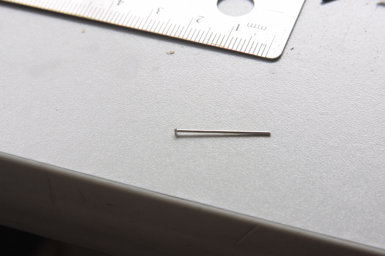
The pump mechanism and the strips around the pump are made from a scrap brass dowel and scrap brass flattened pieces. I flatten the end of the brass dowel out by putting it between the flat areas of a pair of pliers and striking it with a hammer.

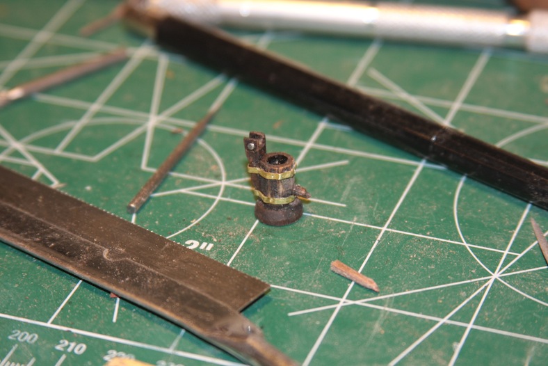
All of the strips, the handle, and the pump mechanism are attached using a touch of glue, and then firmly attached using pins with the heads sanded down. Finally the pumps are re-stained, and the brass pieces are given a layer of patina.
Like anything else with the Santa Maria there seems to be a variety of speculation regarding pinrails, cleats and the like. I’ve had to scan the rigging over and over to try and figure out where these fixtures would have been.
I’ve also been trying to speculate whether or not the belaying pins are more traditional looking (as they are with more modern ships) or whether they may have been more primitive in nature like some of the cleats appear to be.
So, like the rest of the model I’ve looked at many of the builds and references that are our there and then pressed on with what I think works best while maintaining a credible level of accuracy.
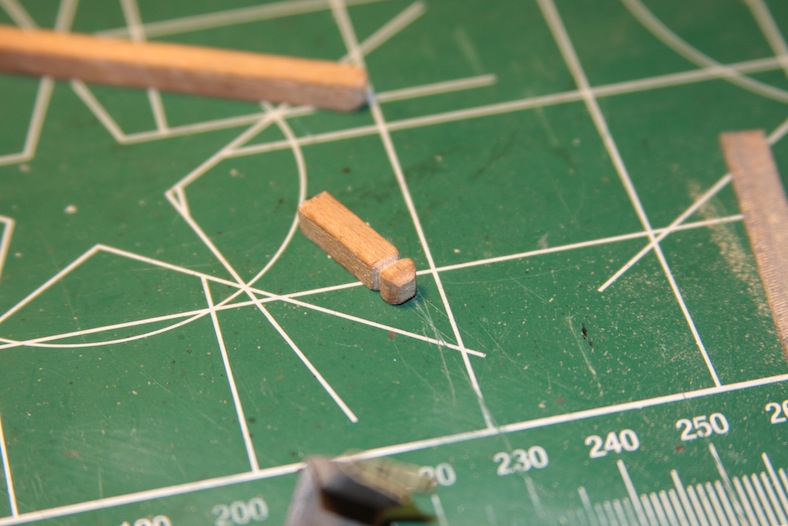
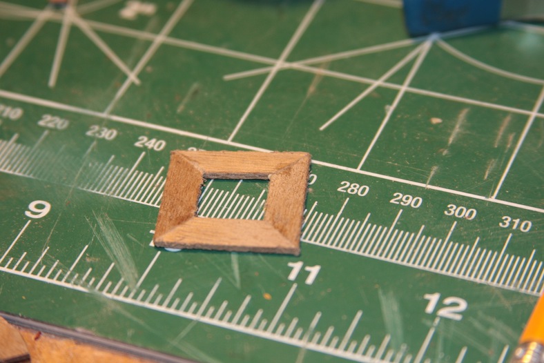
I used a 4mm x 4mm piece of walnut and bevelled the top edges. I’ve stayed away from much ornamentation on this build because I truly believe the Santa Maria had very little. However, I wanted to include a little bit of craftsmanship that I think every vessel would have likely had. So, I used one of my mini pin-files (which sounds redundant) to notch out the top of the posts.
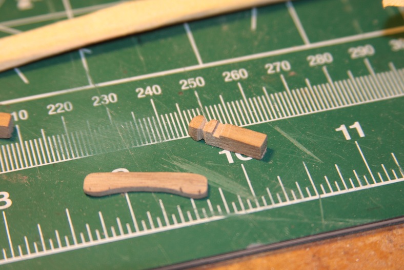
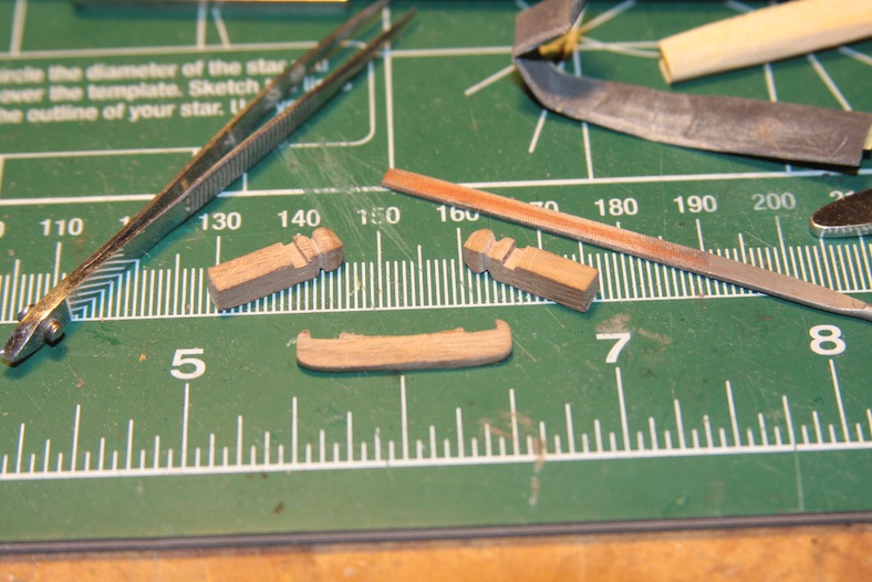
I used a 1mm thick 5mm wide piece of walnut and sanded it at a curve for the rail portion of the piece. I then notched out both the posts and rail to give them a nice tight fit. After staining the entire thing in “Kona” colored stain (to match the weathering I’ve done on the rest of the ship) I put them all together with the belaying pins.
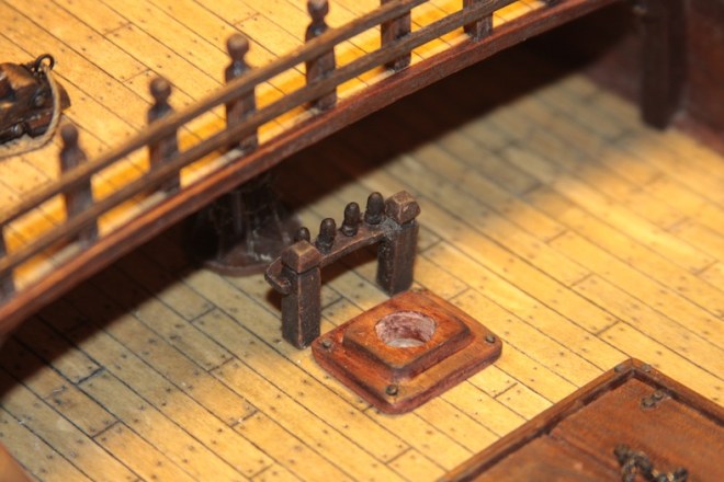
Although it’s not clearly seen here, I mounted the entire piece in the same method that I’ve done railings and stanchions – which is to drill and mount pins in the bottom of the posts, drill corresponding holes in the deck, then mount the piece with a touch of CVA glue. It’s always a challenge come rigging time to get these pieces to hold well once the running rigging is attached and pulled tight.
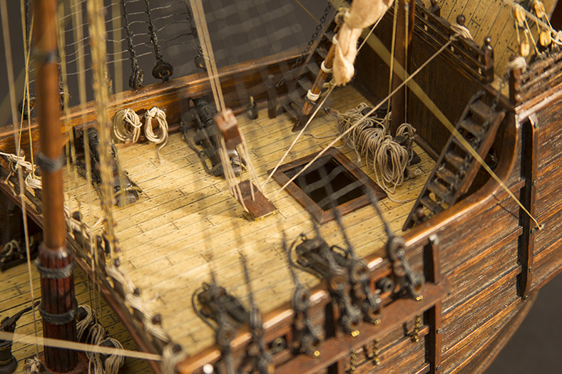
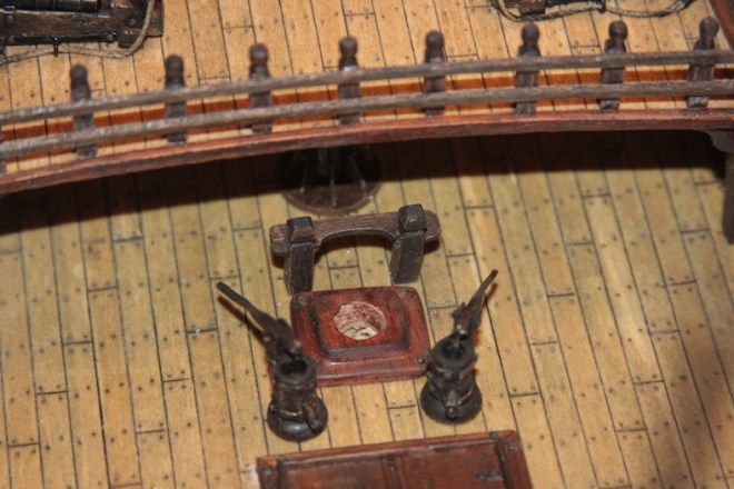
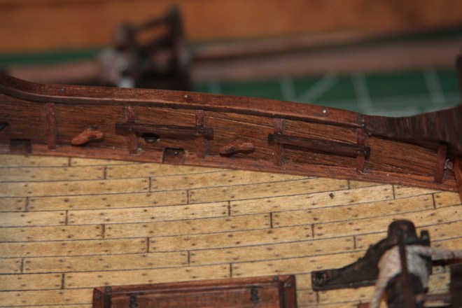
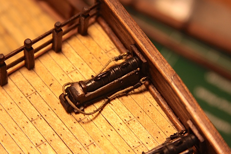
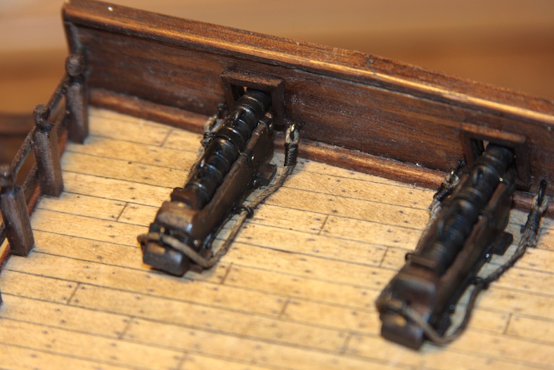
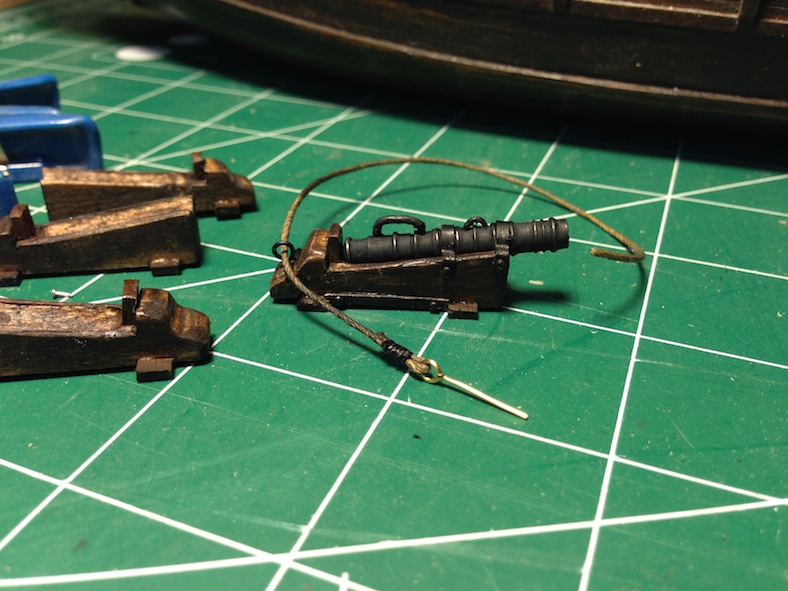
The rigging of the bombards is very basic and was relatively easy to accomplish. However, it drives me crazy when the ropes and rigging stick up further than they need to. This is a natural byproduct of using tiny little string instead of actual heavy rope that would lie naturally. So I used a couple small dabs of CA glue and tried to position the rigging to look as though it has fallen naturally to the deck and along the bombard base.
Here is a before and after.
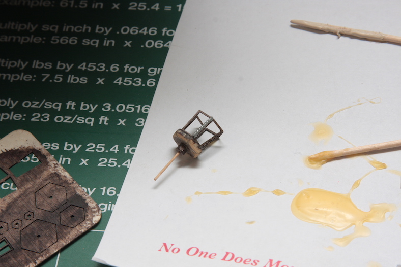
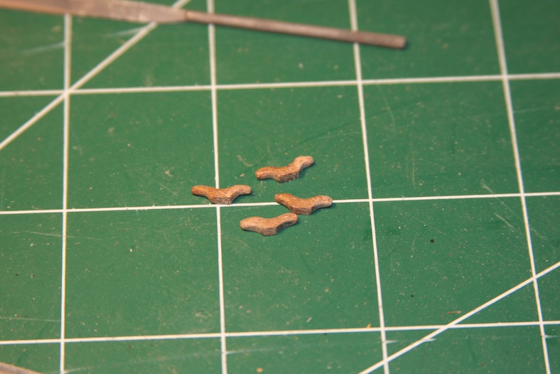
Like most kits, the bombards (cannons) included in the AL Santa Maria fell very short of authentic. Although the die-cast brass cannons themselves were pretty close, the base on which they were to rest were woefully inadequate. So, once again, I turned to Pastor’s reference material.
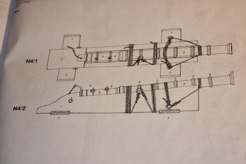
However, this was also an area where I didn’t mind shifting slightly from authenticity. I also like the cannons created by Garik Grigoryan used in his rendition of the Santa Maria. Although much of his Santa Maria is a little too elaborate for my taste, I really enjoy his miniature deck fixtures.
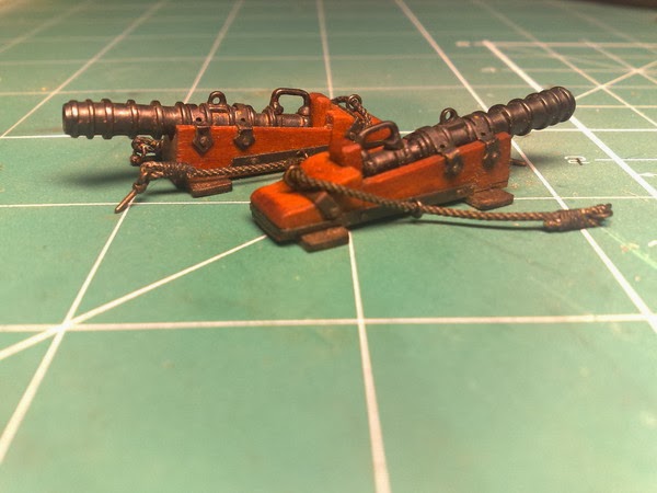
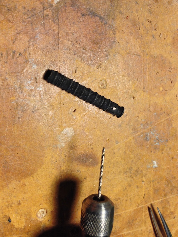
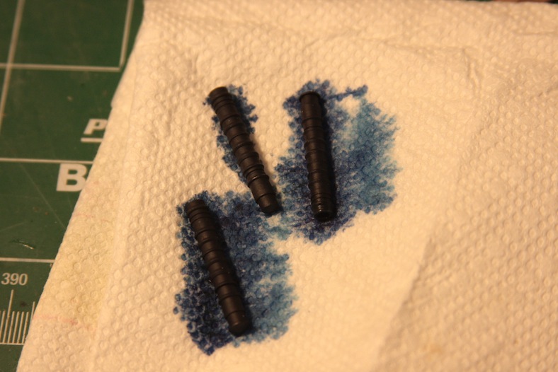
I started with my bombards by letting them soak to create a patina coating. I then drilled out places to attach fixtures.
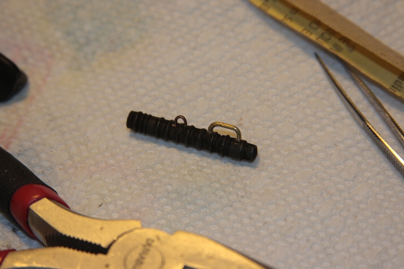
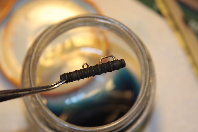
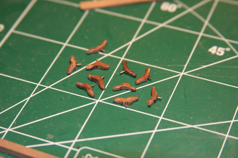
The handles and loops are shaped brass wiring. I then re-soaked the entire fixture to build up the patina once again. Unfortunately the patina didn’t build up as nicely as I would have liked, so I added some paint and other methods for aging as well – which I will get to.
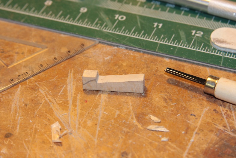
I carved the base pieces out of solid blocks of wood using both hand tools and a dremel. After the bases were carved out to hold the bombard barrels, the feet and backing are added, each is stained. The metal strips are cut and molded brass strips. The rivets are straight pins cut short and inserted into pre-drilled holes through both the brass strips and wood.
I then used this fantastic product I came across by Tamiya.
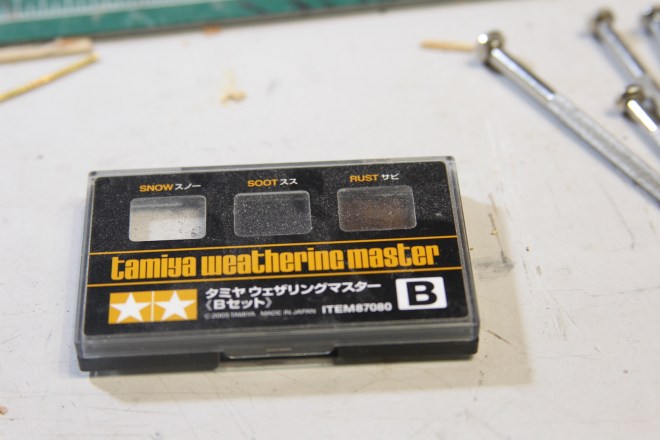
The trick is to add the fake soot and/or rust to a slightly damp product. In my case, I sprayed each piece with a thin coat of polyurethane then added the weathering product. Additionally, I painted the brass fittings that would not patina properly, then coated the entire fixture with the soot just before the paint dried entirely.
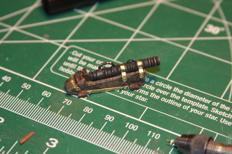
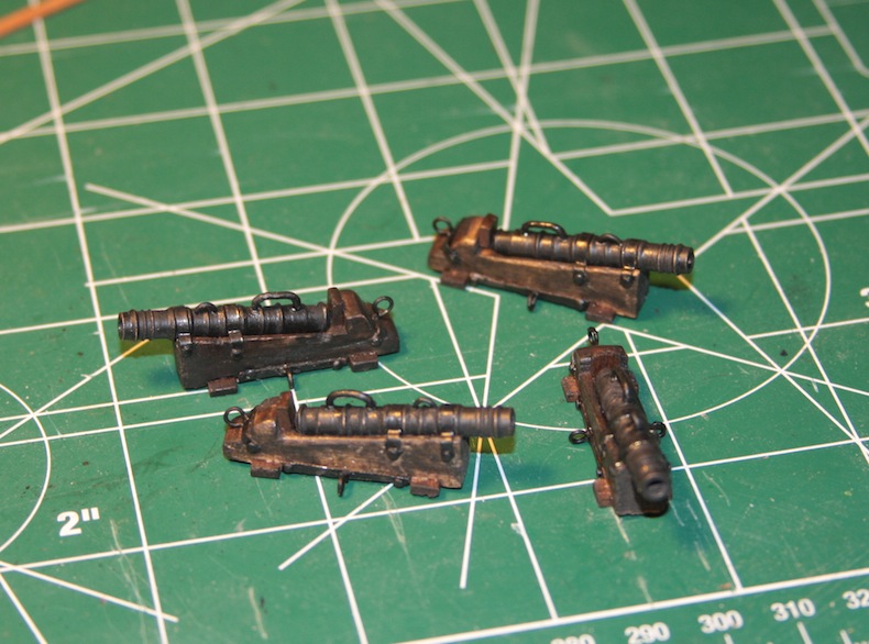
I was very pleased with the final product.
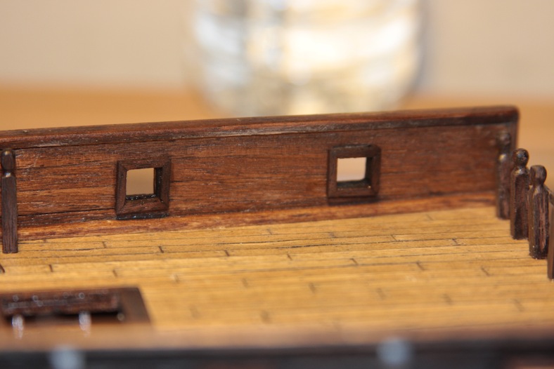
I then moved on to the gun ports in the side of the ship. It always makes me very nervous to cut into the ship. Obviously making any kind of error would be very difficult to correct. So I spend quit a bit of time planning before I actually cut into the ship.
After measuring where each gun port will be and drawing it in place, I started by drilling small holes to outline where the ports will be cut out.
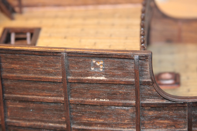
I then used a larger bored carving and etching dremel tool to get close to the sides of the gun port. The rest is done by hand using pin-files. It’s a very slow sanding and filing process because it’s very easy for the siding and planking to fray, crack, or break off.
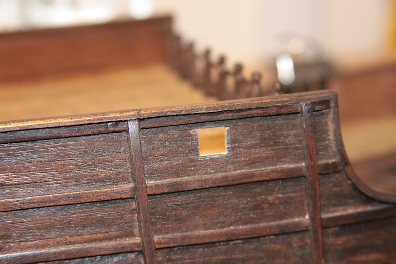
The outside of the gunports are framed with thin strips of mahogany that is mitre cut and mounted. In these cases I used “super” glue since the pieces are so delicate.
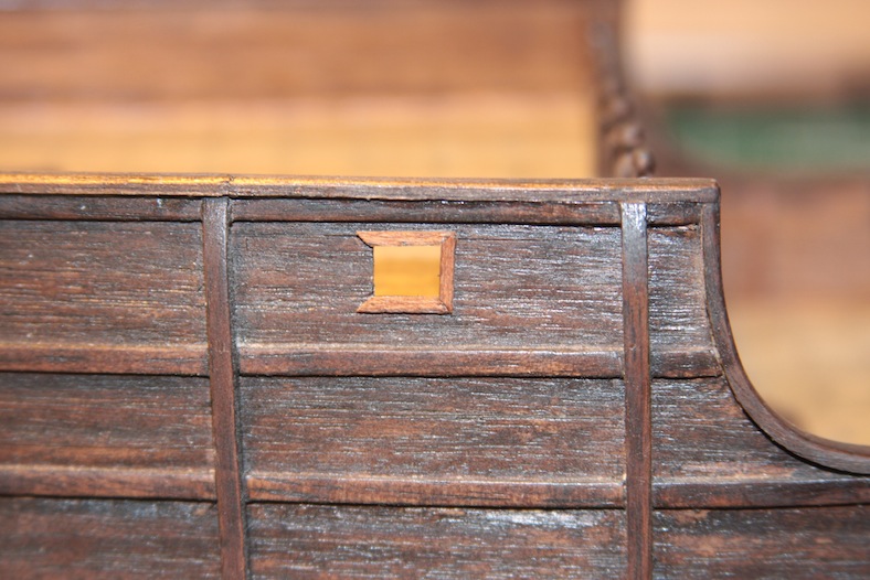
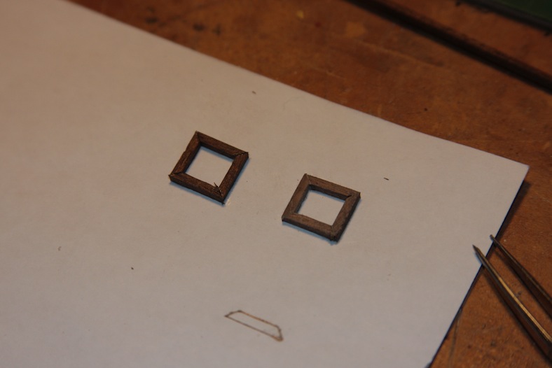
Since I always have difficulty creating frames this small, I used a technique similar to when I created the pieces for the captain’s cabin. After pre-staining the wood, I cut and glued the 2mm x 2mm strips to a piece of paper. This makes it MUCH easier to eventually mount to the gunports.
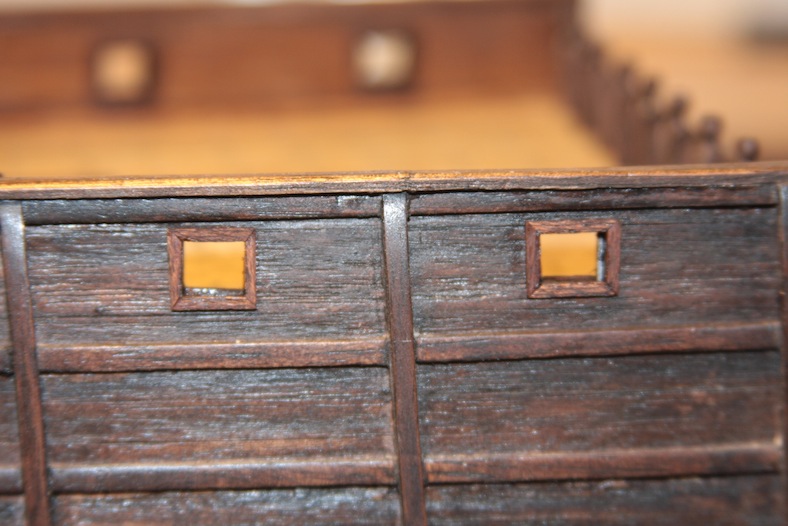
After the glue dries, I use a fine X-acto knife with a new and very sharp blade to cut the paper from inside the frames. I then lightly sand the paper side until it is thin enough to not be noticeable on the final product. Each frame is then glued, sanded again, and stained.
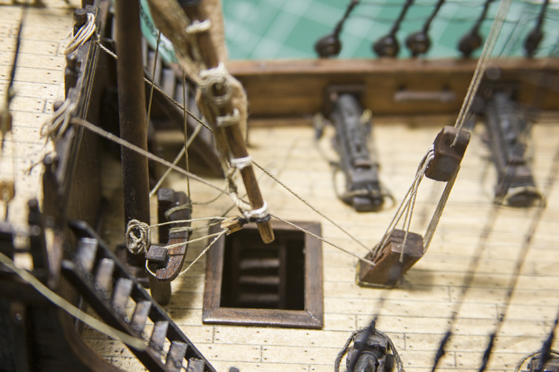
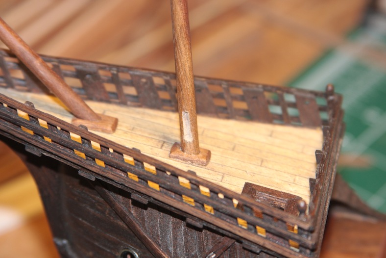
Once the Fo’c’sle has been constructed, the foredeck has been mounted to it, and the head beam is put in place, I was able to add both the bowsprit and foremast. Unlike later ships in which the bowsprit and foremast are mounted separately, the Santa Maria’s bow masts are linked together. This made for a very tricky process.
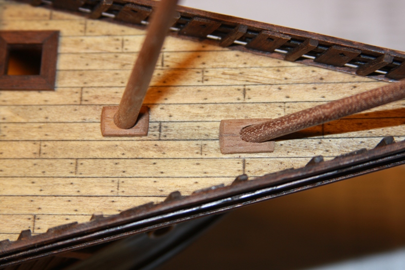
The technique involved putting the two masts in place while the foredeck was unattached. I then bound the two masts together at the proper angle at their base. The patience then kicked in when it was time to mount the foredeck while matching up where the masts enter the main deck.
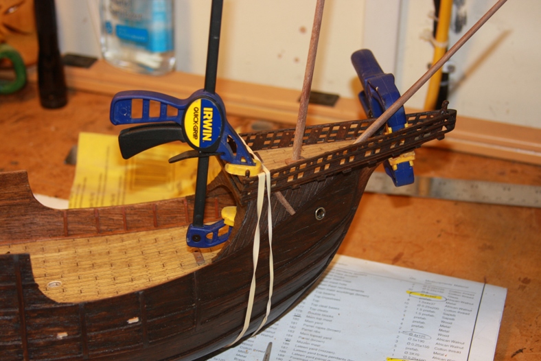
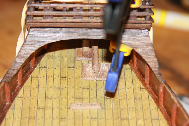
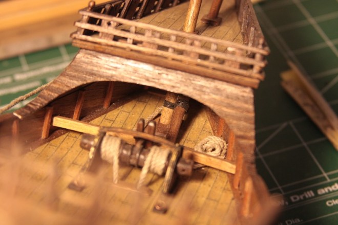
The final product with the head beam and windlass in place looked pretty good. It all makes me realize just how little space the sailors had to run around and actually sail the ship.
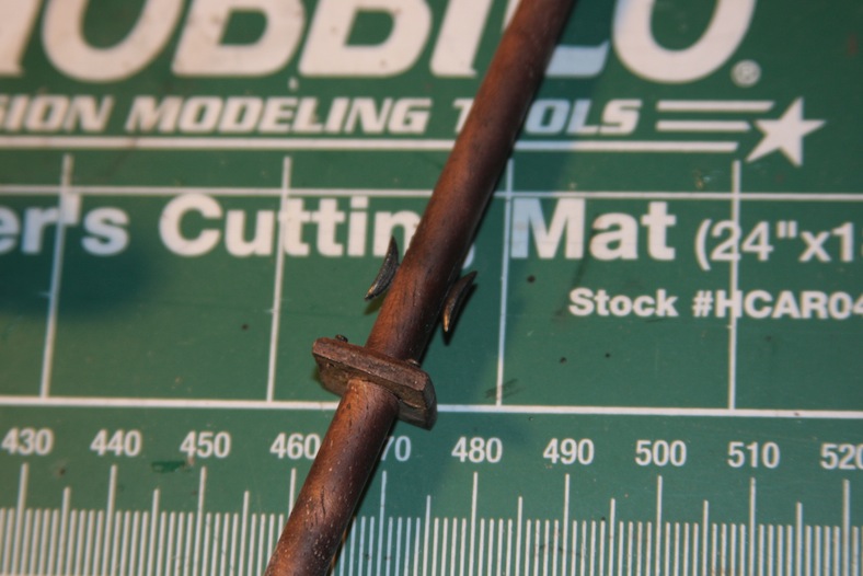
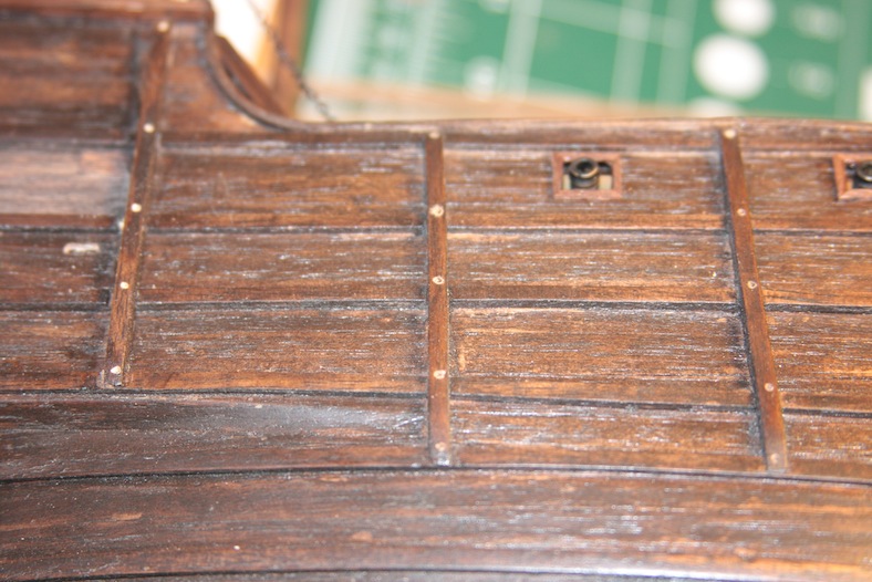
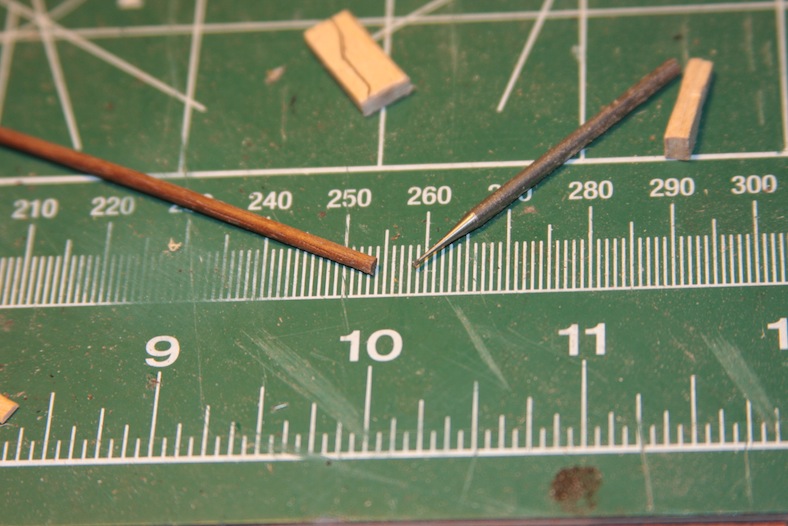
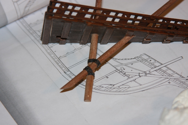
To ease the tension of the rigging, the lines go through holes in the foredeck and around pulleys called reeving sheaves. To create these sheaves, I first drilled holes into the foredeck clinker planking.
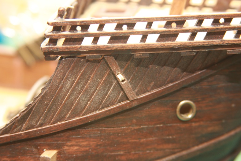
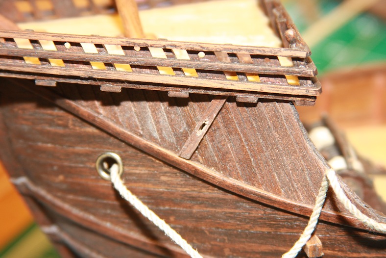
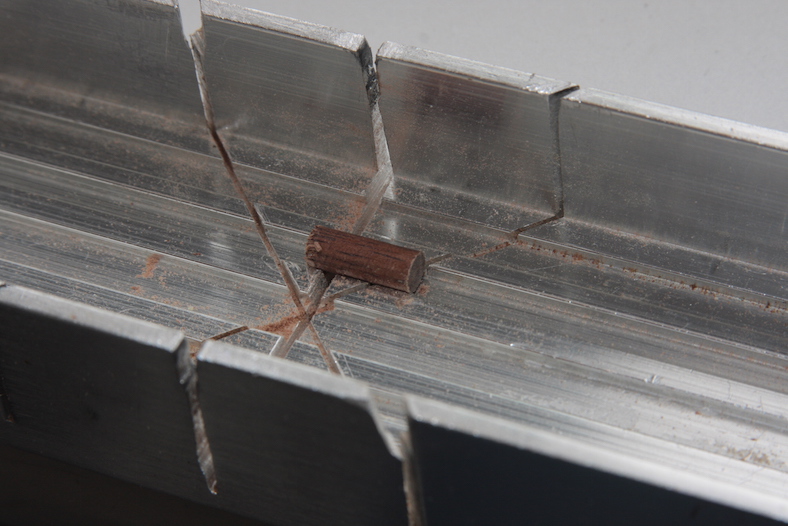
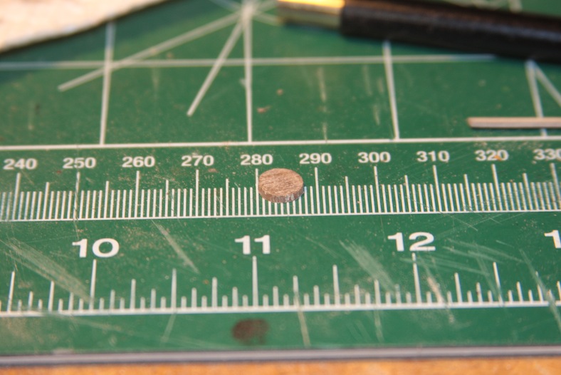
Then I created the pulley by cutting off the end of a dowel and grooving it.
The ladders are created exactly how one would expect – each piece is cut then glued together. It takes a great deal of patience and persistence to glue the ladders with all of the “steps” even and secure.
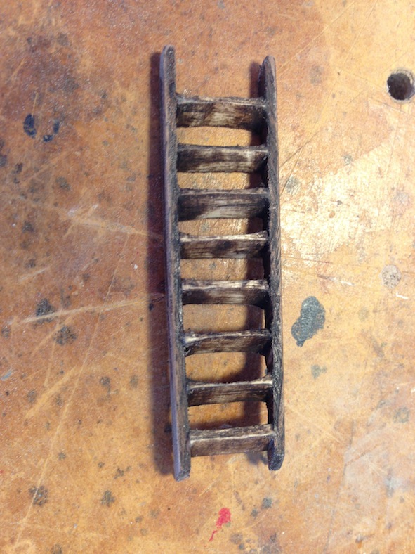
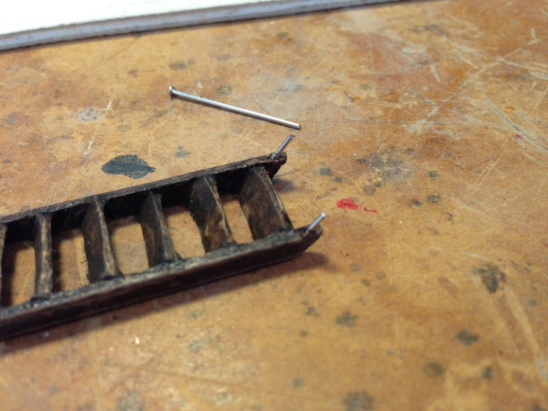
To ensure the ladders are held in place adequately, each ladder is fitted with a pin in the base. A corresponding hole is then drilled in the ship. This extra step dramatically increases the stability when the ladder is mounted between decks.
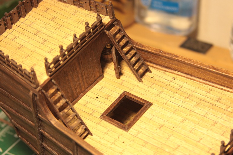
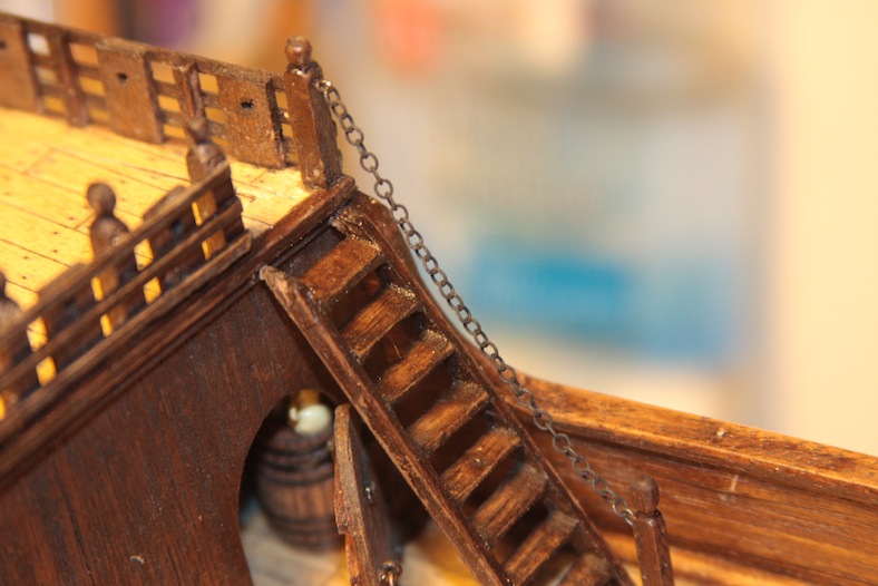
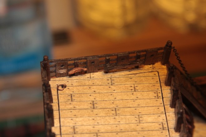
Although some reference material shows only one set of steps from the poop deck, Xavier Pastor’s reference shows two ladders. The final detail to the ladder is the chain guide running from the top stanchion to the bottom stanchion.
Although most of the research I’ve read indicates that the Santa Maria was by all accounts a very basic vessel, many of the models being manufactured and displayed have an overwhelming amount of embellishments and accouterments common to Spanish vessels. However, many of these details were not evident until decades or even centuries later. I have chosen to keep this version of the Santa Maria realistic, but I am taking some small liberties that have not been well documented. For instance, I wanted to include more decorative windows on the rear of the captain’s cabin that were likely present.
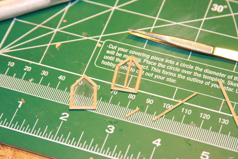
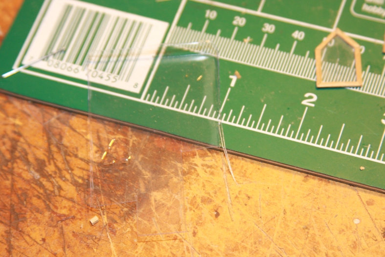
I framed the windows with 2mm X 2mm strips cut and glued. Then I covered them with “glass” made from the plastic container that held some screws. I scored the glass carefully with an older, dull Xacto blade being careful not to pierce all the way through the glass.
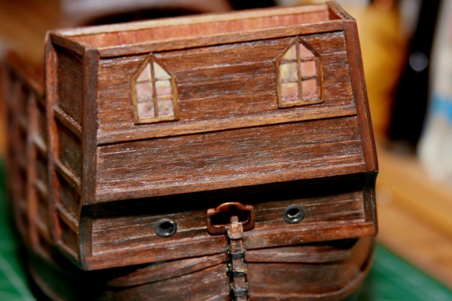
I then stained and mounted the windows to the rear of the captain’s cabin trying my best to match the coloring as closely as possible on the outside, while maintaining a mahogany color on the inside of the cabin, a location which would most likely have been more decorative.
A very tedious task that I had been putting off was the deck railings. Like the bow of the ship, the poop deck railing consists of stanchions, railings, then wooden slats.
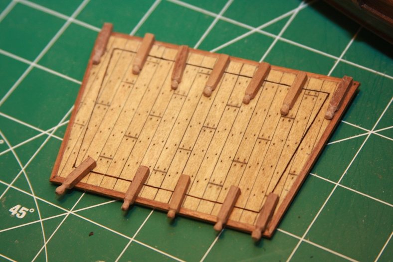
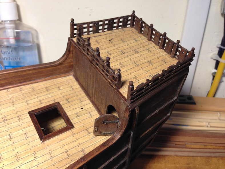
Each stanchion needs to be cut precisely then notched, rounded and sanded. Each stanchion mounted on the sides of the poop deck are the same absent the rounded top. More stanchions are then cut and prepared for the quarterdeck railings.
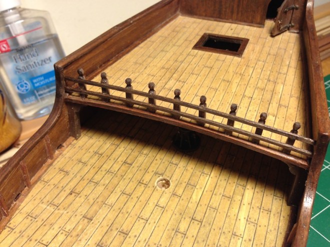
Rather than just gluing each stanchion to the deck (which would be terribly unstable), I followed the same protocol as the bow and fitted the poles with a pin to hold them in place.


