
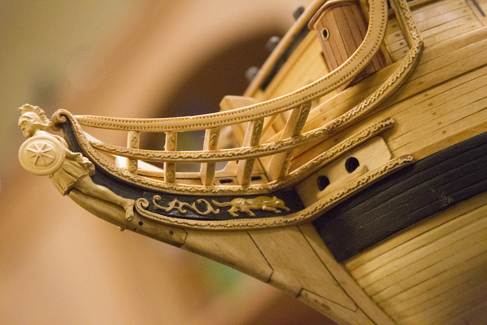
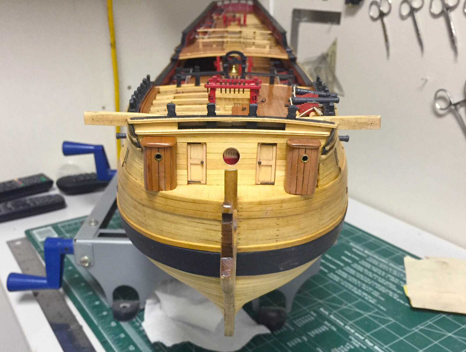
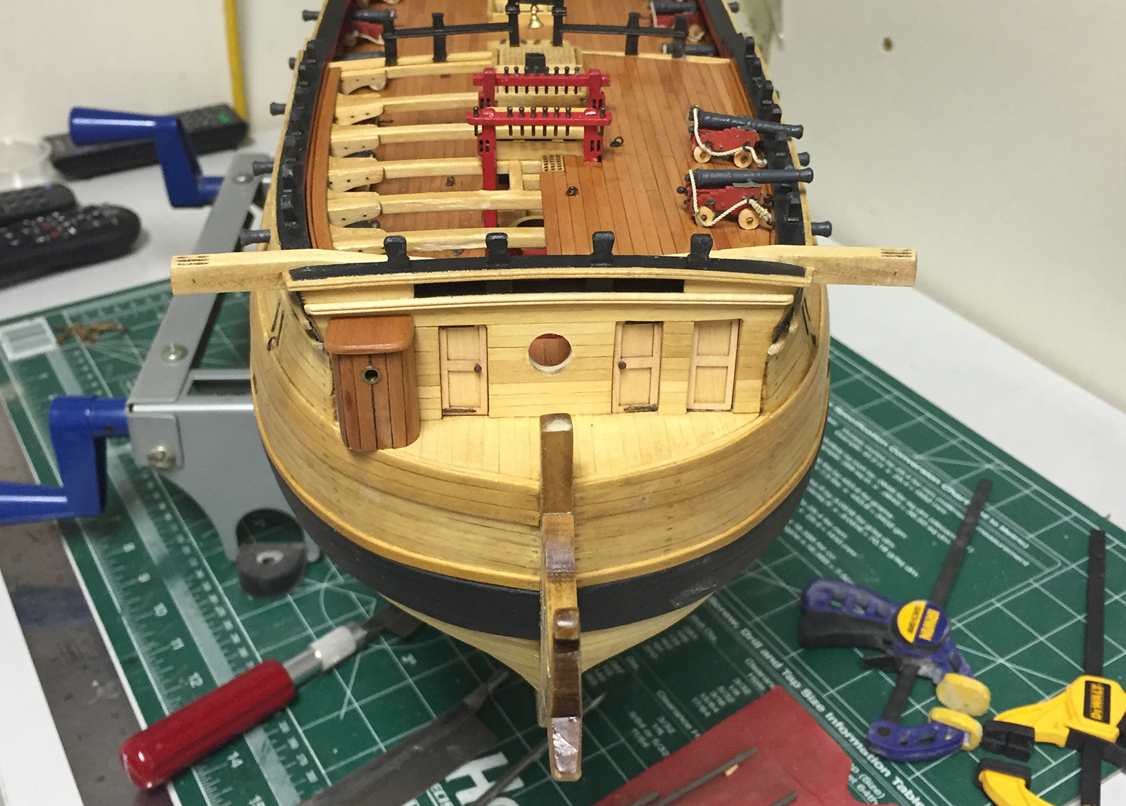
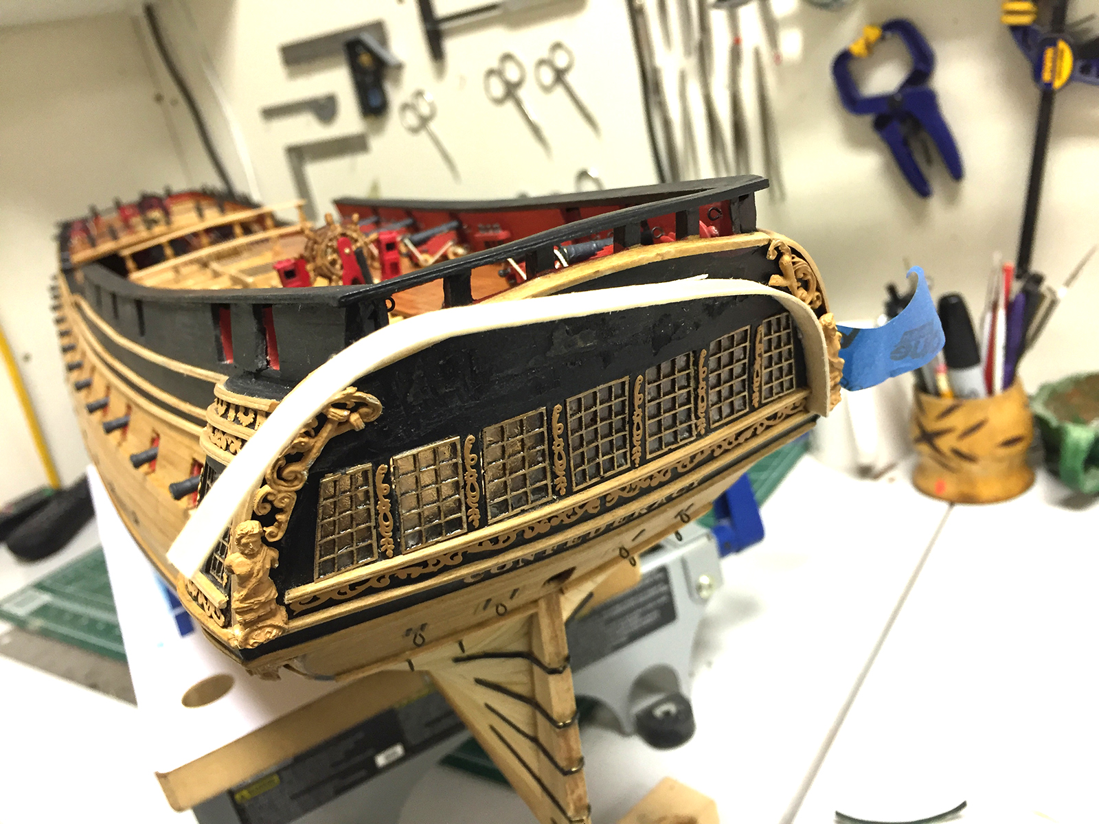
Here are the final shots of the US Frigate Confederacy – 1778.
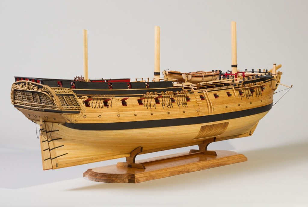


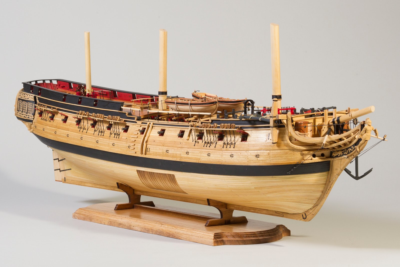


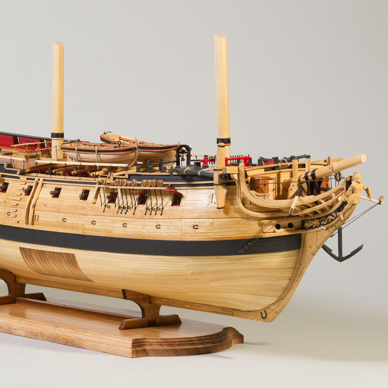
The US Frigate Confederacy launched in 1778 and patrolled the Atlantic Coast until in September of 1779 when she was called upon to transport the US Ambassador to Spain, John Jay to his post. She never made it however as she was dismasted by a hurricane three months into the voyage and diverted for repairs before returning to Philadelphia for a full refit.
Here are the final shots of the US Frigate Confederacy – 1778.
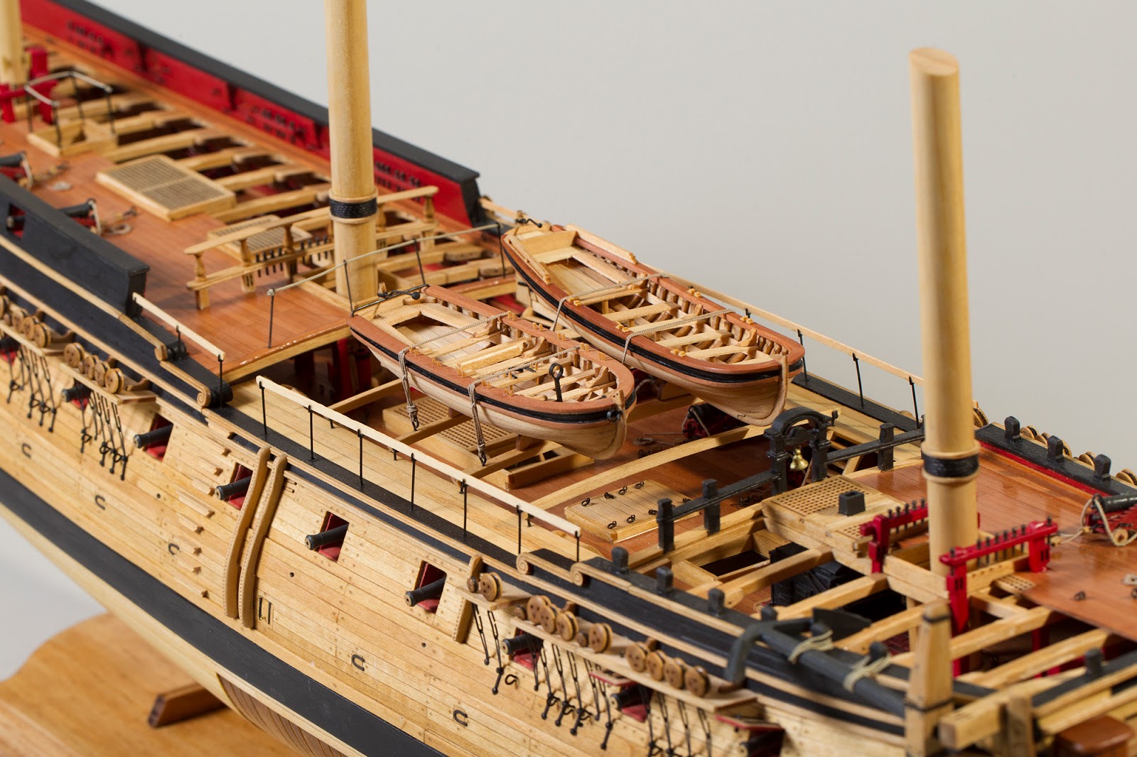
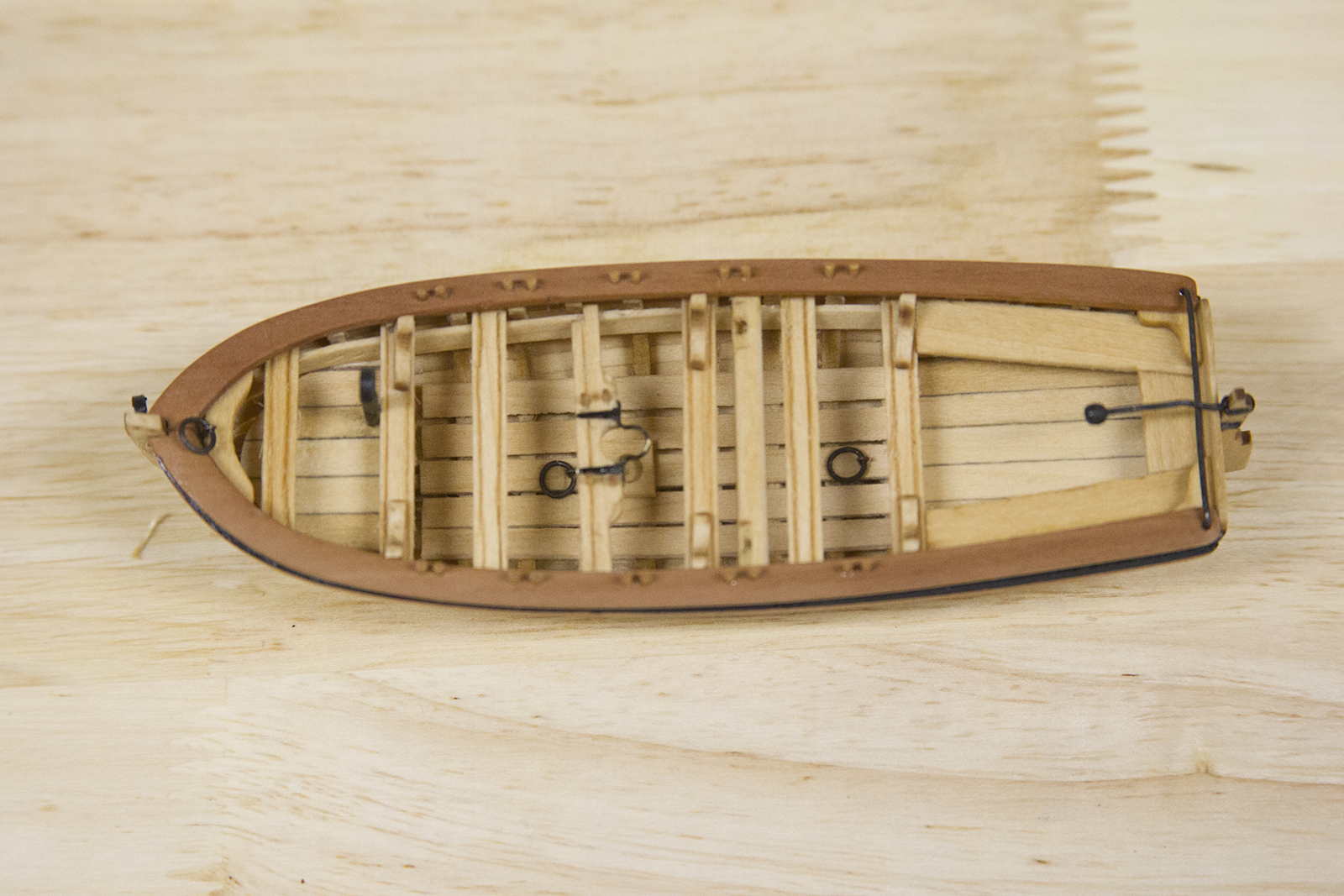
The pinnace is a 26′ launch that accompanied the longboat on the waist skid beams.
The construction of the pinnace is essentially the same as the longboat, but with a few slight differences.


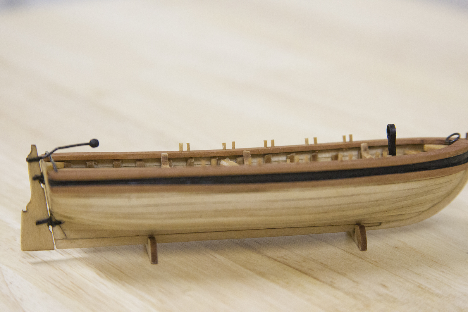
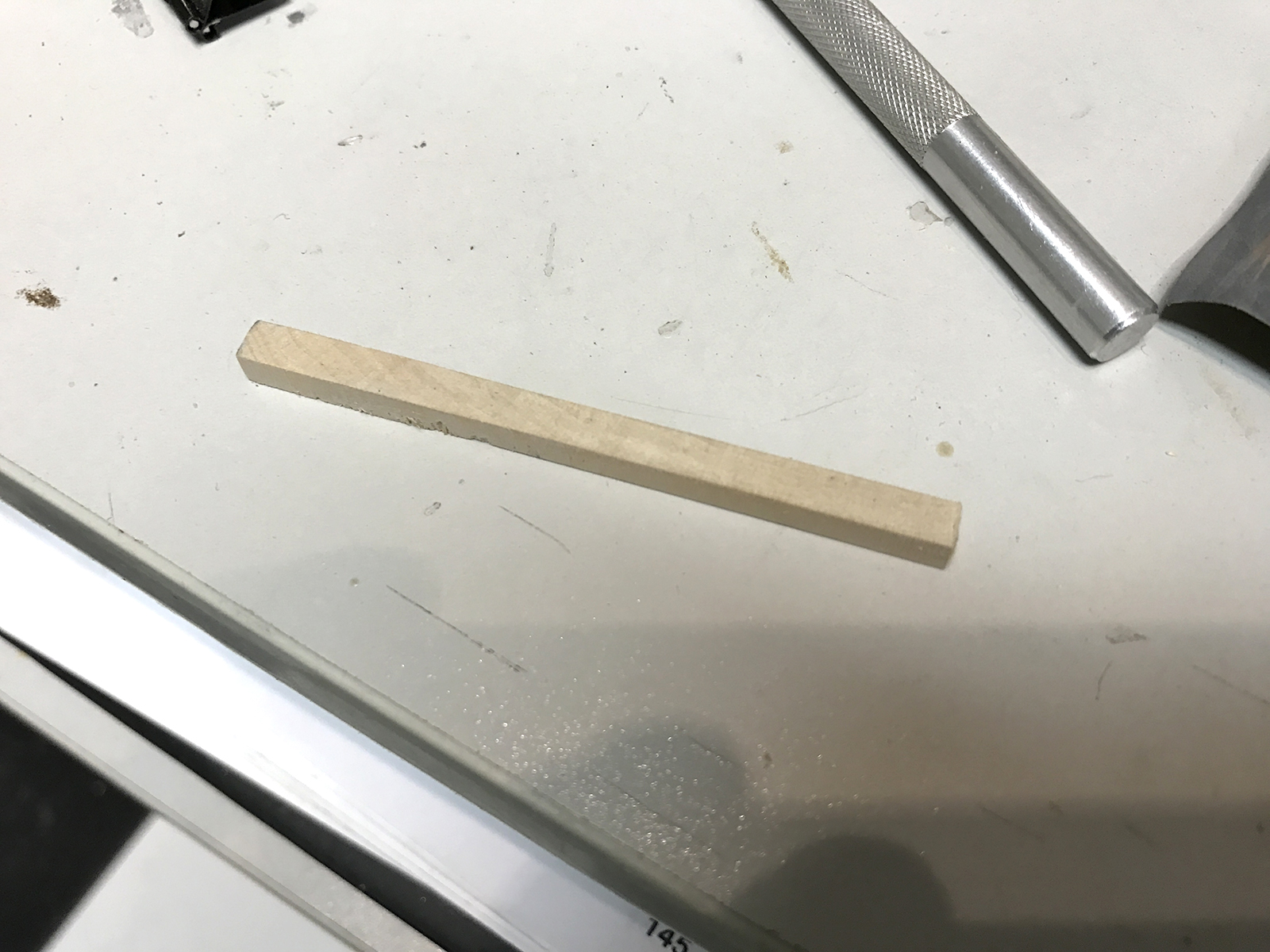
As with the longboat, I used swiss pear for the cap rail and moulding.


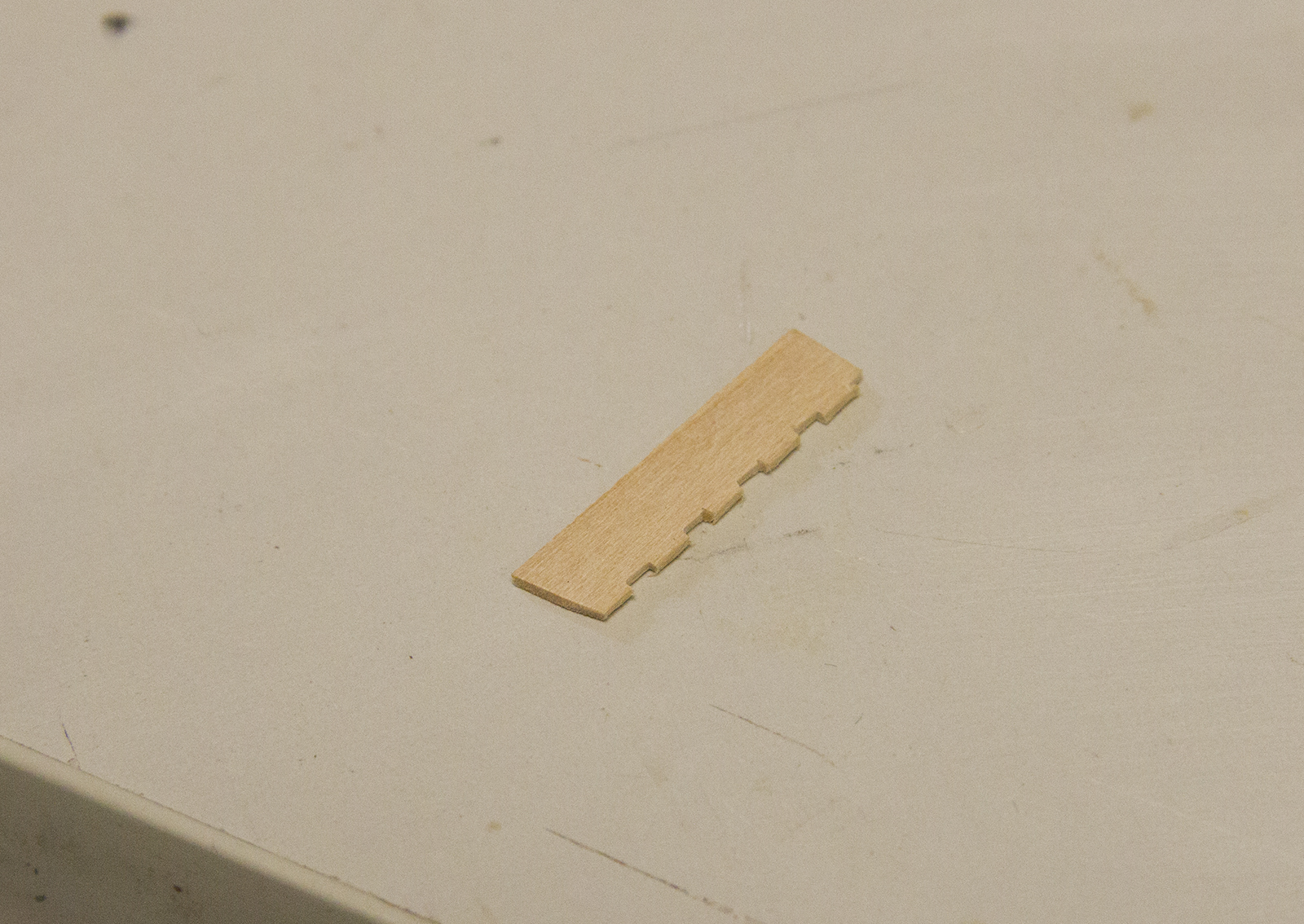
The pinnace does not have a mast, so there’s no need to form the metal rings that hold the mast or a smaller bowsprit, nor does it require a windlass. However, the pinnace does have two sets of rear seats. Each of the rear seats, as well as the middle thwarts, are all notched out to fit snugly against the frame. Then, support knees are carved out and added.

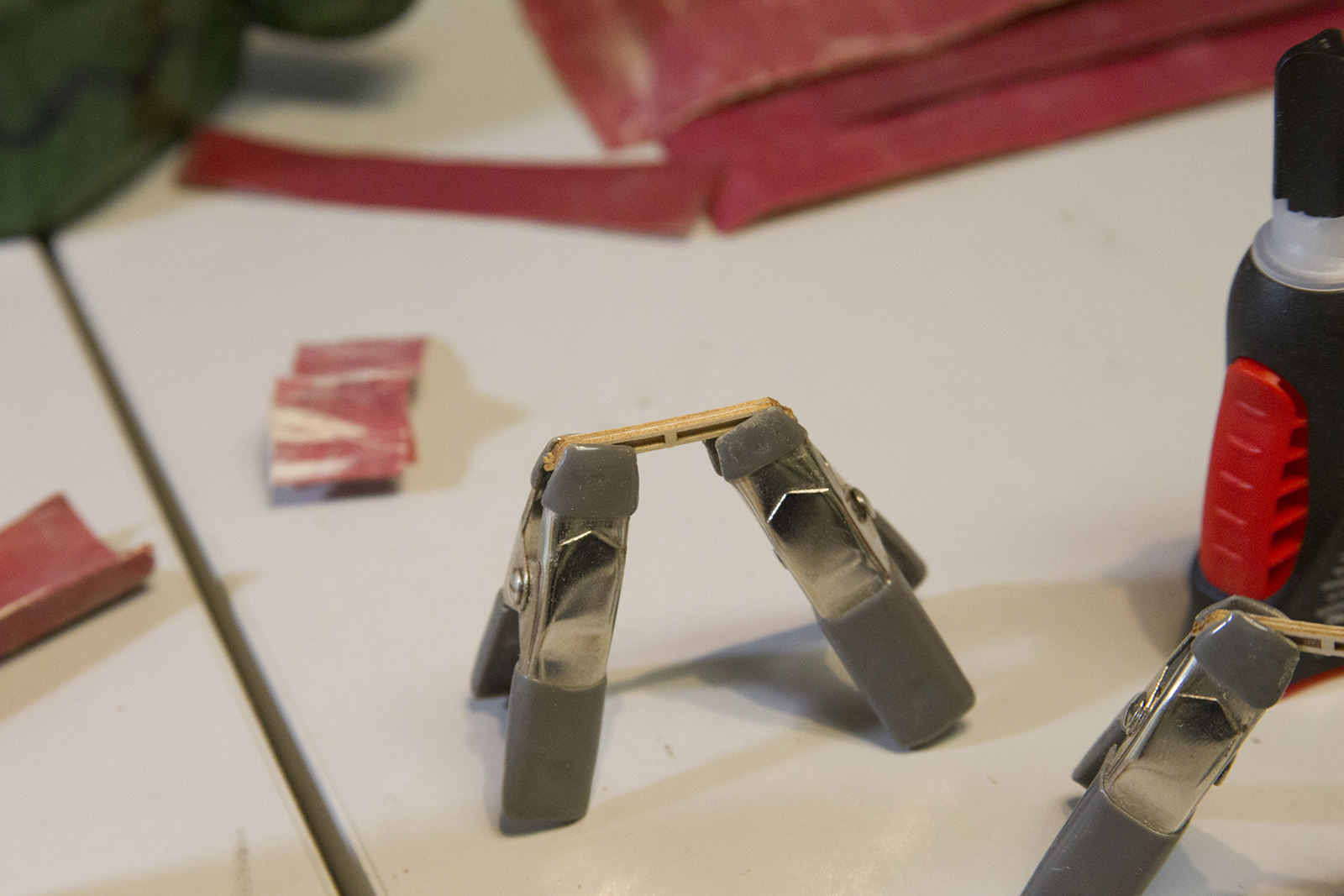
The pinnace also has rear railings. They are cut from the laser cut sheet, glued together and added.

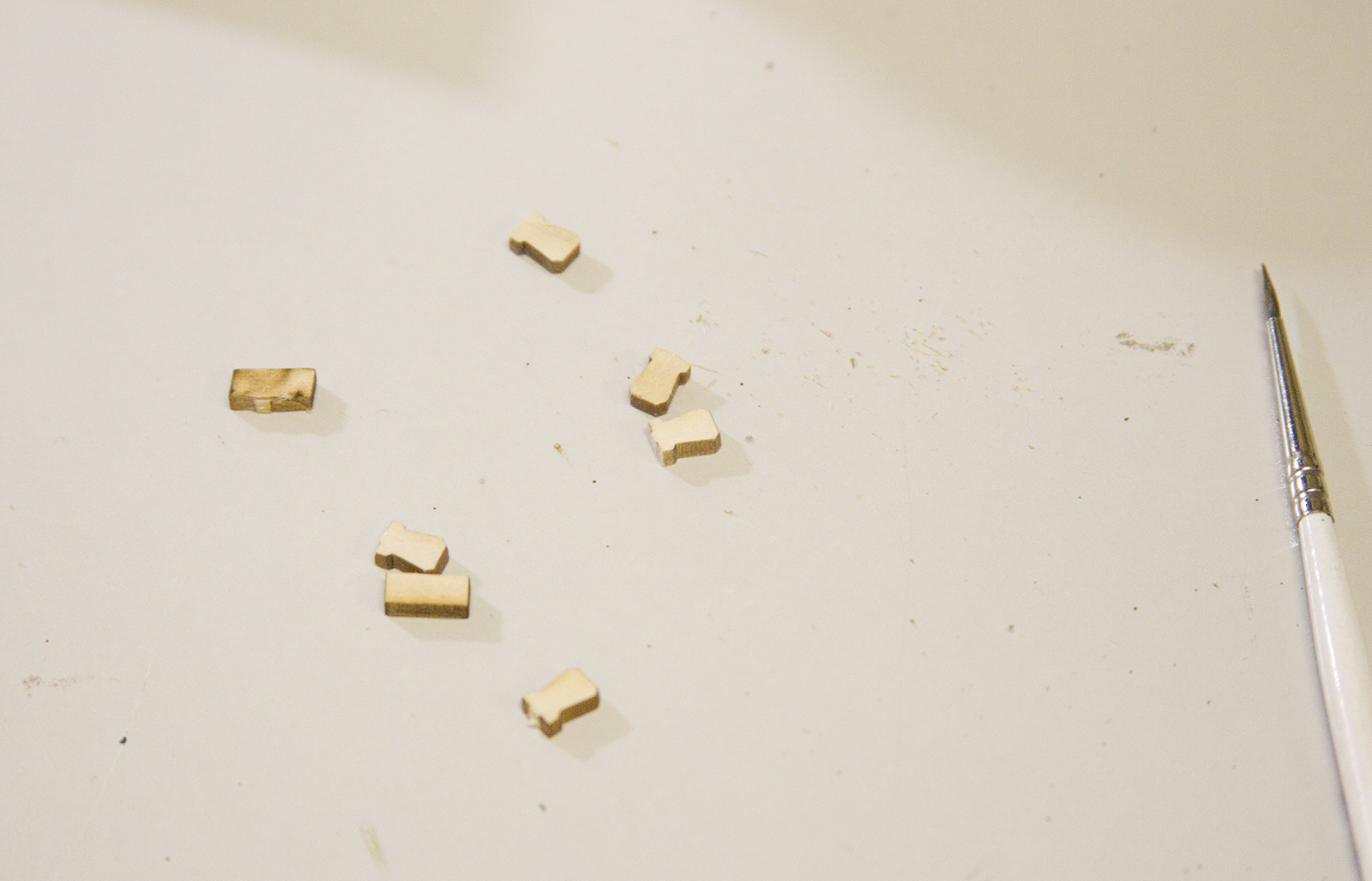
The oar locks are also different on the pinnace. I had quite a bit of difficulty carving the basswood as small as the oar locks needed to be, so I switched to boxwood which is much more dense and easier to carve at smaller sizes.

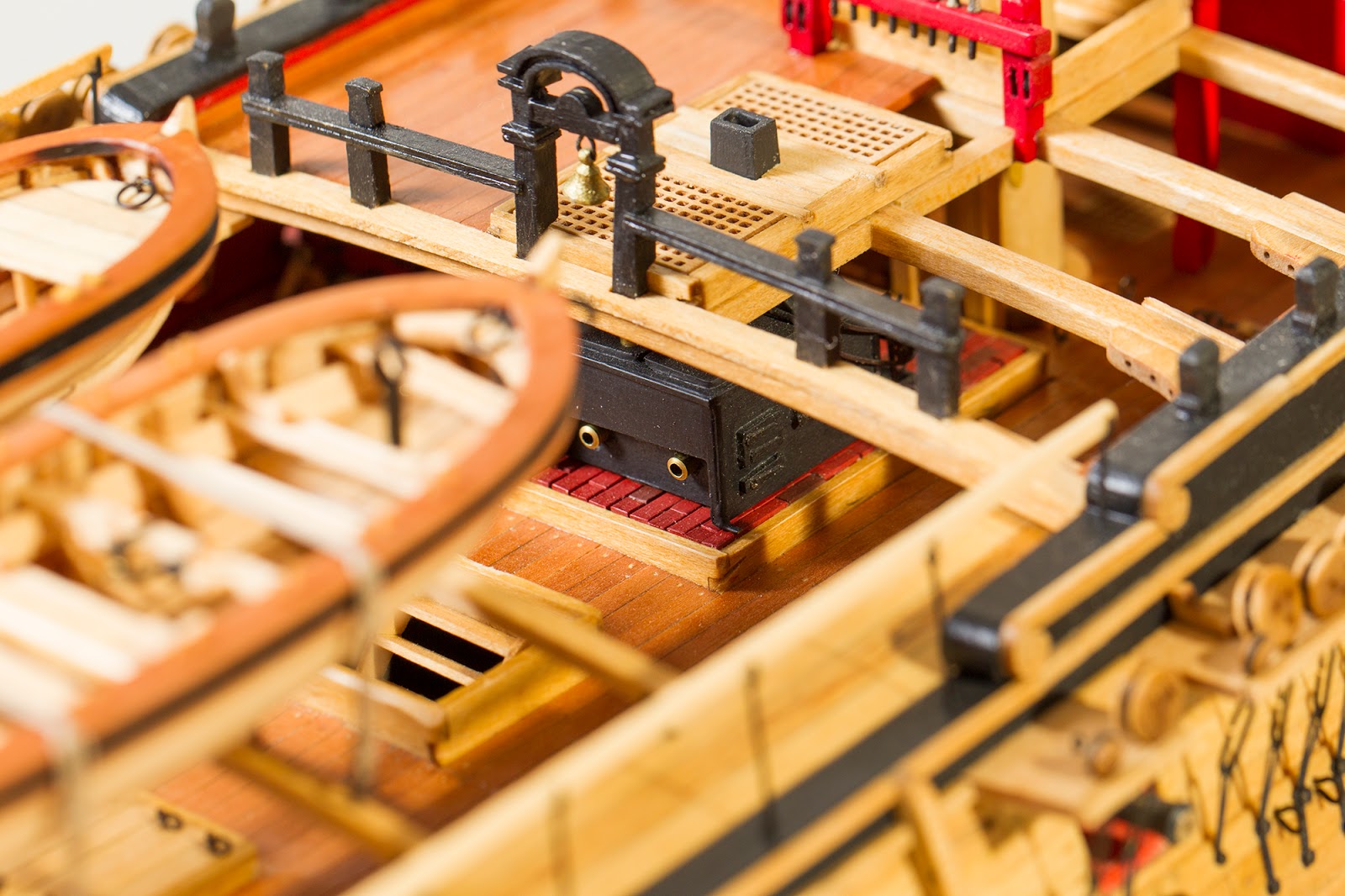
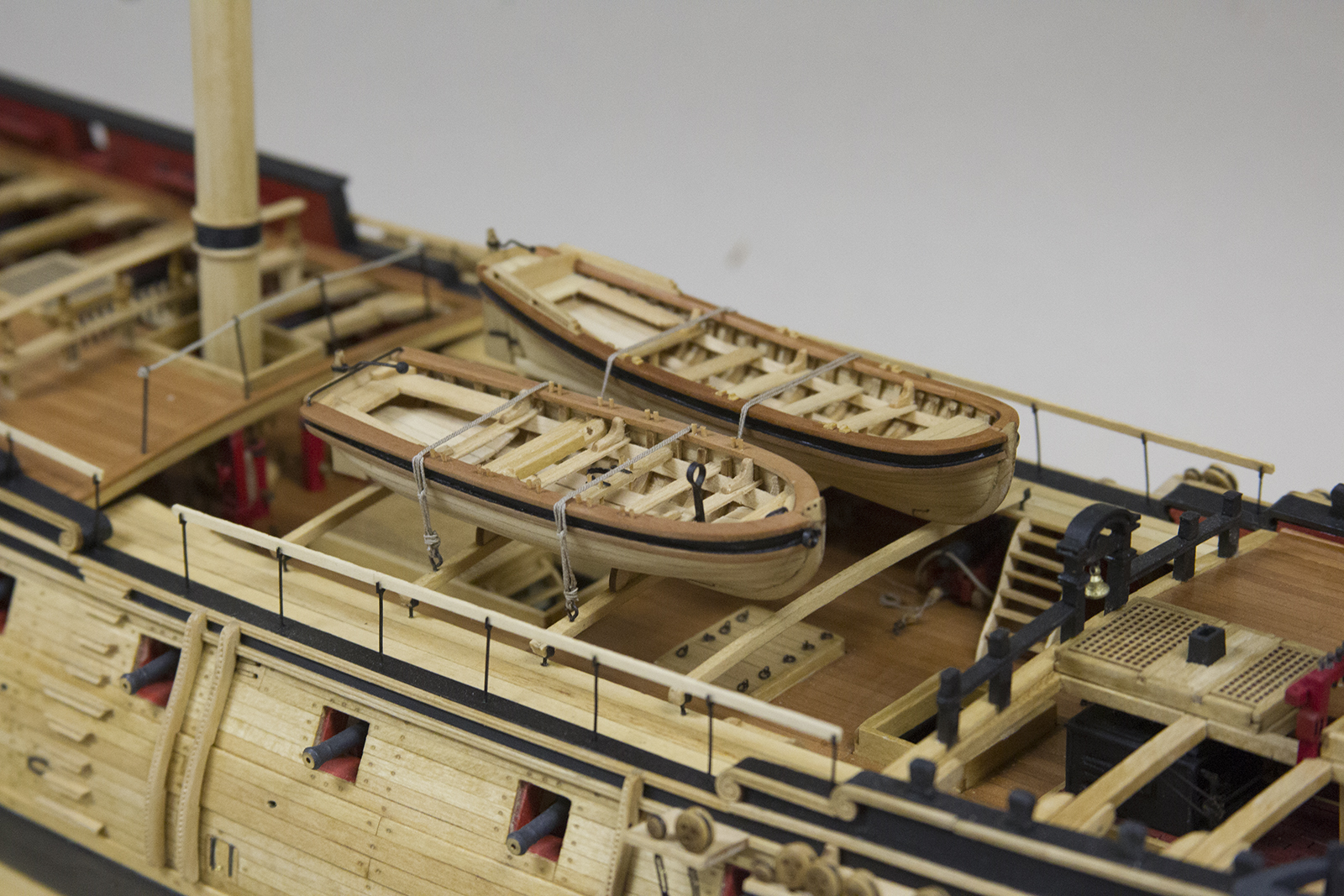
Finally, the two small boats are tethered to the skid rails in the waist of the ship. The knot I used isn’t a traditional nautical knot of any kind. Instead, it’s one of the first “slip knots” my dad taught me as a kid. We’d move around a lot – and he’d use this frequently when tying down things on our trailer so it could be easily accessed at rest areas. So, I decided to use it as a subtle homage to my late father.

And with that… all that remains are the final photos of the Confederacy.
The USF Confederacy most likely had a minimum of four smaller boats secured on board. However, the model representation will have just two small boats mounted on the skid beams across her waist. There will be a 22′ longboat, and a 26′ pinnace.
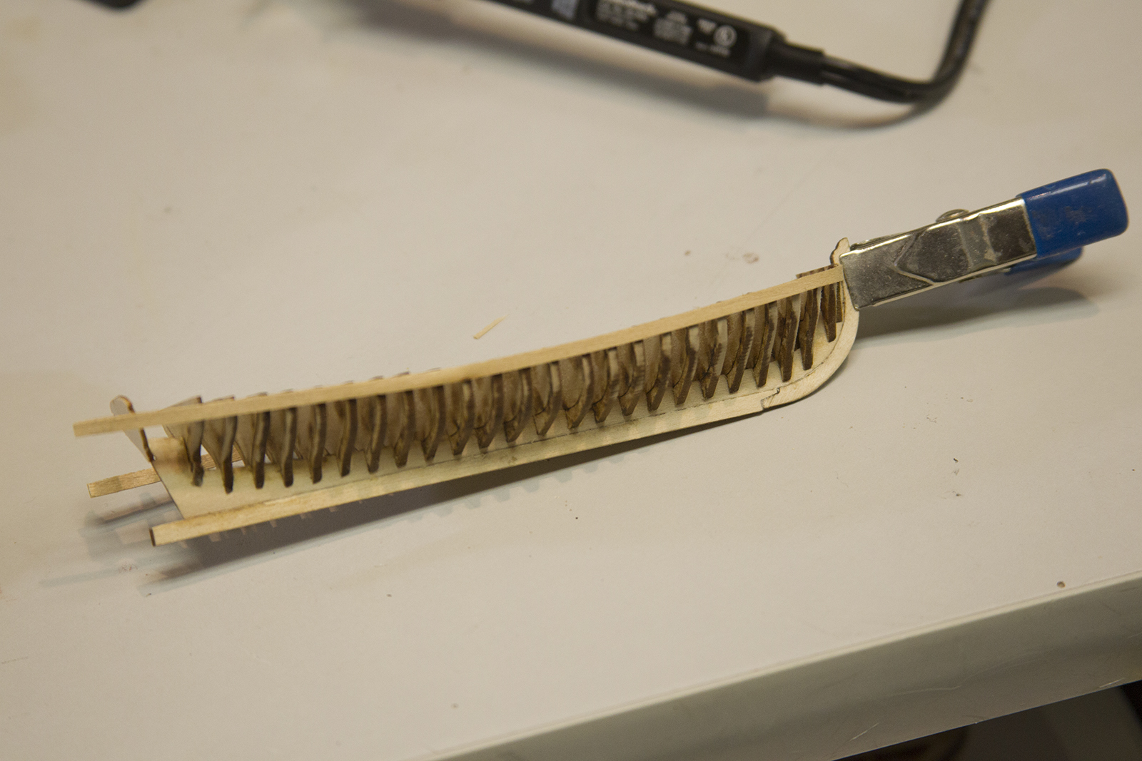
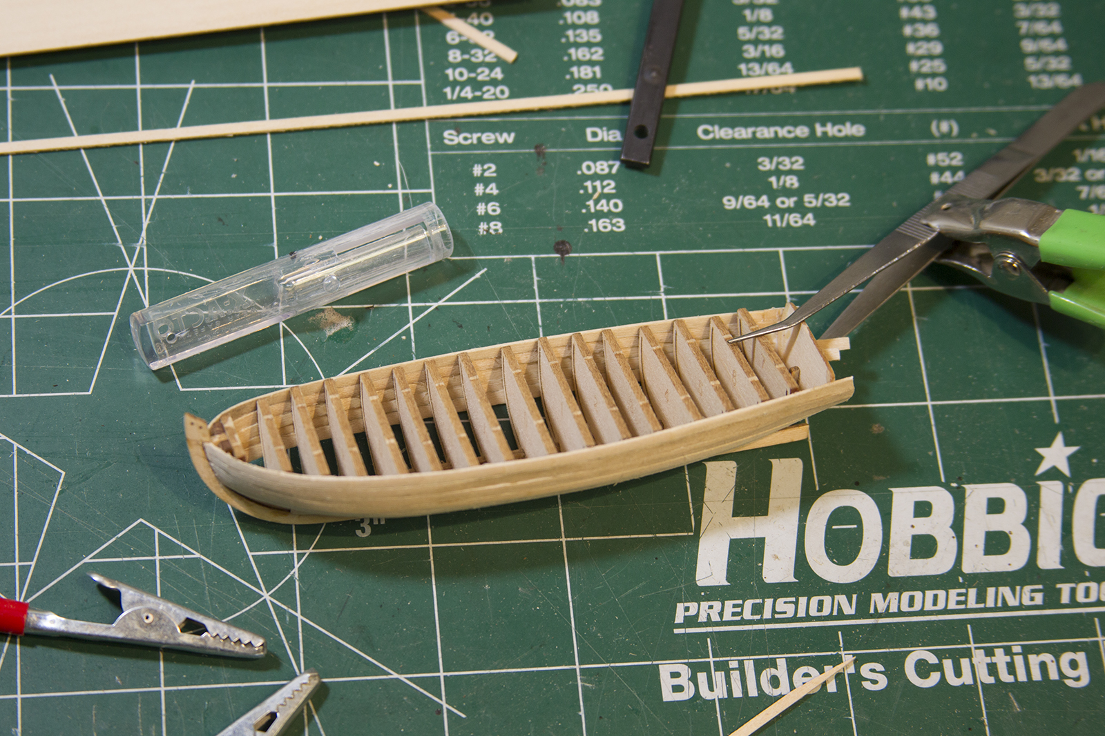
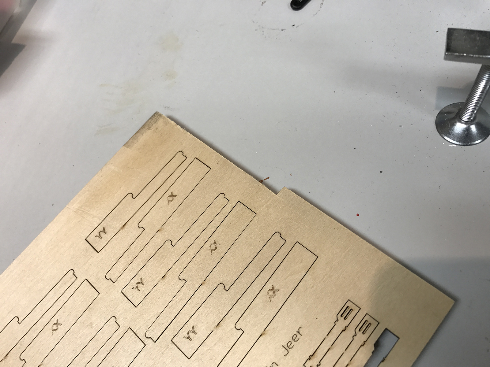
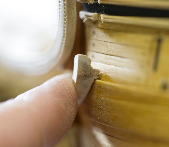
This post represents at least couple of weeks of work. Because it’s obviously slow-going, I started on the small boats at the same time as the anchors and other details and worked through them simultaneously. I will say – I was quite pleased with how the small boasts are laser cut and put together. Each keel, false keel keel and bulkhead are laser cut on a sheet of parts. The good news is, there are plenty of extra parts available on the sheets. This is good because the parts are all very delicate and I’ve snapped off and had to recreate quite a few along the way.
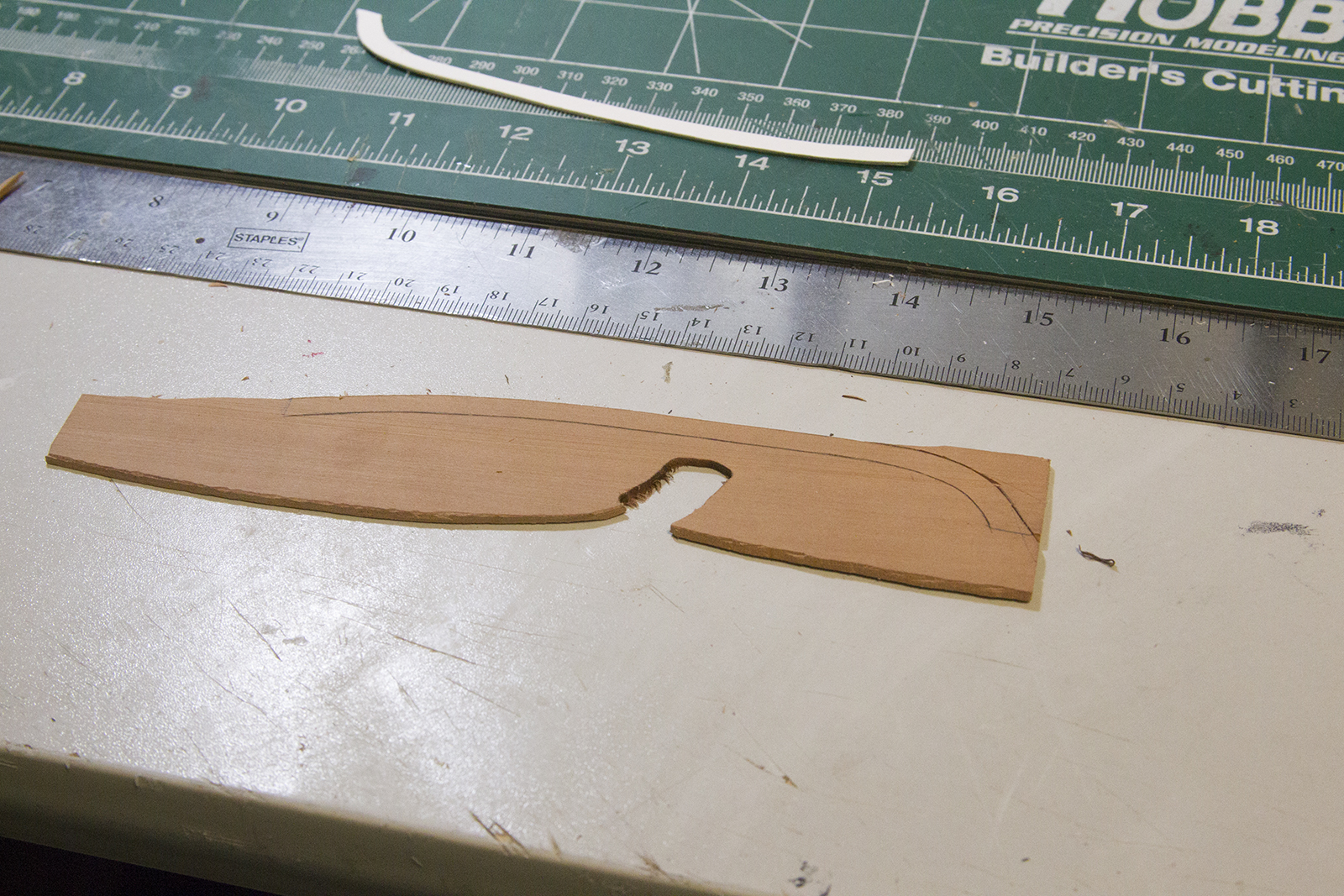
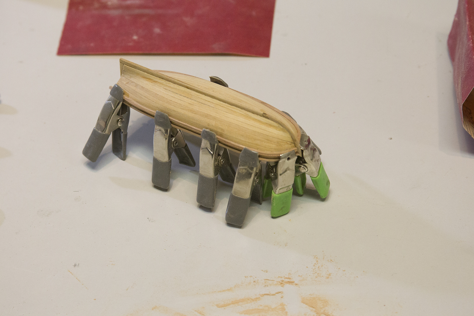
Each small boat is facilitated by a “plank on bulkhead” type framing just as the larger ship is built. However, the center of each bulkhead is then removed, just revealing the inside framing. I’ve always struggled with coming up with small boat bulwarks, and inevitably end up with uneven hulls. Don’t get me wrong – I still came up with uneven hulls – but at least they were closer than I’ve been able to do before. I’ve constructed a few of these small boats, and this is by far the easiest method that I’ve come across thus far.

Although I initially started with both boats – I ultimately finished off the longboat first before moving on to the pinnace. It’s a bit tricky to get each bulkhead lined up on the keep properly with the same amount of space along the framing. As a result, I ended up using CA glue (superglue) throughout the process.
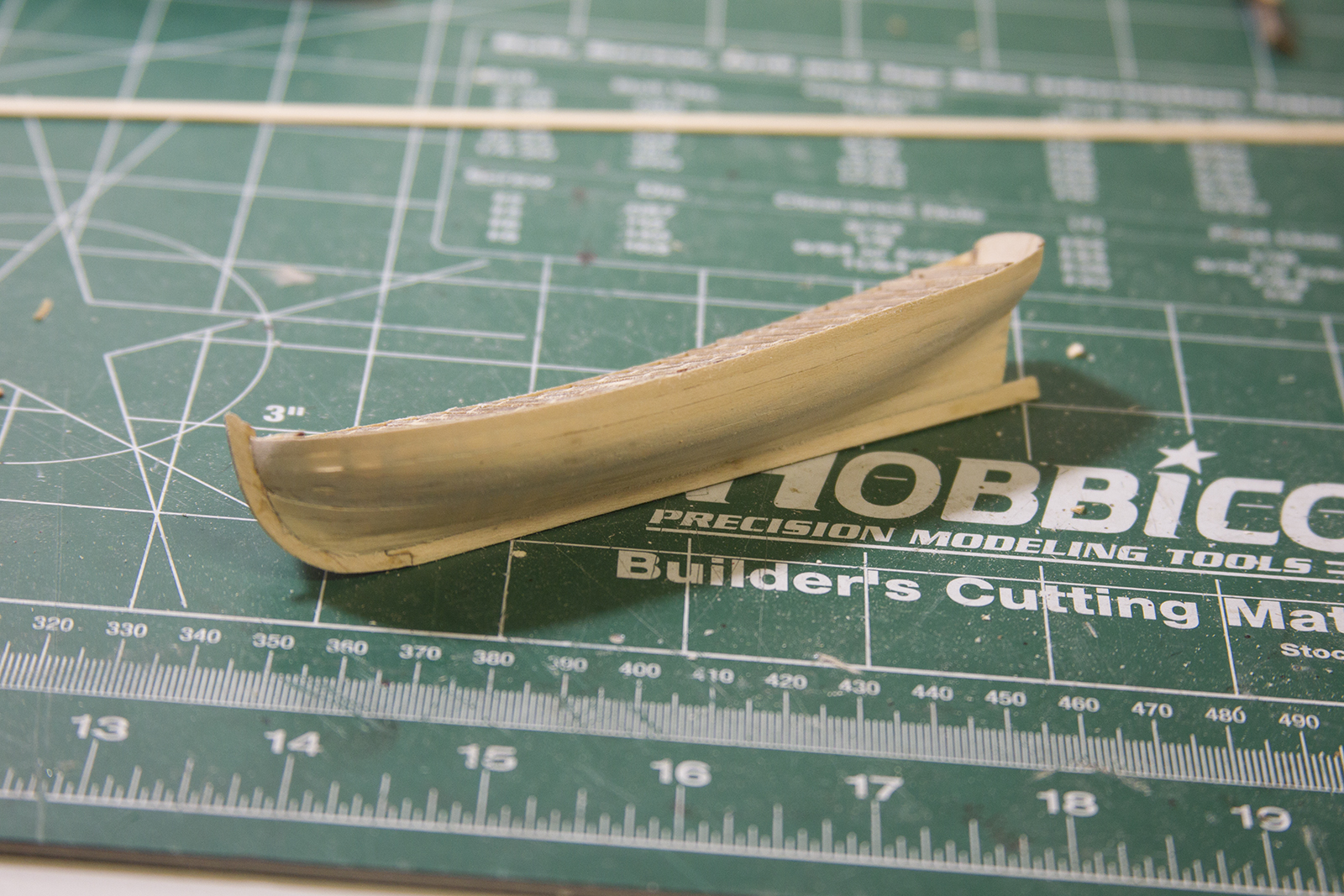
After the bulwarks are in the place, the planking begins. As with the larger boat, this is a slow and repetitive process. Each basswood strip is measure, cut, soaked, bent with a heat source, then mounted. As there is only one layer of planking here, one must be quite careful because there isn’t much room for error – the planks are very thin and only a limited amount of sanding can be performed. In fact, you will notice in the some of the shots (with light behind the boat) how thin some of the areas became as they were evened out.
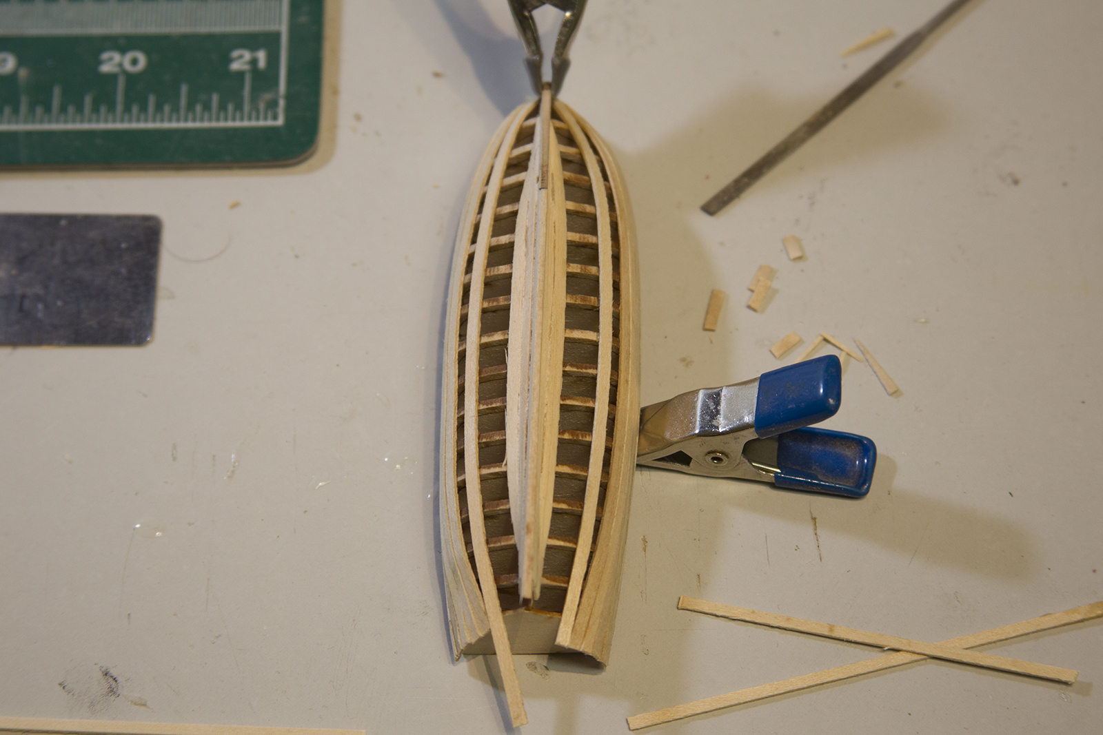

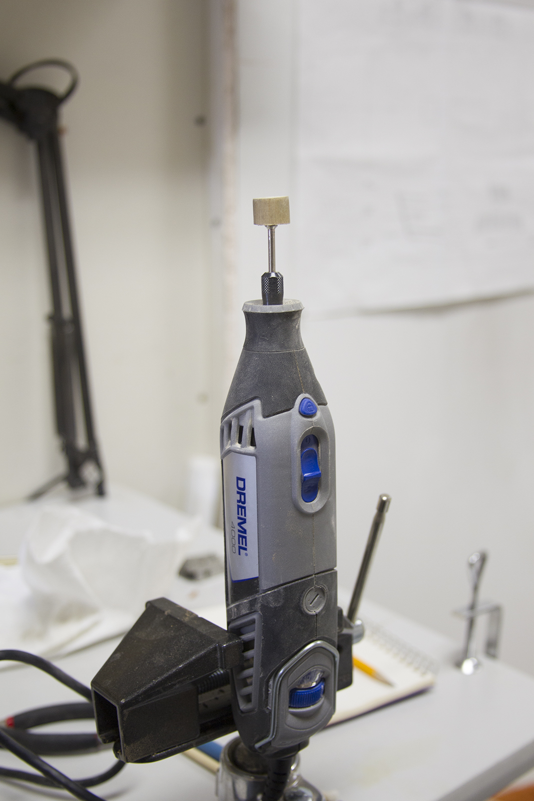
After the longboat is planked, it was time to pull out the bulwark centers. MAN what a sketchy job that was. I tried ‘filing’ off the edges (*as recommended in the instructions) with my smallest needle file, and that was a pretty quick failure. Then I sliced a tiny bit at a time using a super sharp X-acto knife. A little bit more success, but still difficult. It took about two thousand delicate slices to get through. So finally, I put a super thin blade on my Dremel, put it on it’s highest speed, and cut through the edges. No matter what method I used, I inevitably snapped off at least a few of the frames and had to re-glue the tips back on. Then, sanding the frames inside and evening out all of them was a very slow, tedious process as well.
My solution for that was a very fine sand attachment on the dremel that had a rounded cone-shaped and some very careful sanding.
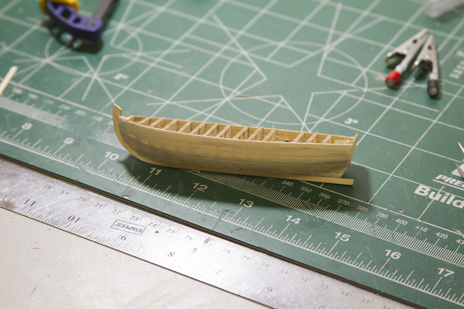
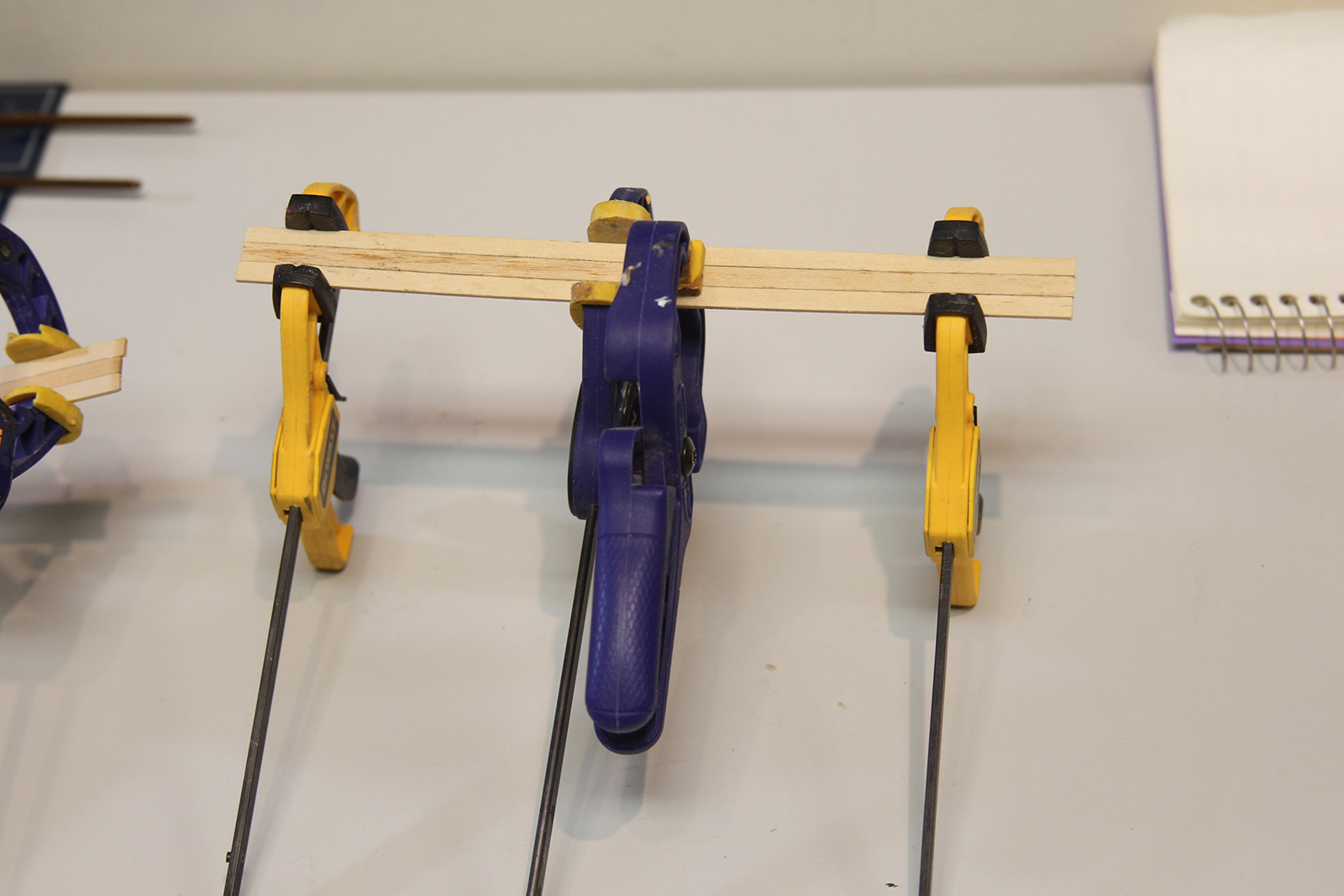
In keeping with my earlier idea to bring the center of the ship together artistically with the deck, I used Swiss Pear for the cap rail and moulding – the same wood used to plank all the decks of the ship. Obviously, the Swiss Pear is about a million times more dense than the stock basswood, so I had a number of failures.
Honestly, I blame them on impatience. I outlined the cap rail then tried to use a Dremel attachment and some other ideas to cut through the Swiss Pear quicker. Just like we always seem to learn – it ultimately takes longer trying to come up with a “short-cut” than it does just to be patient. The solution here – draw out a template onto the Swiss Pear, and cut with a sharp blade. Sure, you have to go over the cut about 50 times to get through the dense wood, but it’s worth it in the end. Then it’s all about sanding and matching.


Moving on to the inboard details. Most of these things are pretty straightforward. The floorboards are strips of basswood measured and glued in making sure there is enough space between for drainage. The seats are strips of basswood planked together with “caulking” in between simulated with pencil lead. I just planked six or seven strips together at about 6 inches long so I’d have enough wood to work with for both small boats.

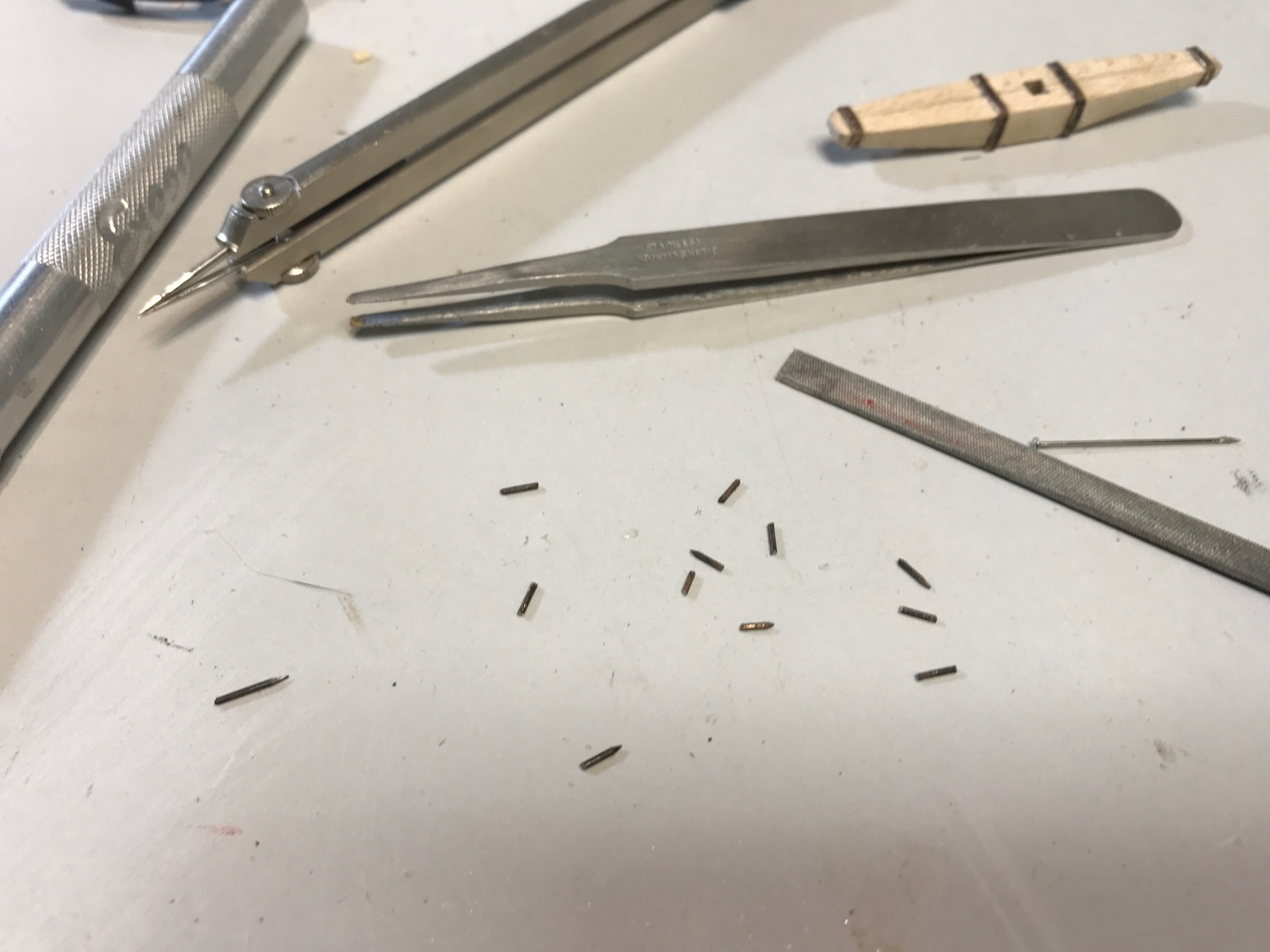
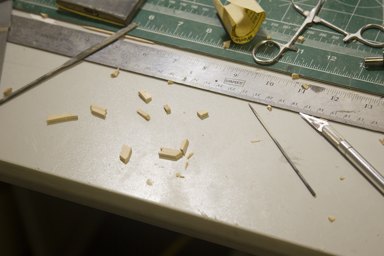
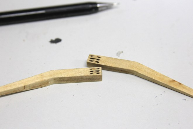
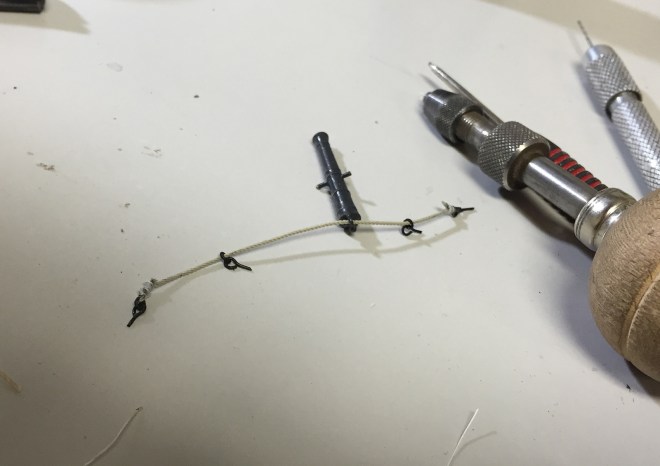
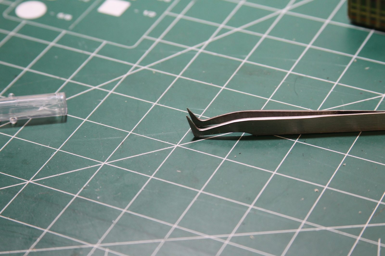
The risers (two strip along to side) are added as well as the “thwarts” or seats. Each of the seats is measured and ‘scored’ with a gouge along the edge. It was pretty tricky getting a good score along the edges of the seats. I wish I’d have taken a picture of it, but my method was to pinch sharp tweezers (you can actually see the tweezers I used in the photo below) together with a small piece of wood between them to keep the ends a consistent distance apart. Then I dragged one tip along the outside of the strip of I wanted to score as a guide – while using the other tip to score the wood.

One seat is slightly wider, and is home to the mast hole as well as four belaying pins for rigging the small sail. To create the belaying pins (and oar locks later) I used the same method as “trenailing” the hull or deck. I sanded down an already small diameter dowel, then inserted it into predrilled holes.
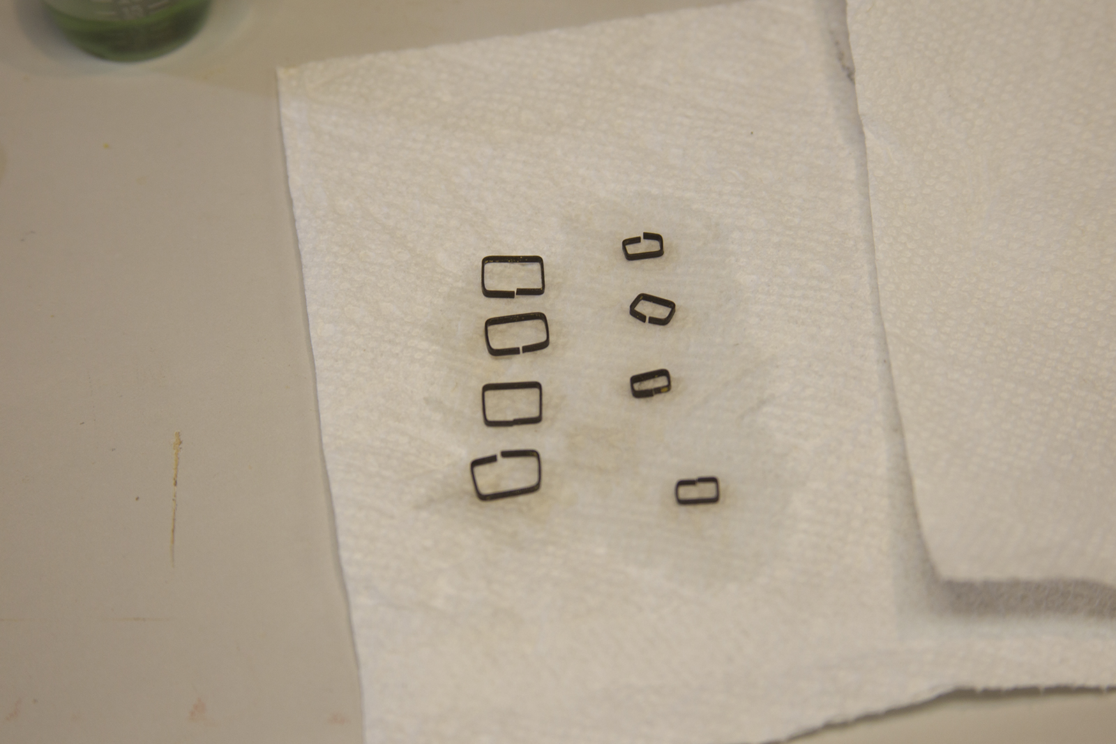
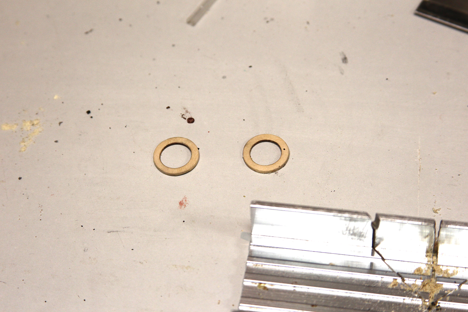
The rear seats, knees (small braces along the inboard hull and frame), and windlass are added to the boat. The rigging rings that were used to mount and unmount the ship are also added after being put together and blackened. The two rings on the front seat and bow of the ship are bowsprit rings – folded strips of brass that are moulded around a dowel to create a ring, then glued together and inserted into the boat.
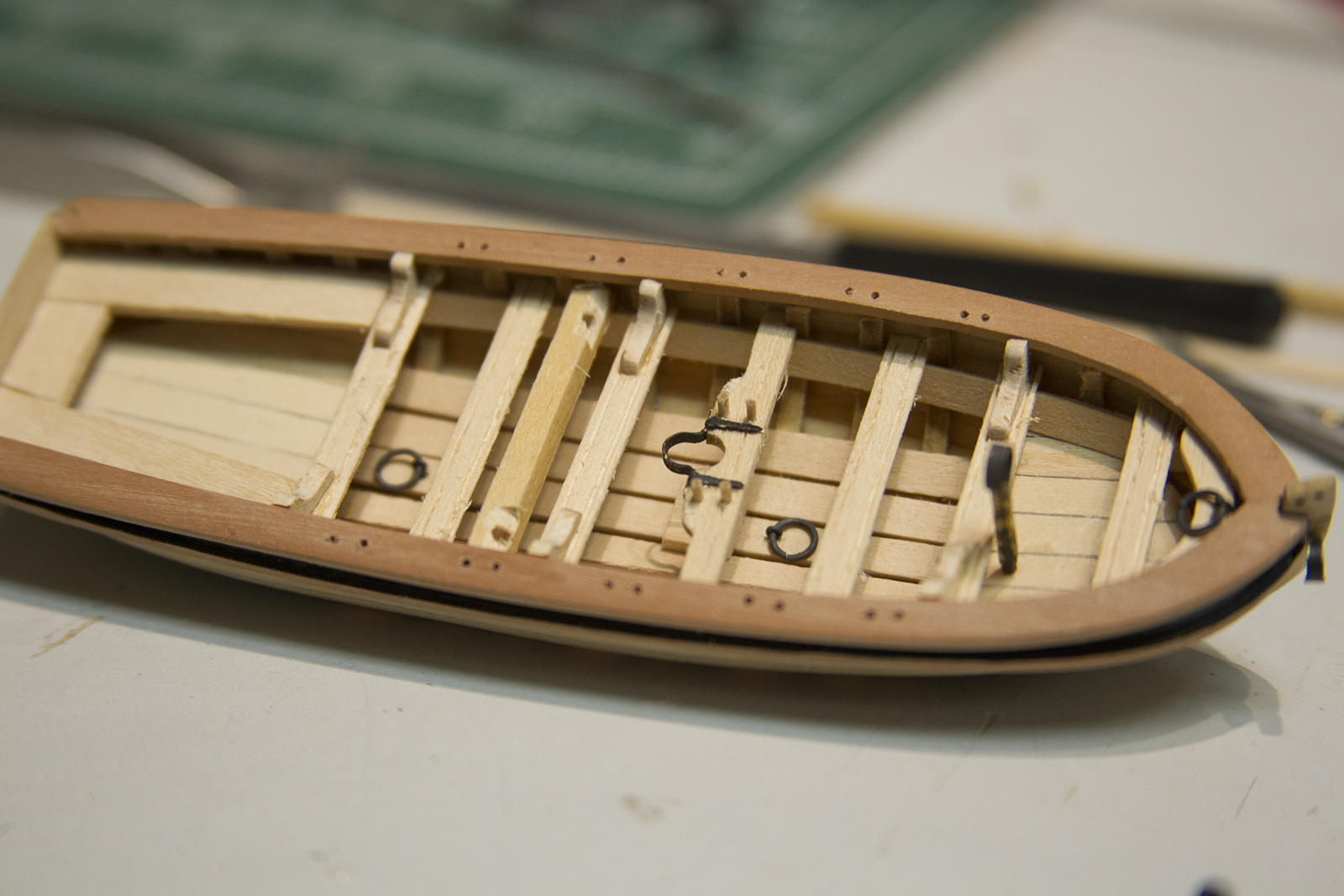

As I mentioned – the oar locks are added the same way as the belaying pins and trenailing a hull. I gently sanded down a dowel by mounting it in my Dremel as a makeshift lathe, then glued the end into each hole in the cap rail and snipped it off. The instructions call for these to be made out of wire then painted to match the wood. However, my primary reason for using a dowel instead – is my general inability to properly match paint to the wood color that the basswood ends up being after it’s stained. I do also feel as though the natural looking wood does look a bit better than paint would as well.


Finally, the rudder is added and mounted with more blackened strips of wood. A couple of the final steps include the rudder handle as well as a traveler bar at the rear of the ship – both constructed with 22 gauge black wire.


I’ve been working a little bit of double duty as I get closer to the finish of the Confederacy. I’ve started the ships boats, but have also been working on anchors and small details of the ship.
Nothing particularly complicated with the anchors. As with most of the laser cut parts, the anchor stocks are pretty beefy and required a fair amount of sanding. I used pin files to notch them of course, but the wood itself is soft, so I used nothing grittier than 400 grain sandpaper to ease them down bit by bit and bevel them.


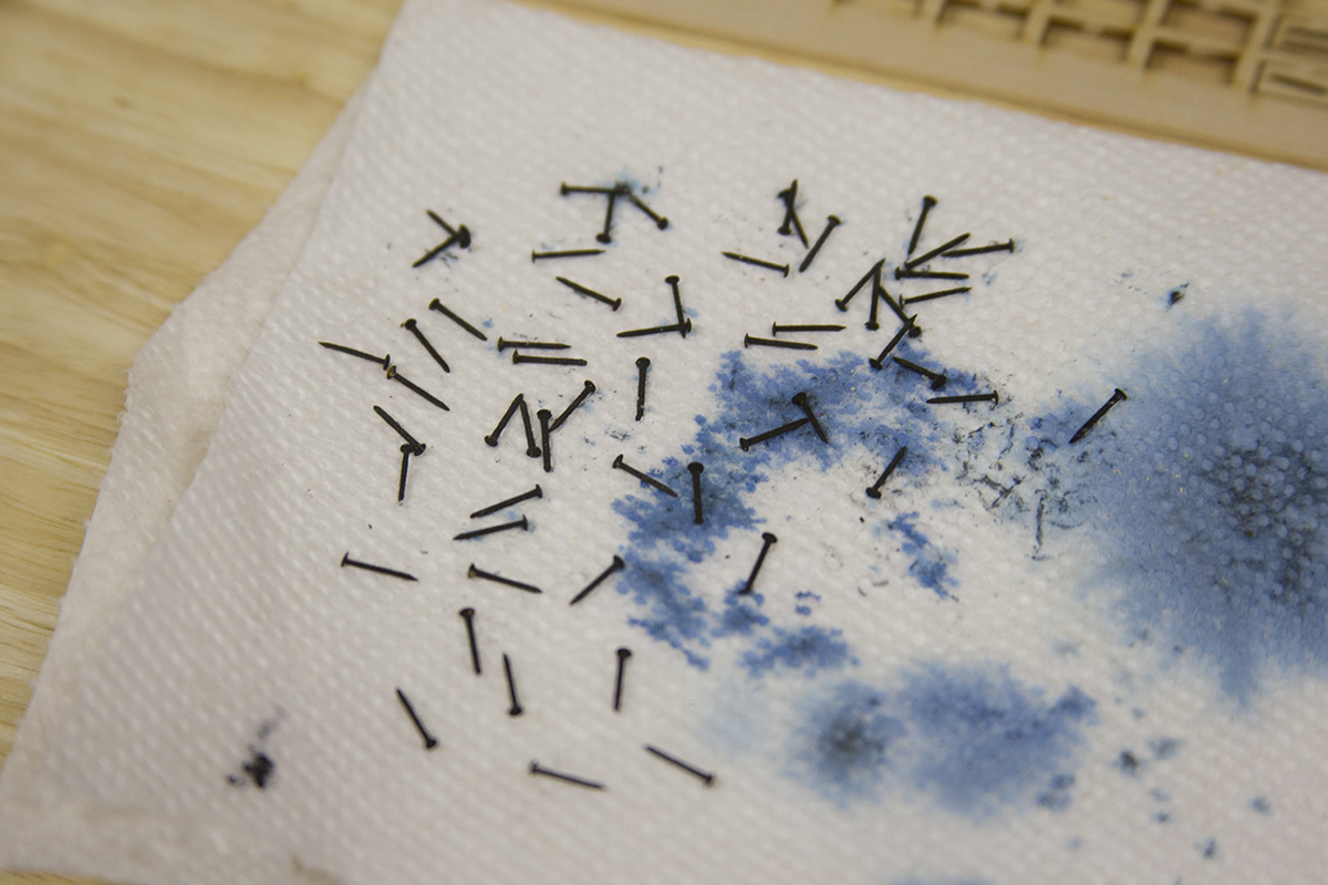
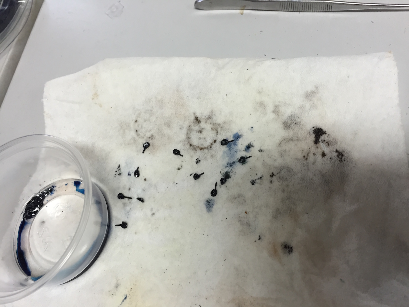
The anchors themselves are made from a die-cast soft metal – essentially pewter. Everything is sanded and fitted. The anchor stocks are then glued together and secured with pins. Each pin is a cut nail that’s sanded down clean, then blackened.

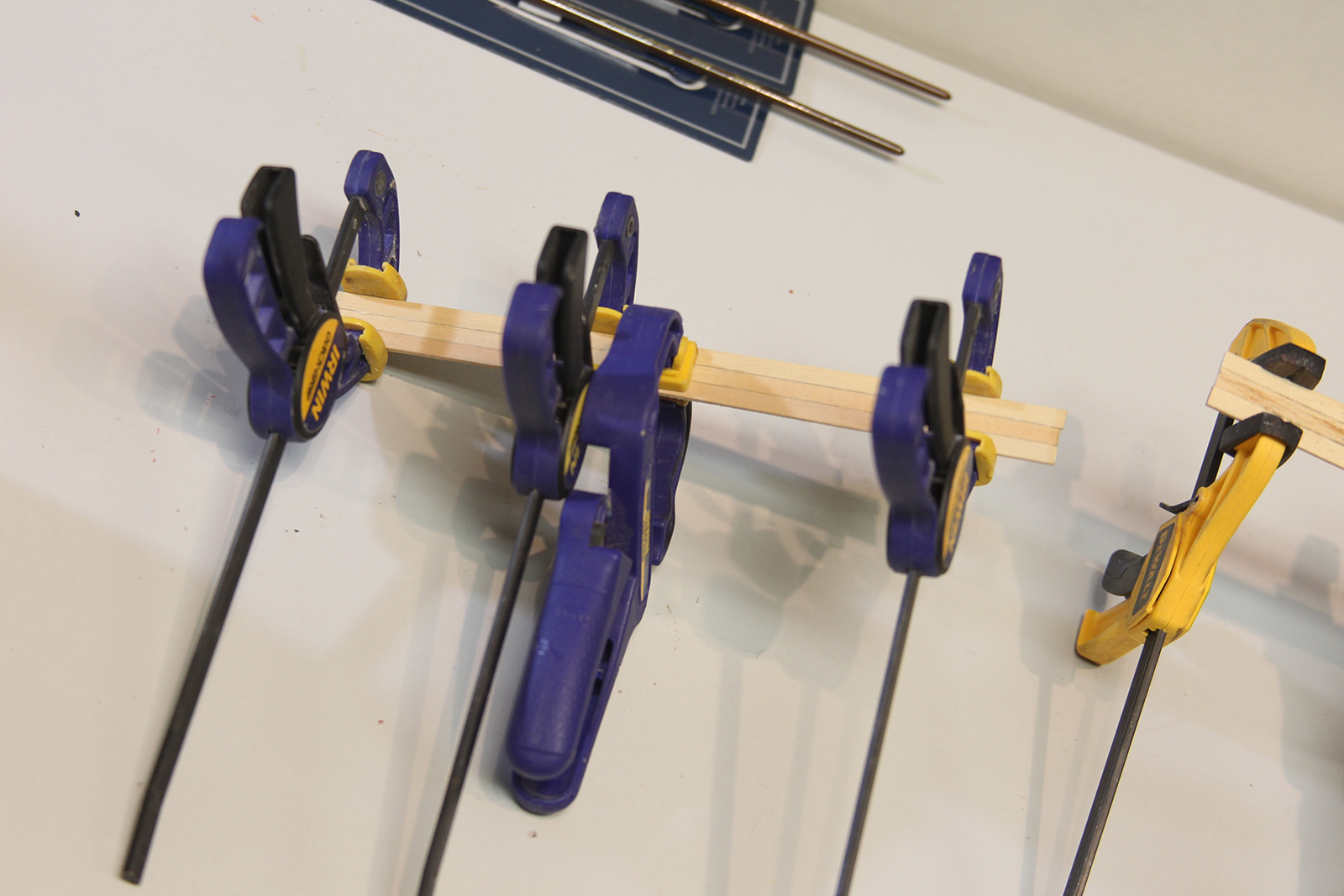
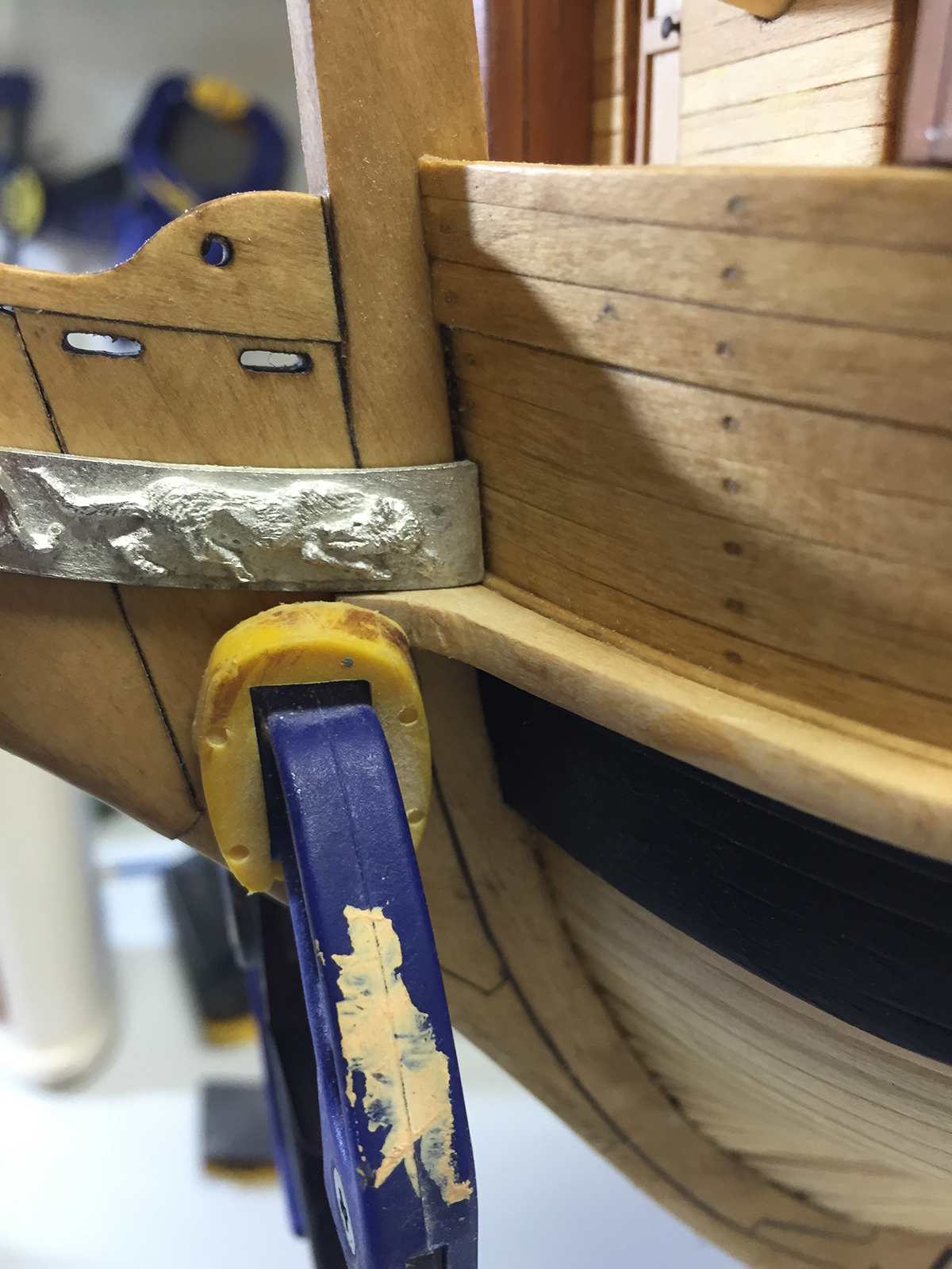
Once again – the recommendation for the bands is thick card stock. Instead, I increased the authenticity by using brass strips that are measured and blackened. Each strip is pretty difficult to glue in place and needs to be clamped securely.
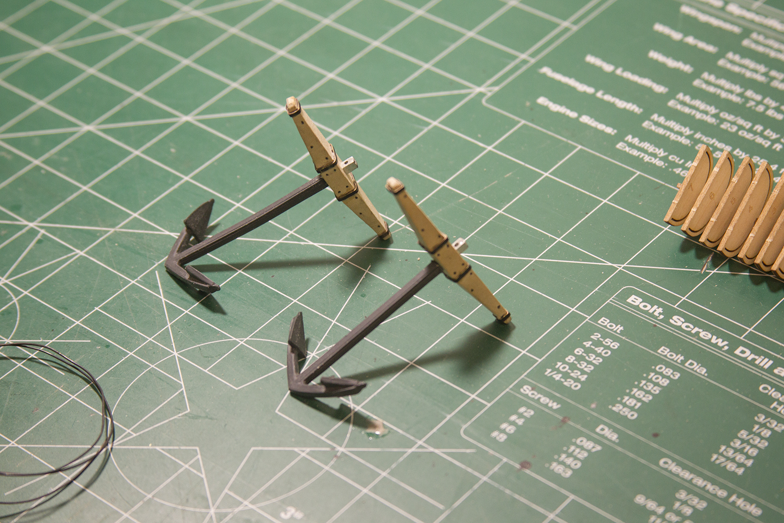
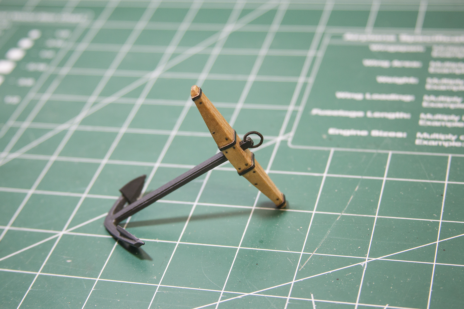
The final step is ‘serving’ the anchor ring by wrapping it in small black rigging. The ring is then mounted to the anchor above the blocks. Once all together, the anchor stocks are stained with a coat of conditioner then natural stain to match the hull of the ship itself.
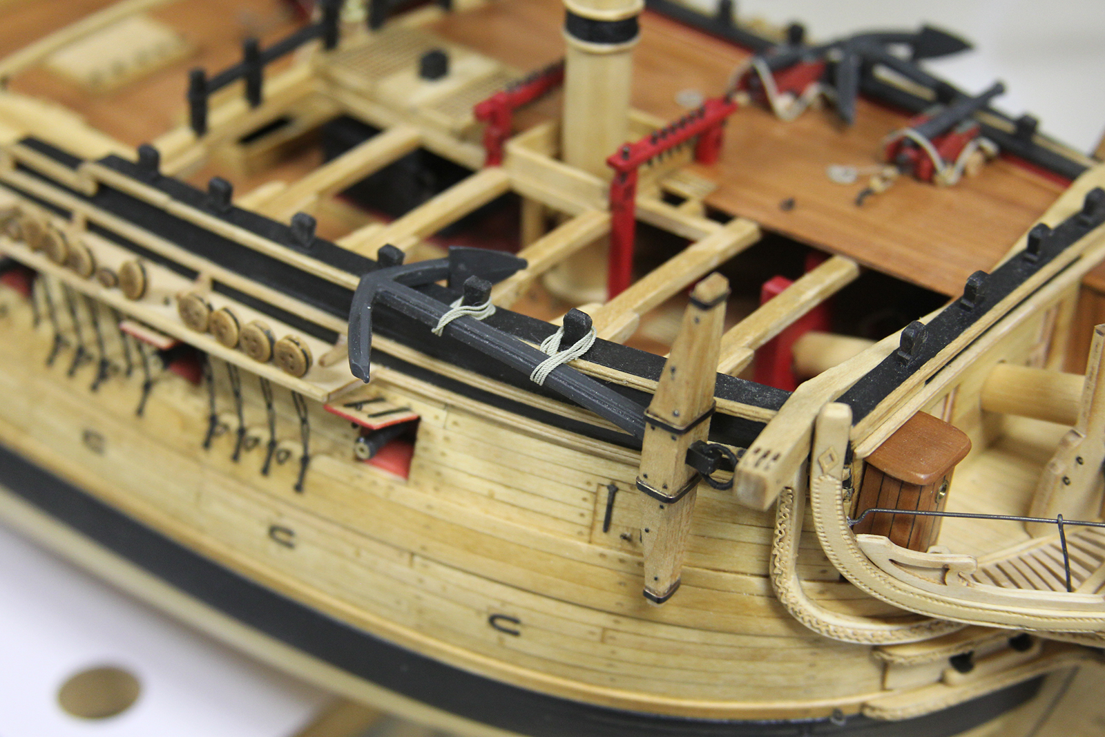
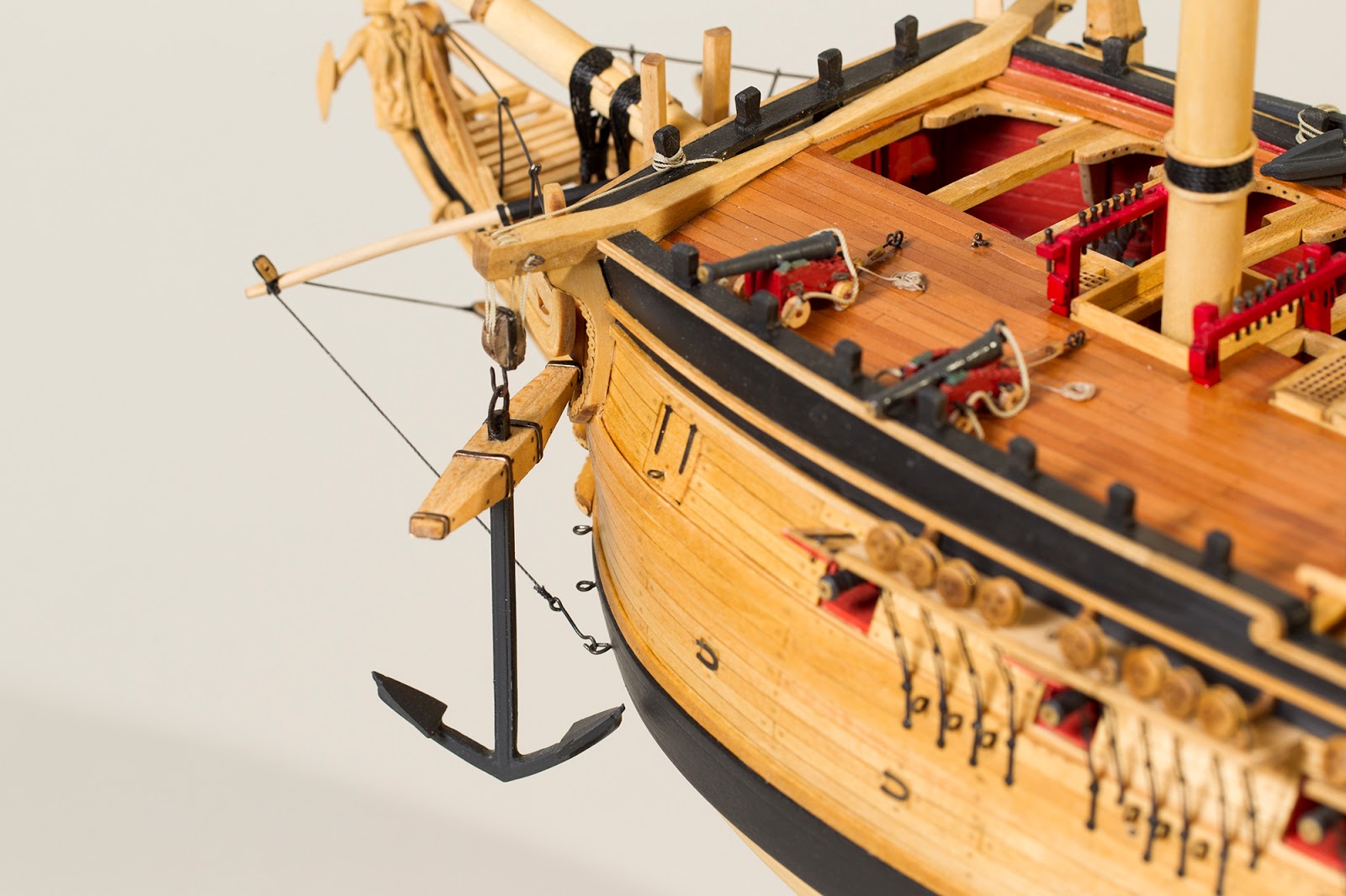
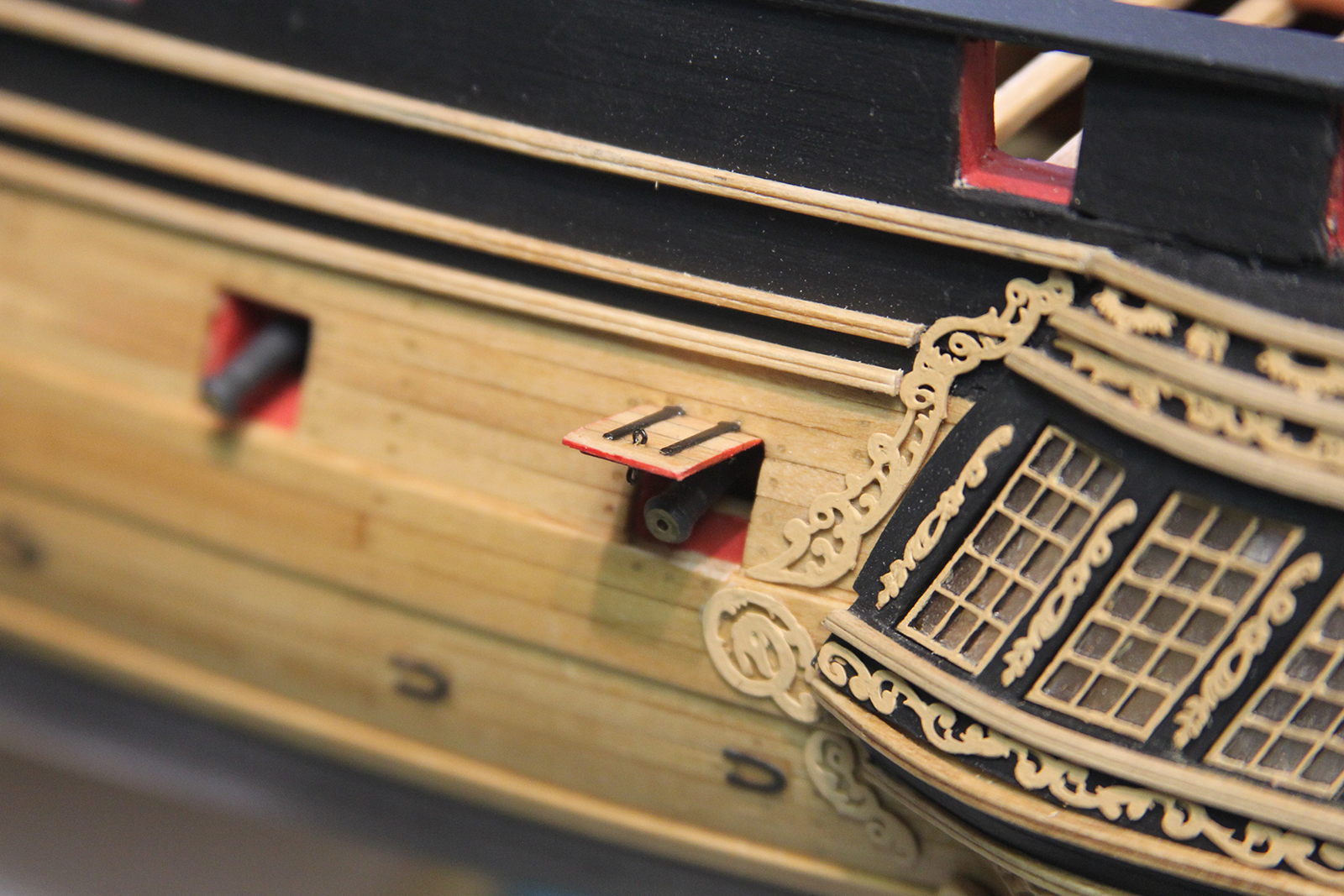
Typically on an Admiralty model, the anchors are merely secured to the side rather than actually rigged to the cathead. This is the procedure I followed for the starboard side of the vessel. However, when I went to secure the port side, I noticed a problem… because I’d added extra guns, merely securing the anchor would interfere pretty significantly. So, even though this will essentially be the “back side” of the ship to the viewer once mounted, I decided to rig the anchor to the cathead.
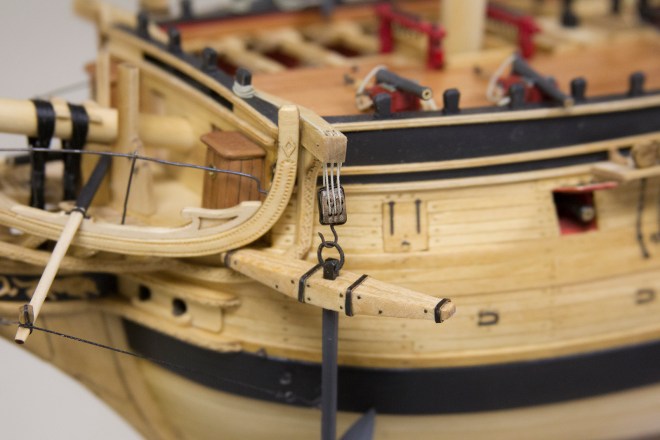
Not only does this provide for an interesting level of accuracy, but also gives her a little variety. Rigging the anchor to the cathead means manufacturing a rather large pulley with a hook attached, then drilling out the sheeves of the cathead itself. Overall, I’m pleased with the look.

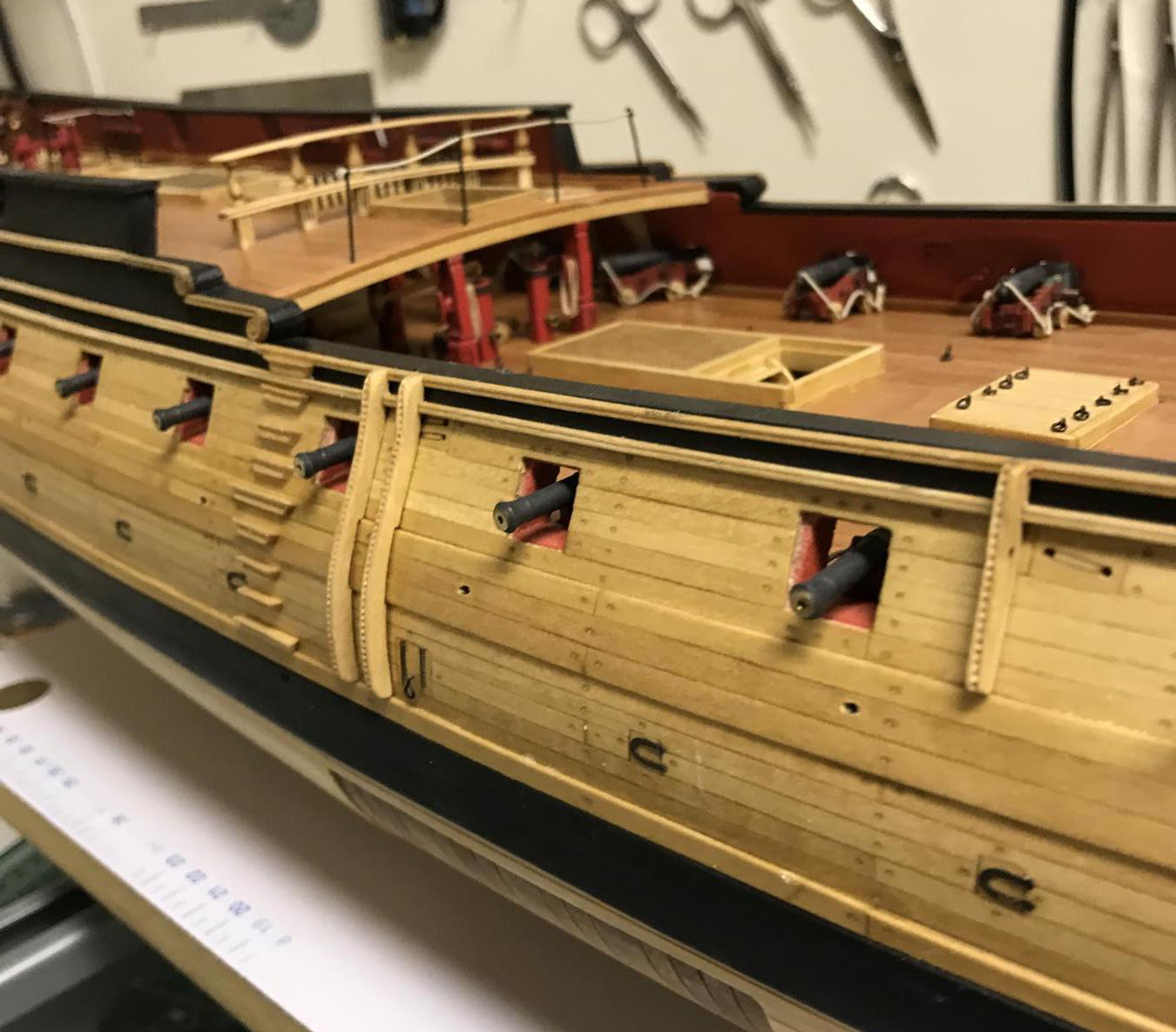
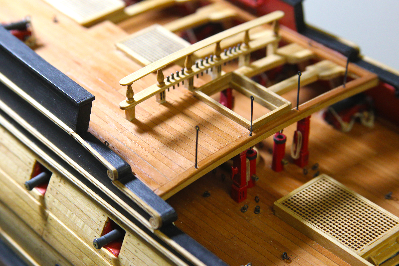
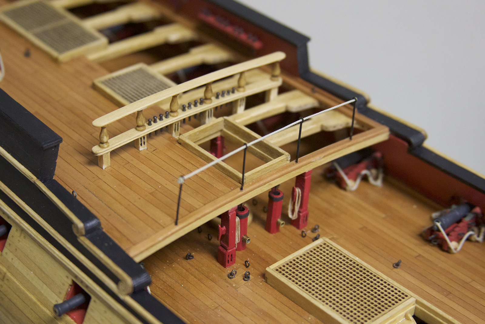
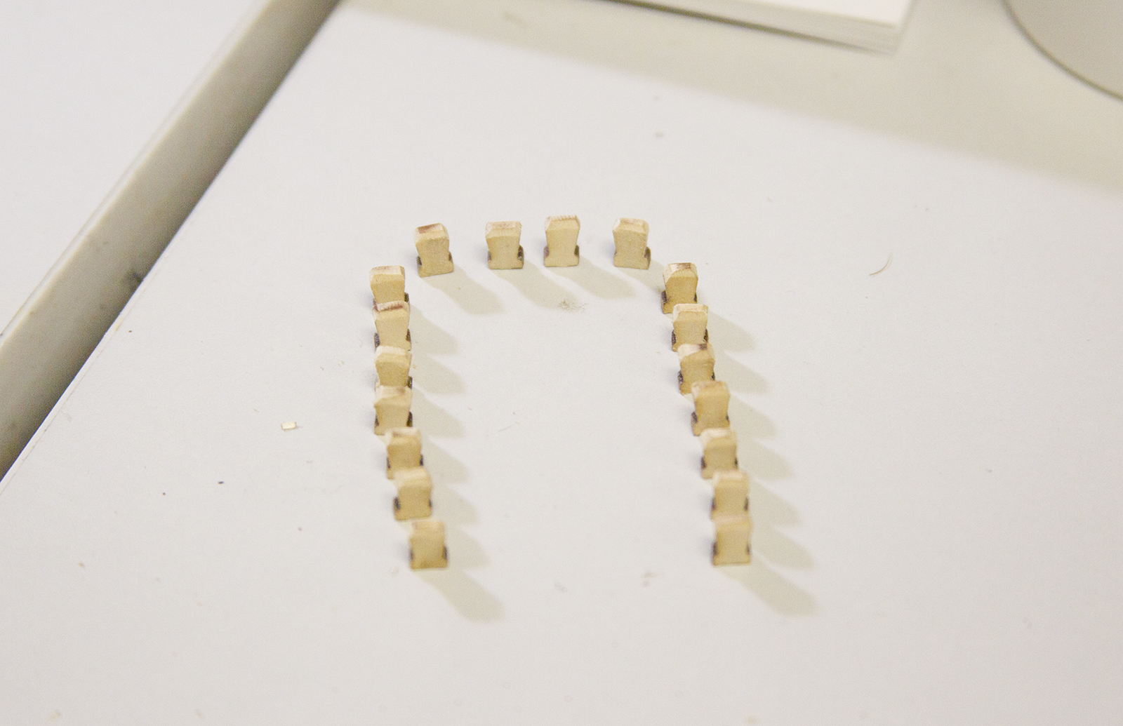
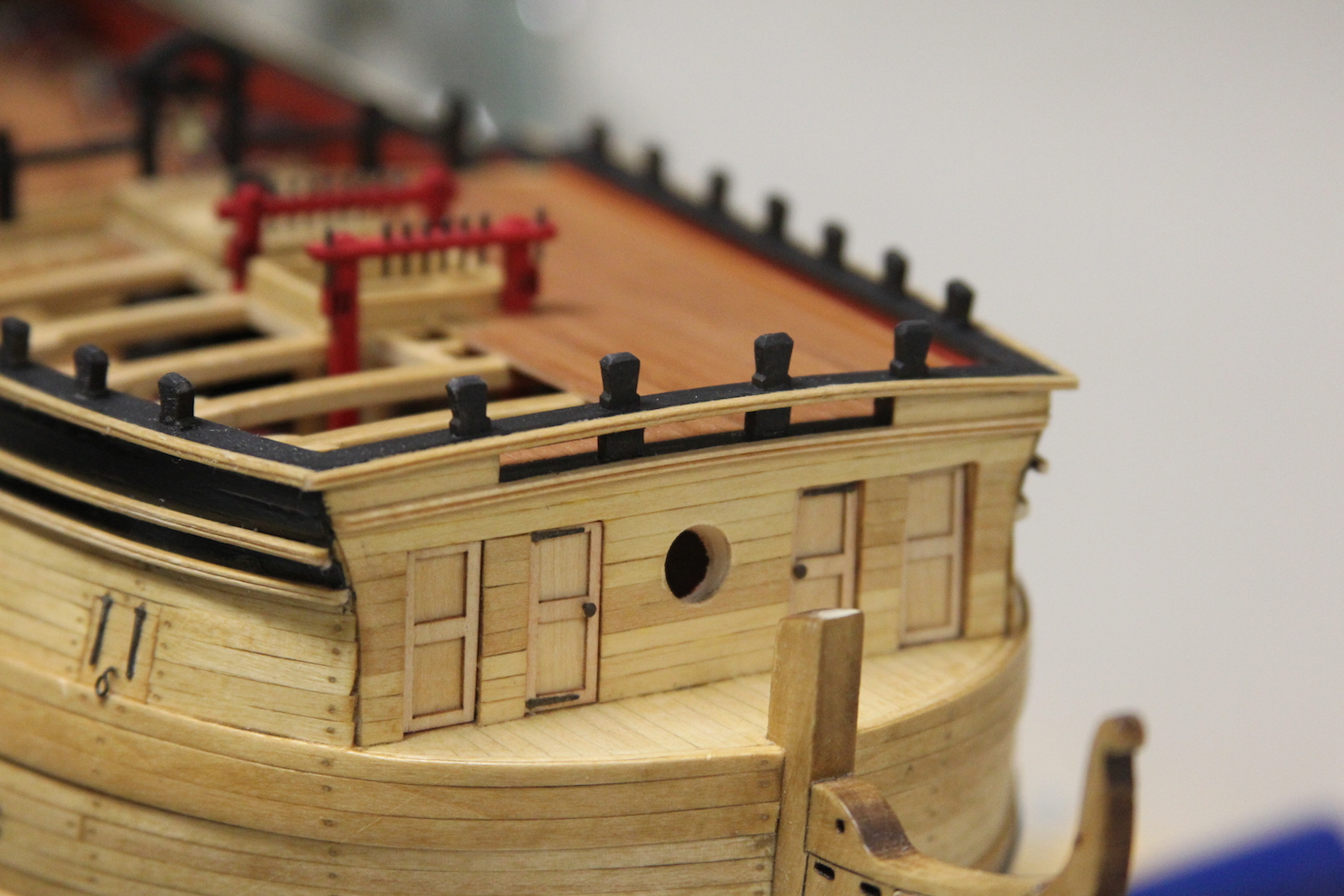
Another small, but important detail – the waist stanchions and railings. It’s pretty straightforward work, but requires a fair amount of precision. Each stanchion is placed in a predrilled hole, but the height of each stanchion is measured independently to ensure that the overall railing remains parallel to the deck.
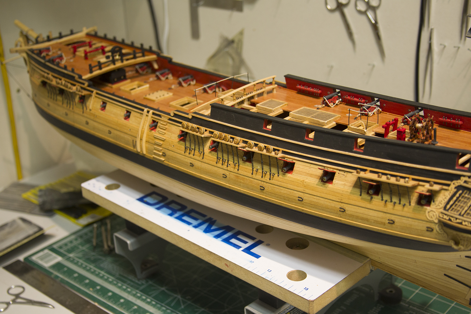
Finally – I took a small but significant step. To this point, the ship was being worked on by being mounted to a clamped work desk. I’ve made the transition to what will be her permanent stand.
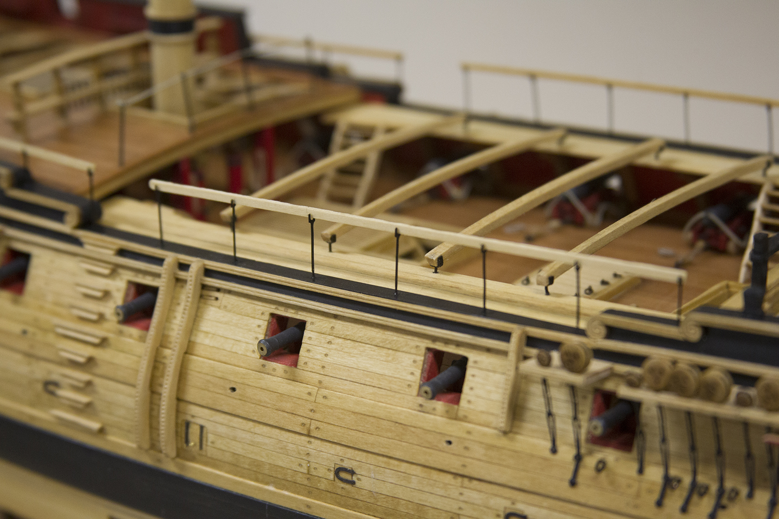

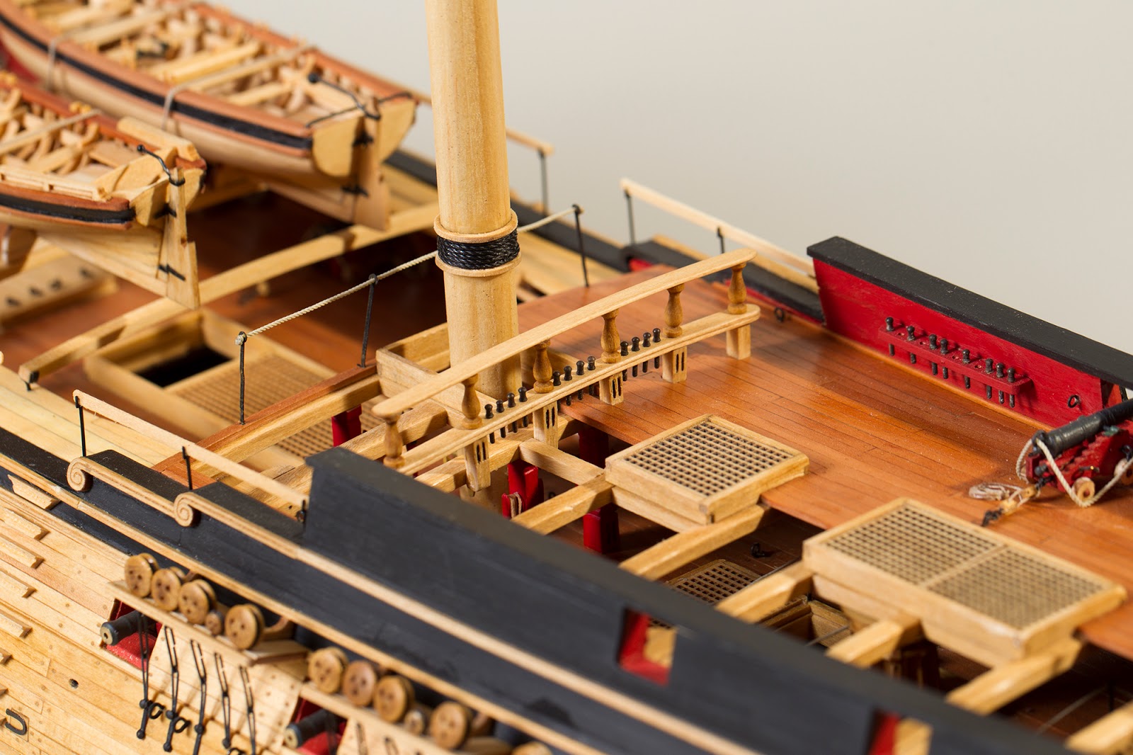
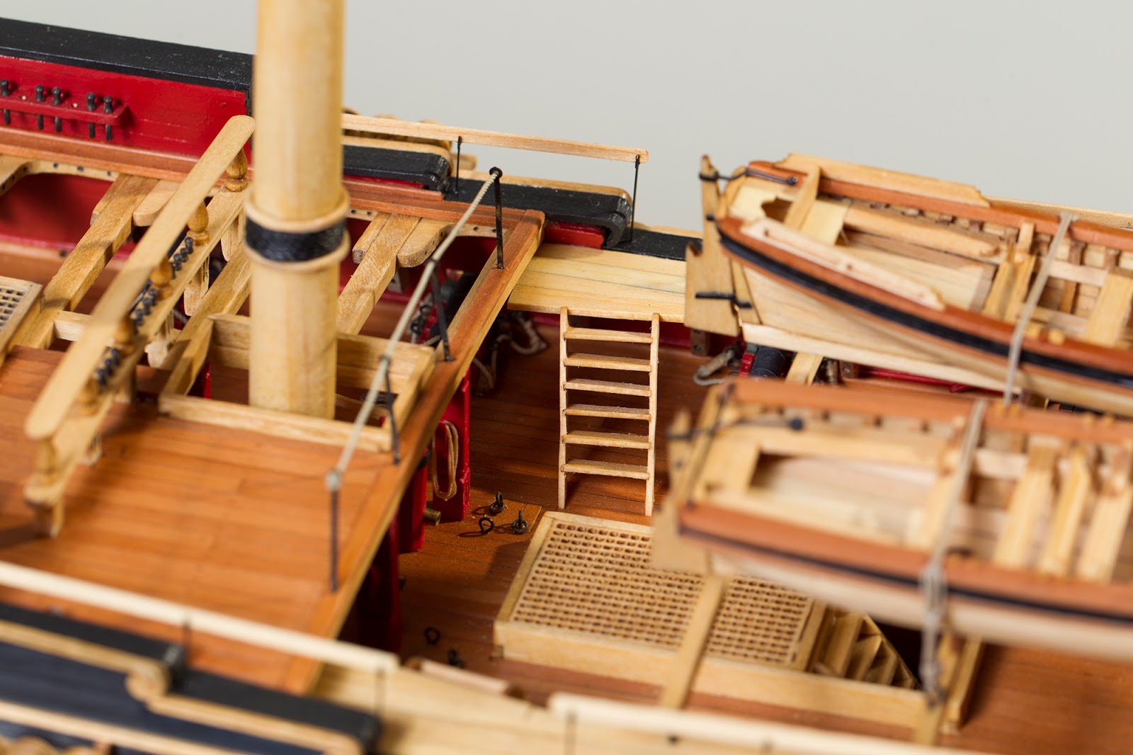
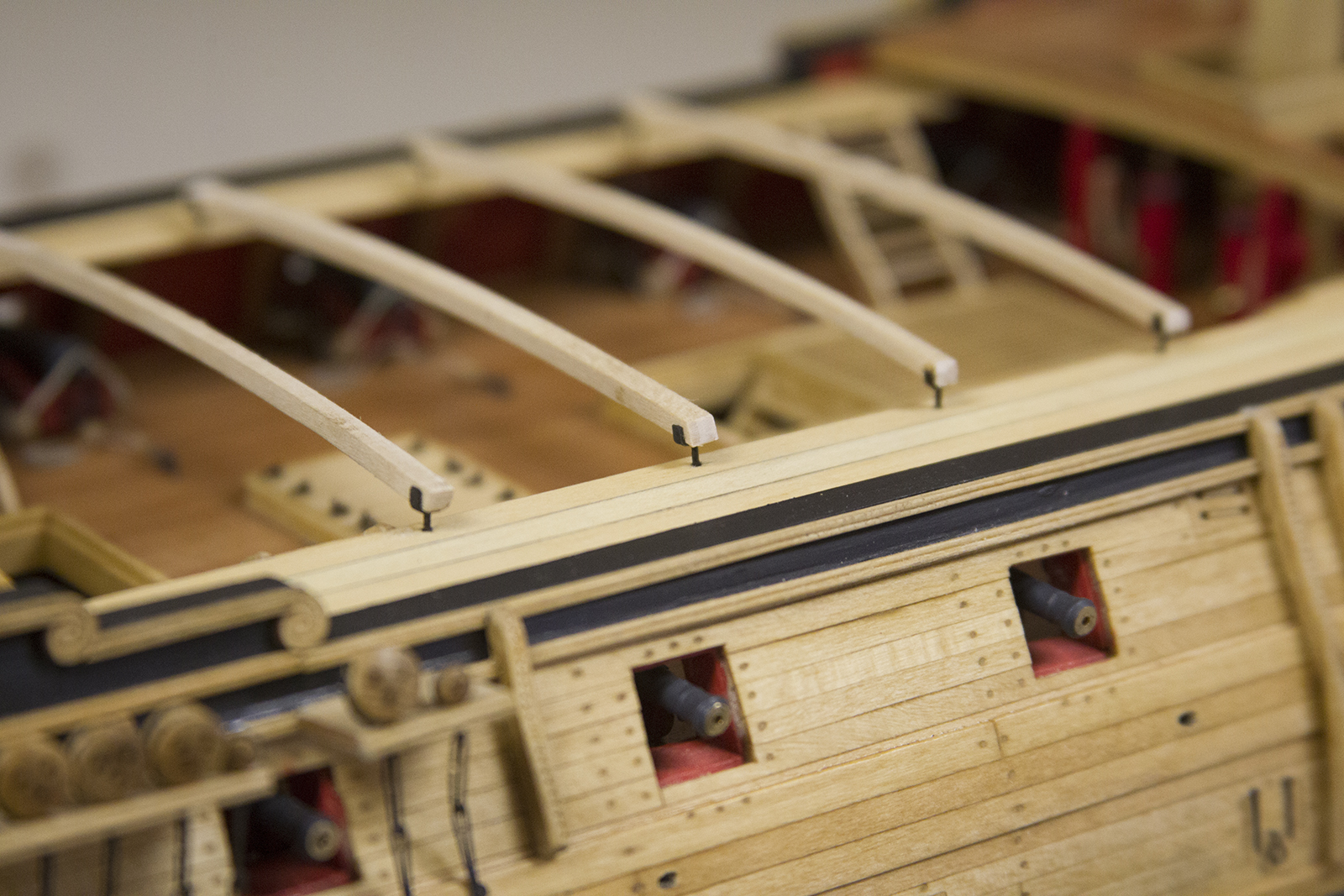
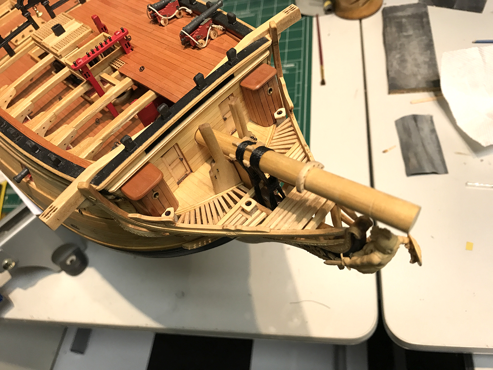
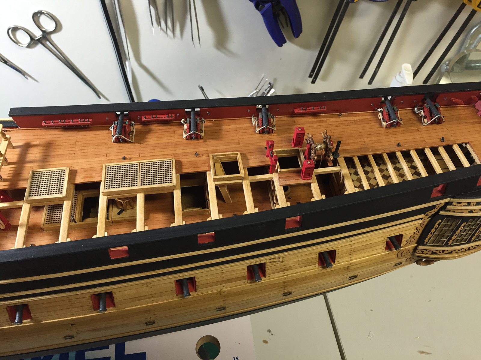
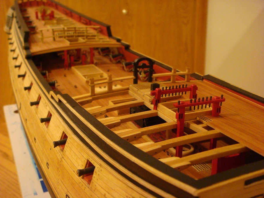
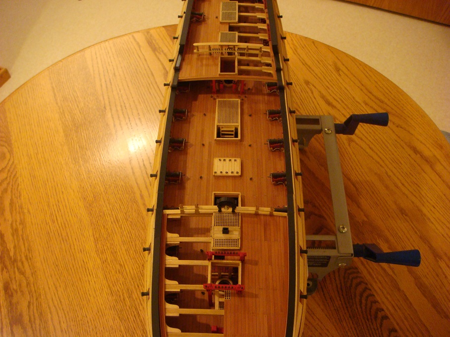
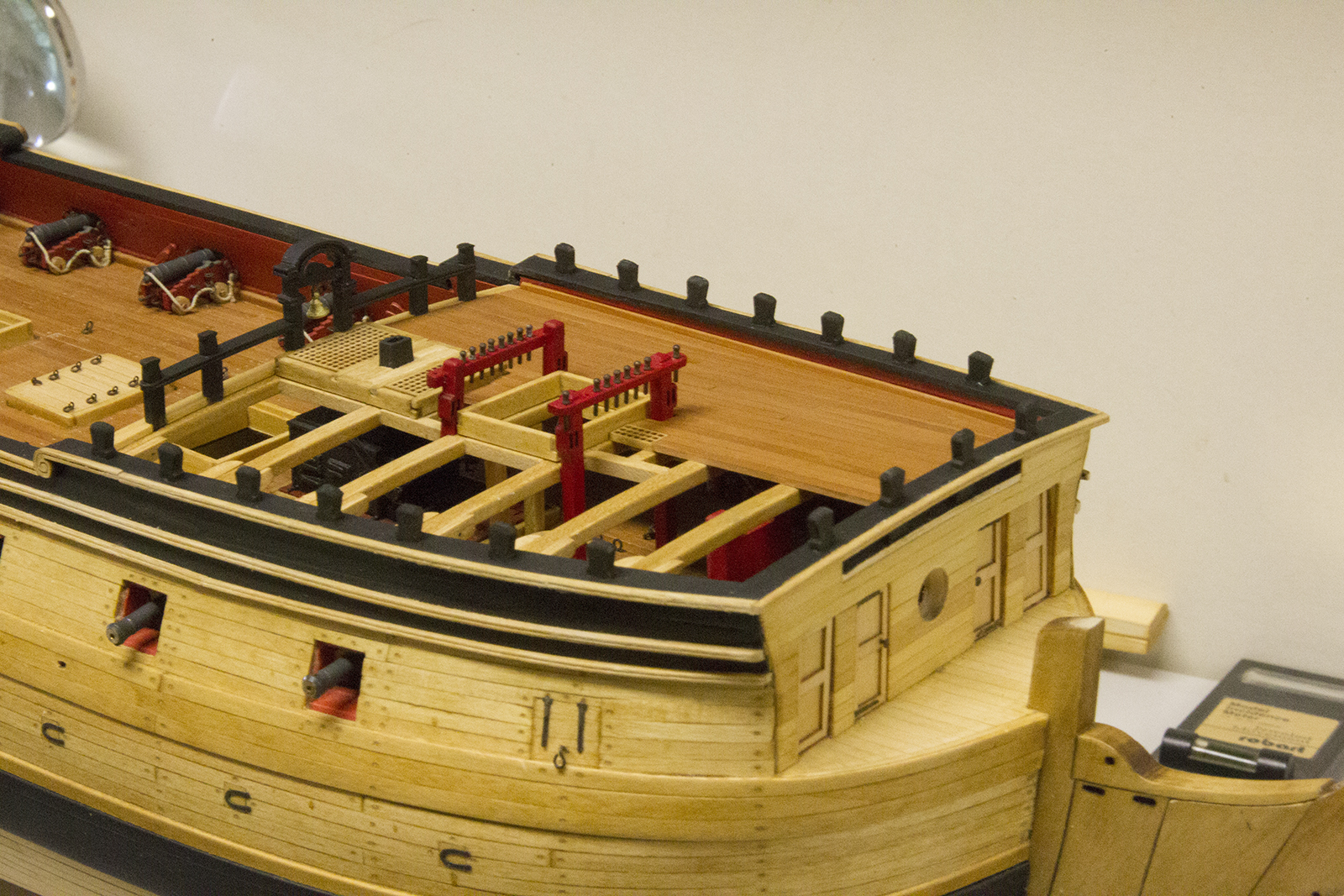
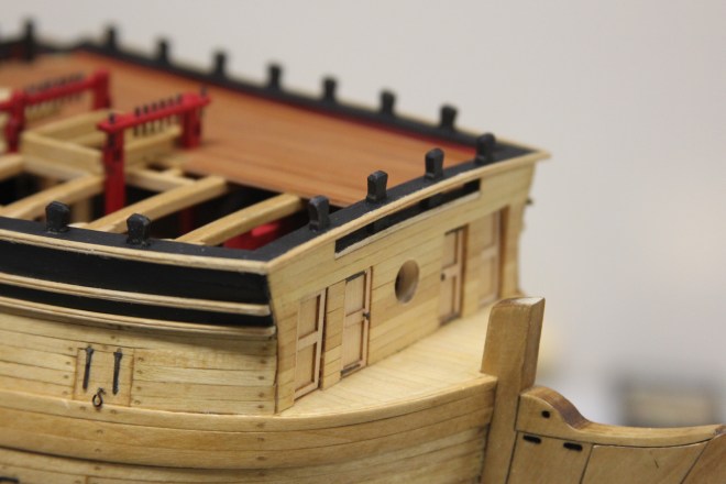
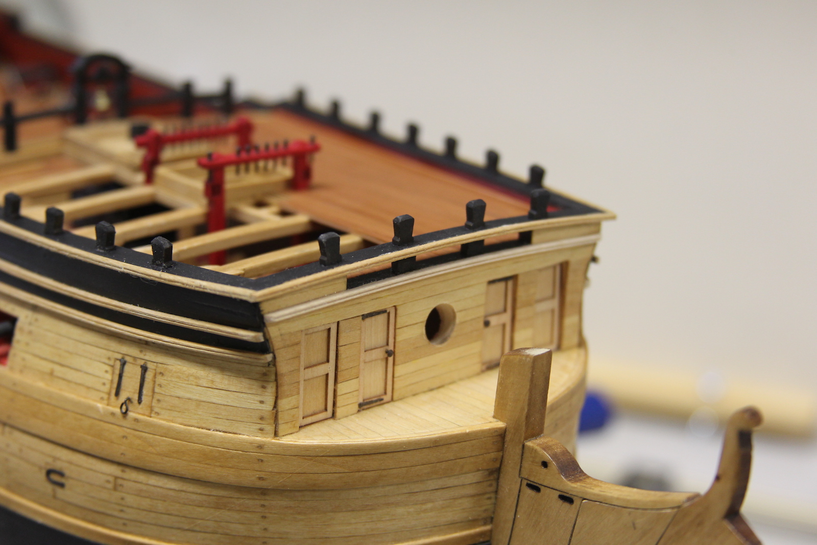
The waist of the ship is the open area that is most exposed to the weather. This section of the deck is ‘closed up’ with gangways on each side, then skid beams that run the width of the ship. Eventually, the two small boats will be secured to the skid beams.
I really struggled with the decision of either closing in the waist with the Swiss Pear that the deck was planked with, or closing in the waist with the lighter wood. Ultimately, I decided on the lighter as a means – artistically – of bringing the two very distinct colors together. Knowing that the cross beams and the small boats would be lighter, I wanted to tie it all together. I figured that if everything was the darker pear, and the beams and boats were light, it’d just be a bit too much of a contrast.
At any rate – I’m not overly confident in my decision, as there is a definite disparity in having the gangways a different color than the rest of the planking. A this point, I’m pretty sure I don’t want to tear it all up and re-do it to see how the Pear looks. I do intend to trim the smaller boats with some pear to bring it all together.
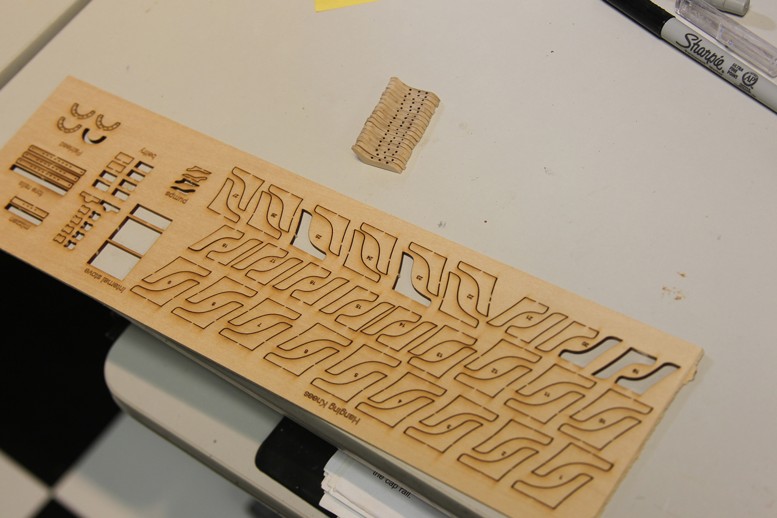
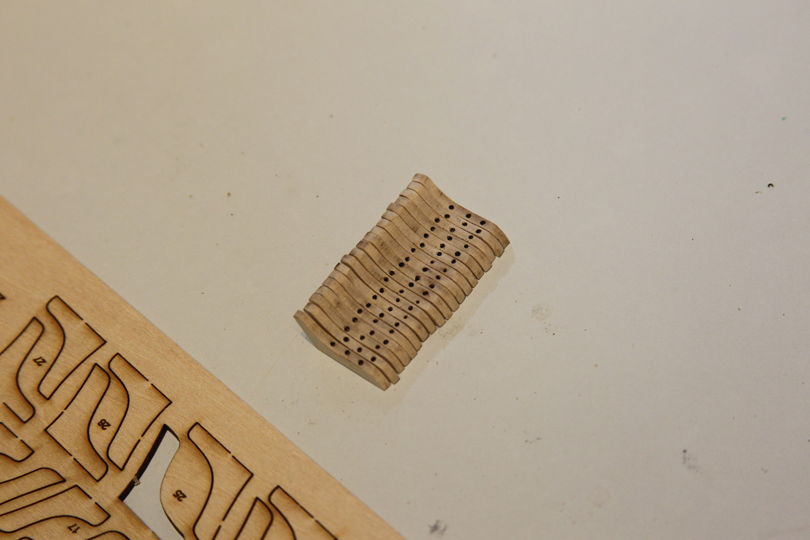
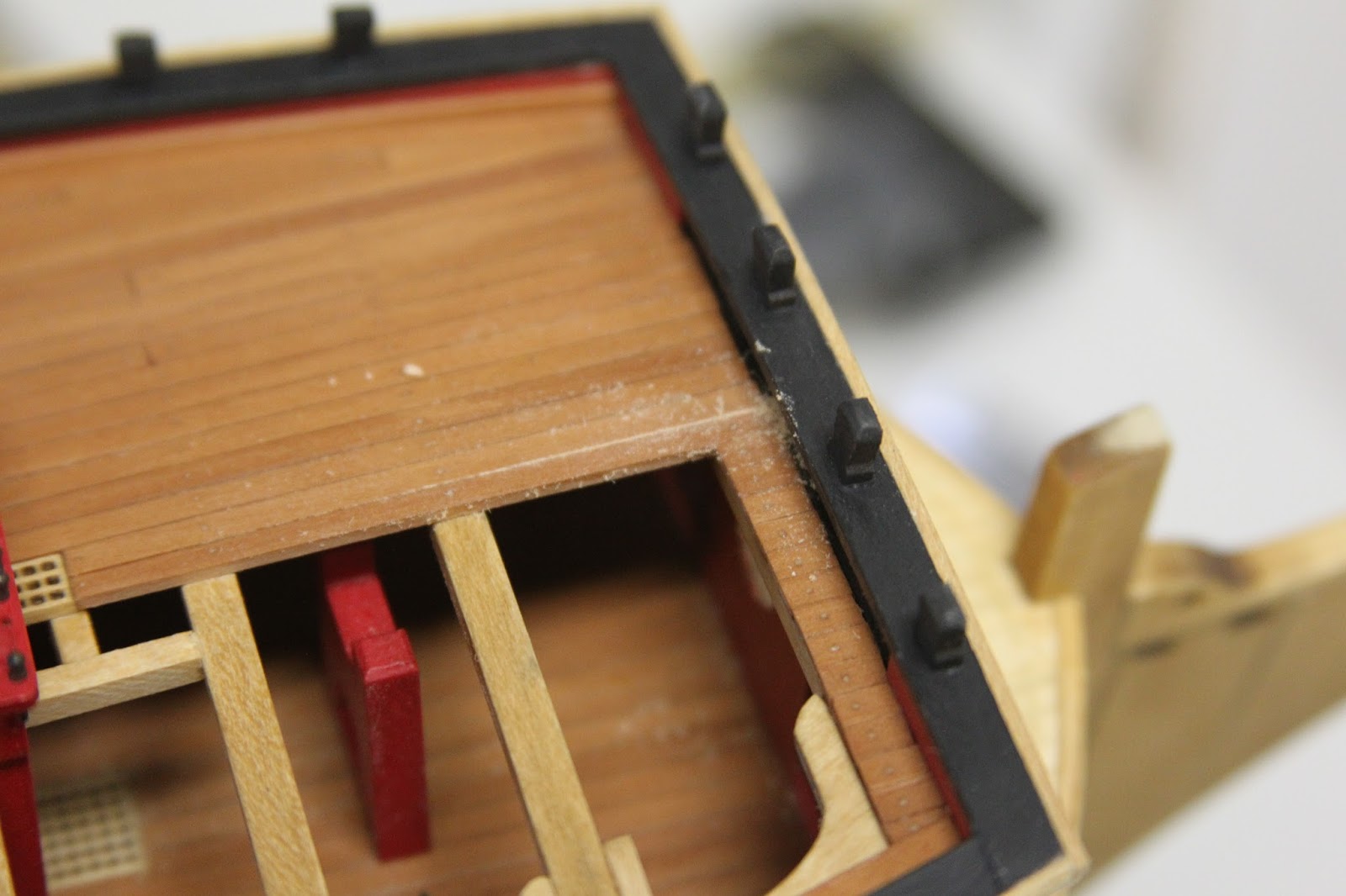
I started with the waist by sanding down and adding holes to all the knees. Pretty straightfoward stuff here. My own personal method of the “nails” was to drill out three small holes, then poke them with pencil lead. I took essentially what Augie did with the other deck knees to try and keep some consistency.
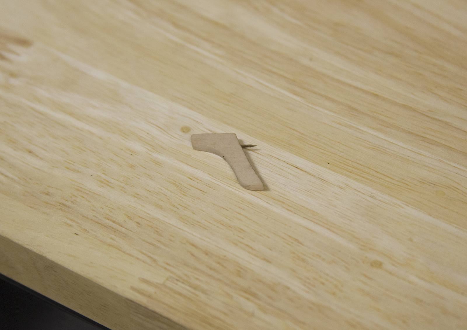
The knees didn’t hold to the bulwarks for crap no matter what glue I tried. Especially with the red paint having already been coated with a satin laquer of some kind. So I posted some brass nails into each knee to get it to hold solidly in place.

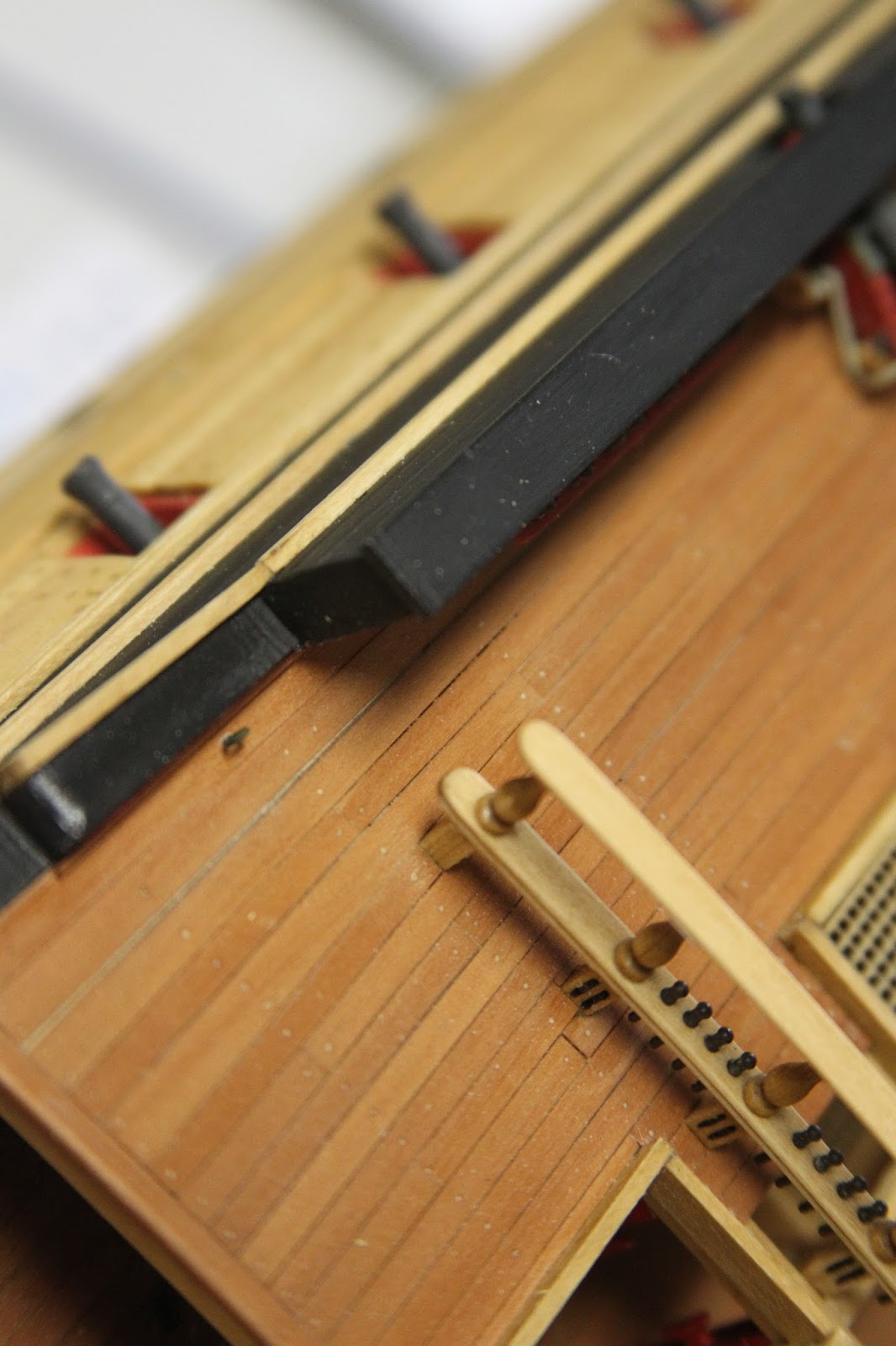
On to the gangways – the usual method of planking, glued some strips together after lining the edges with pencil lead to simulate the calking. Worth noting here that I had to do the Starboard side twice, because the first time I trimmed it too short. Ugh. What’s that old saying – measure twice cut once? (Yeah – and my father was a carpenter for 30 years, so let’s not tell him about this mistake, shall we?)
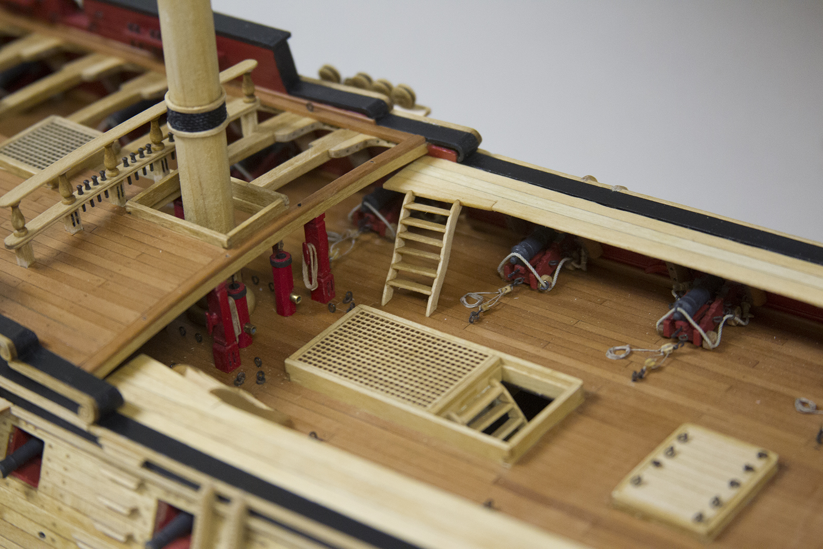

Oh …. ladders…. I pretty much hate ladders. I blow through quite a bit of wood here because I botch them pretty consistently and end up having to red-do a lot of steps, etc. Then, it’s still a struggle for me to get them anywhere close to even. Ladders are truly my achilles heel. The ladders (gangway stairs) are measured using a pre drawn plan for reference – then each side of the stair is sanded to create a groove with which to seat the steps. It’s then all glued together and each is mounted to the gangways.


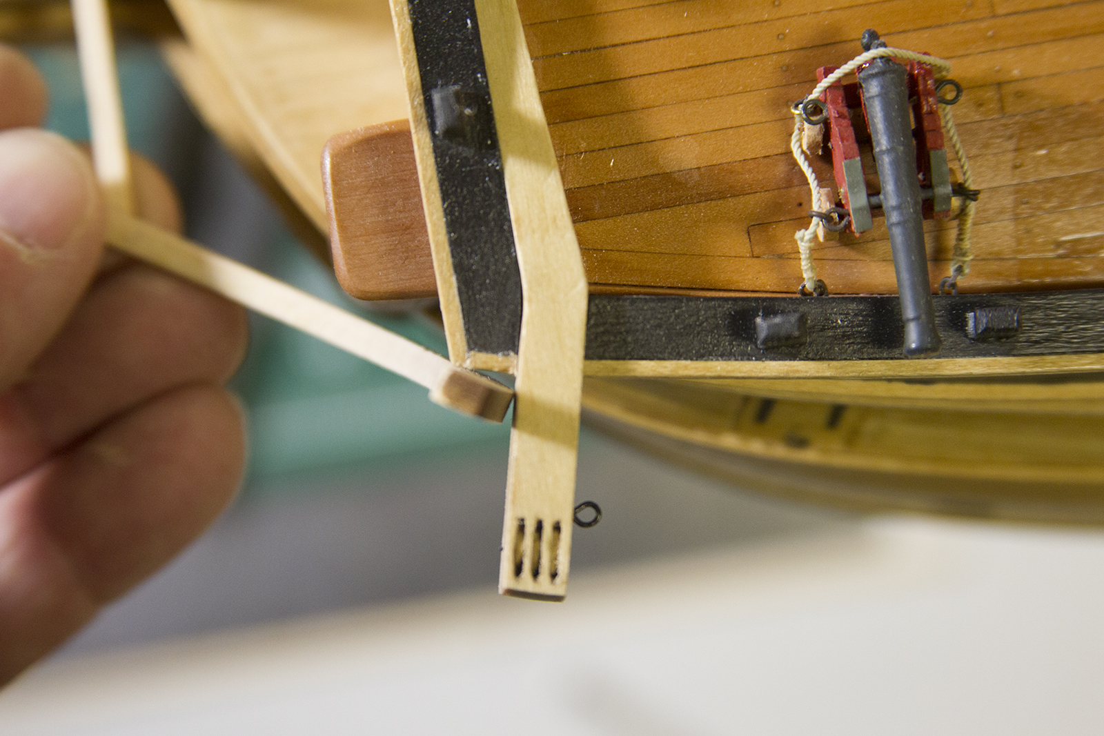
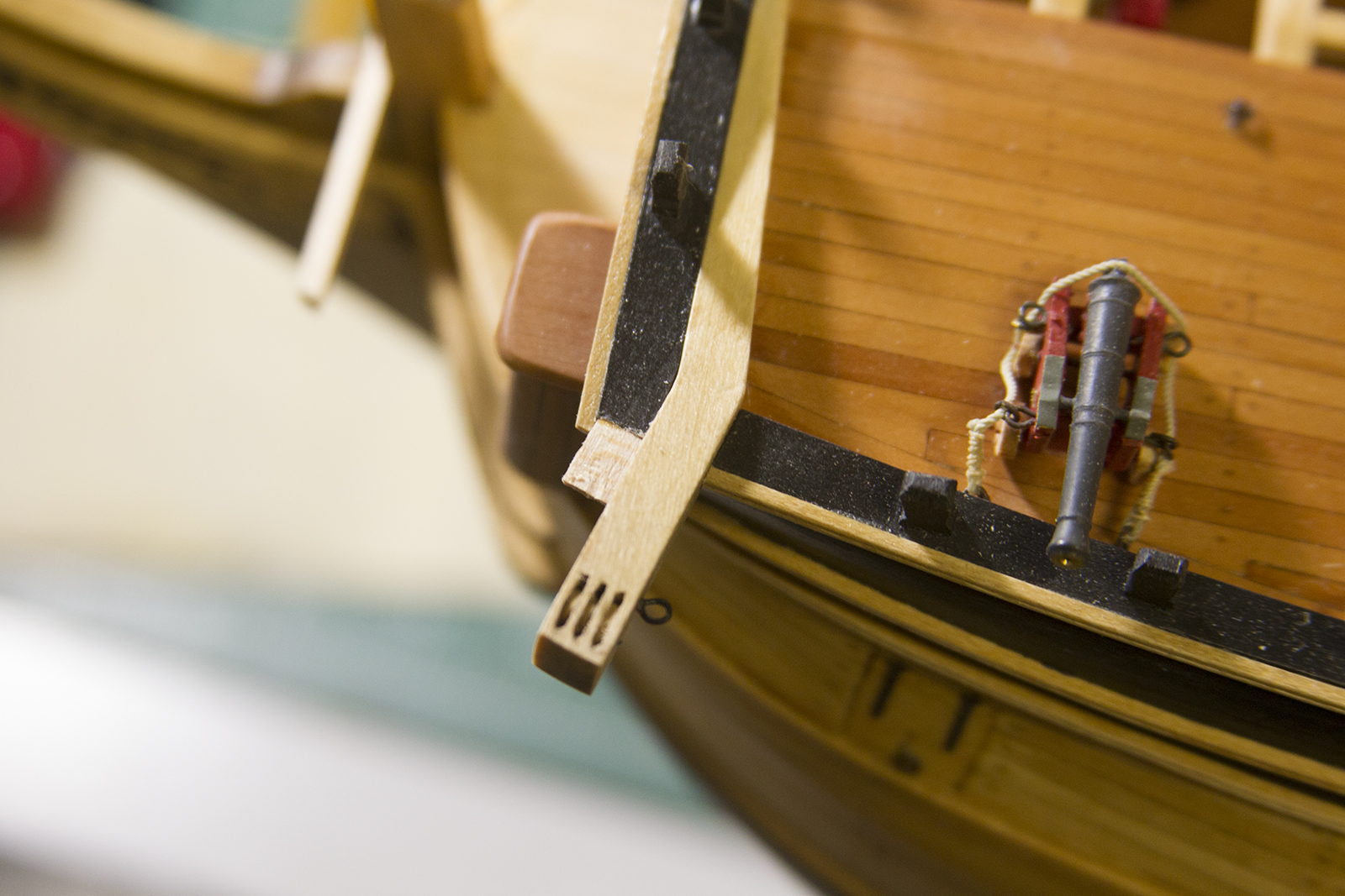
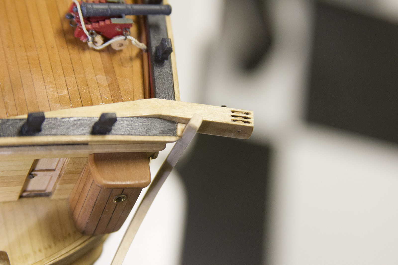
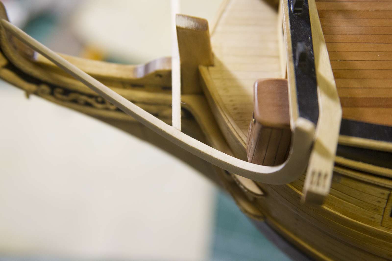
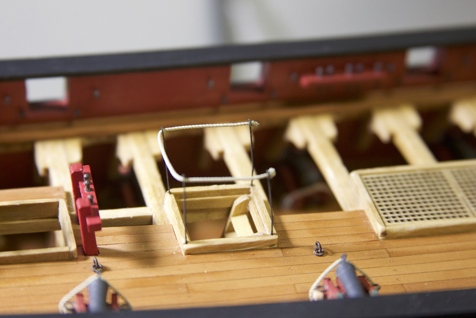
Each of the four skid beams is held in place using a small crutch. The instructions call for each crutch to be made from cardstock, however once again I used small strips of metal – as the patina’d metal is much more natural and authentic looking to me. So I cut up some brass, bended it to fit, then drilled holes in the bottom to fit a brass nail. I blackened all of it, then mounted all the skid beams.
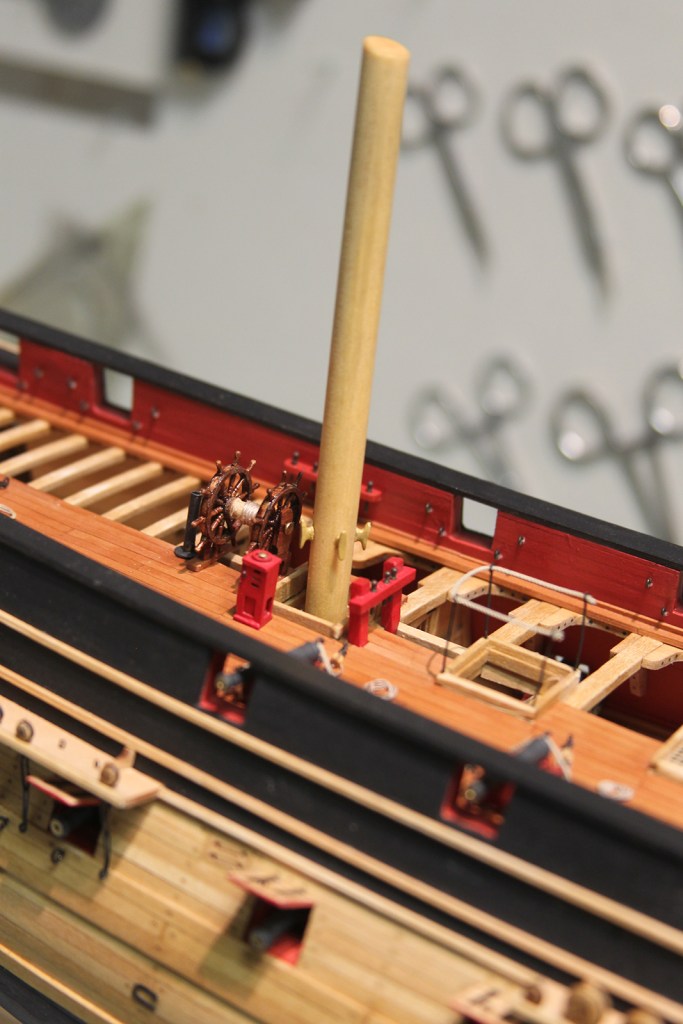
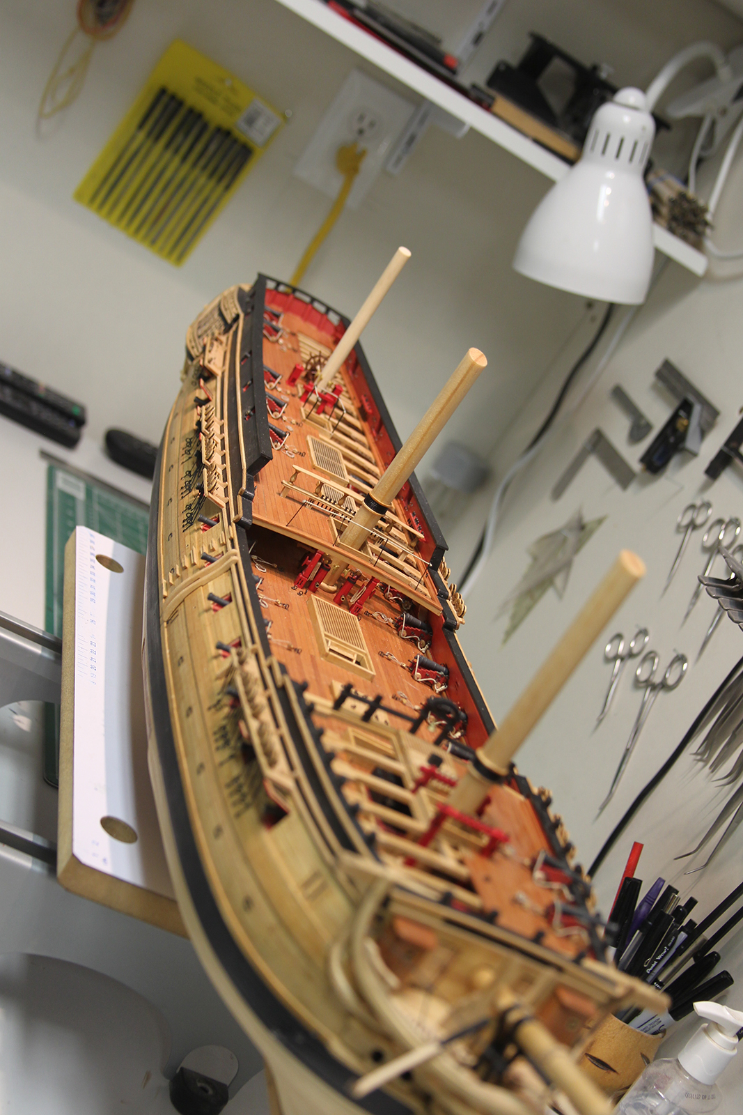
As I near the last stretch of the build, much of the work concentrates on small on board details. I’d been waiting for some time to erect the ships masts. Once again, as this is an “Admiralty” model, it’s not fully rigged, but rather supports partial masts.
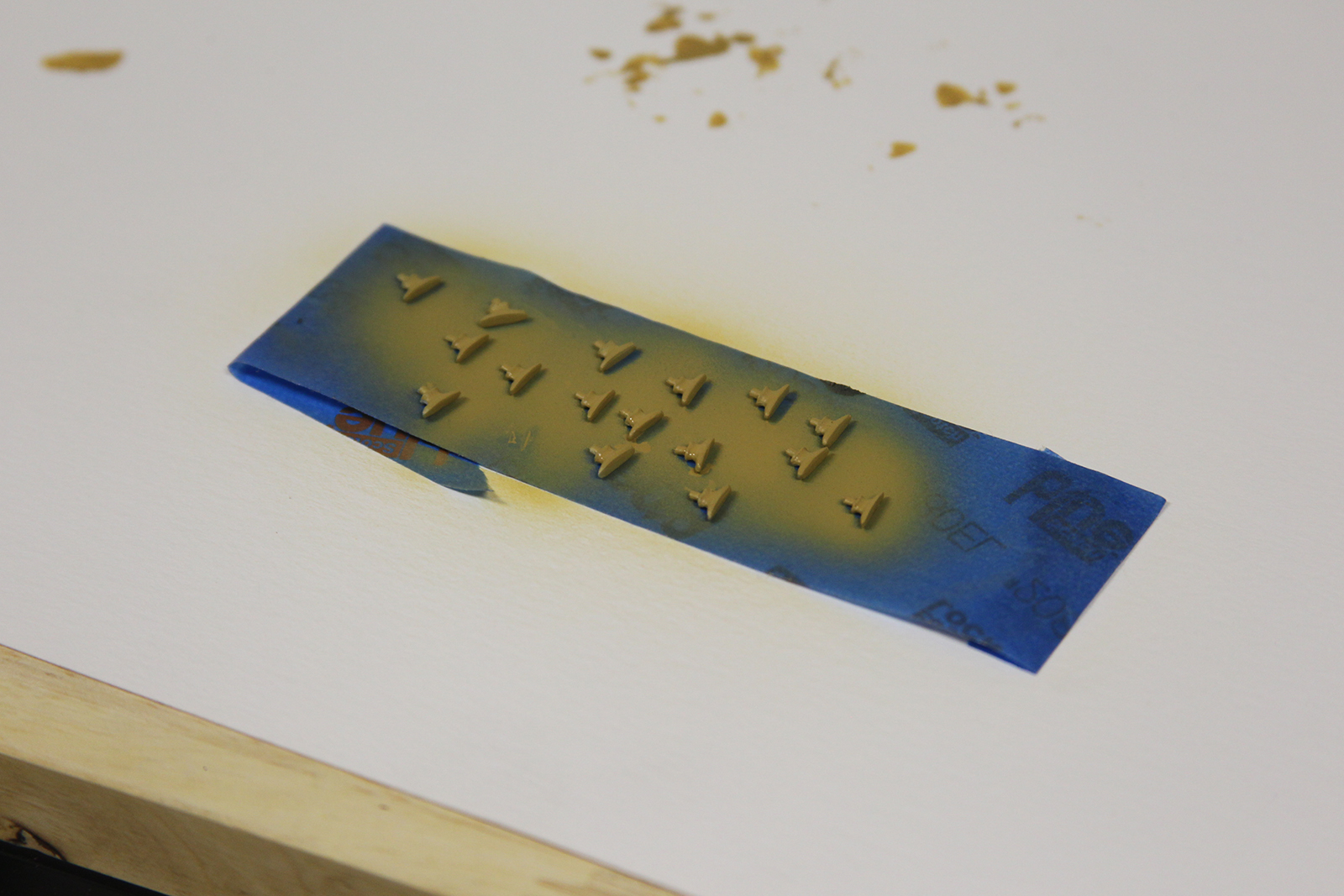
The fore and main masts are 13mm dowels, with the mizzen slightly smaller. Each mast is fitted with a set of either four or six cleats. I had a handful of cleats left over from another project, so it gave me a chance to use my snazzy new airbrush. Worked pretty well, except they all needed to be taped down – after my first attempt at ‘airbrushing’ blew them all off the counter and had me on my hands and knees picking cleats up off the floor. The color was a combination of Vallejo Airbrush colors light brown and yellow ochre.
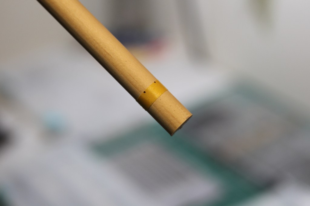
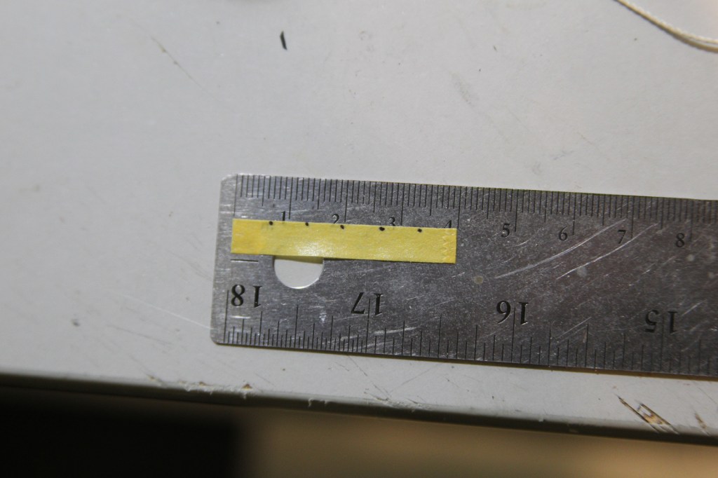
In order to get the cleats properly spaced, I used a thin strip of masking tape to measure the exact diameter of the dowel (after I did a little smoothing/sanding). I laid that strip onto my ruler, then equally divided it by the number of cleats needed. I then reapplied the tape to the mast, drilled the holes appropriately, and mounted the cleats.
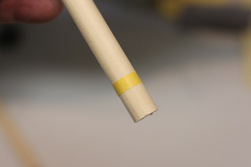
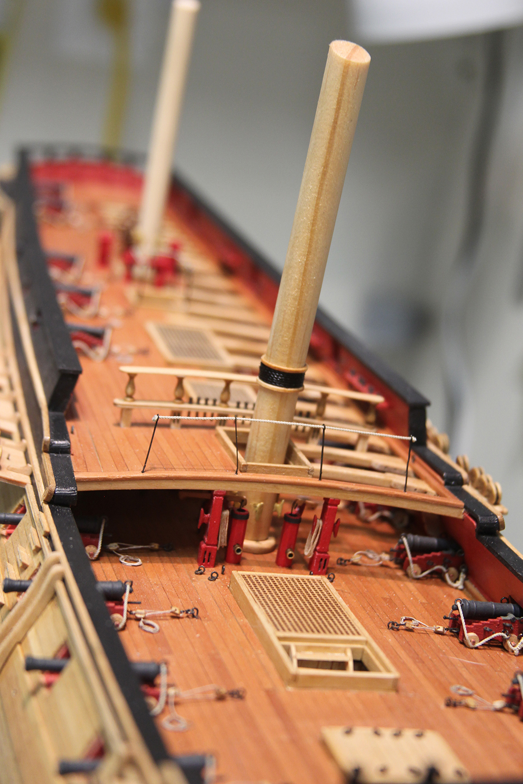
Each mast is also fitted with wooldings. Once again, the instructions call for heavy cardstock to simulate the wooldings, I decided to manufacture some using the extra laster cut mast bases.
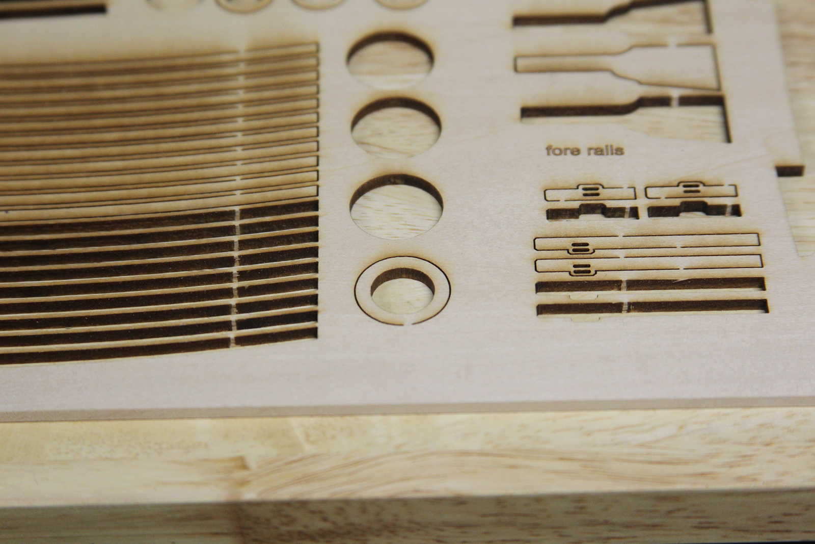
Each mast base was split into two pieces down the middle – which required some very, very delicate cutting. They weren’t perfectly even, but close enough to sand down to get even with the wrapped heavy rigging.
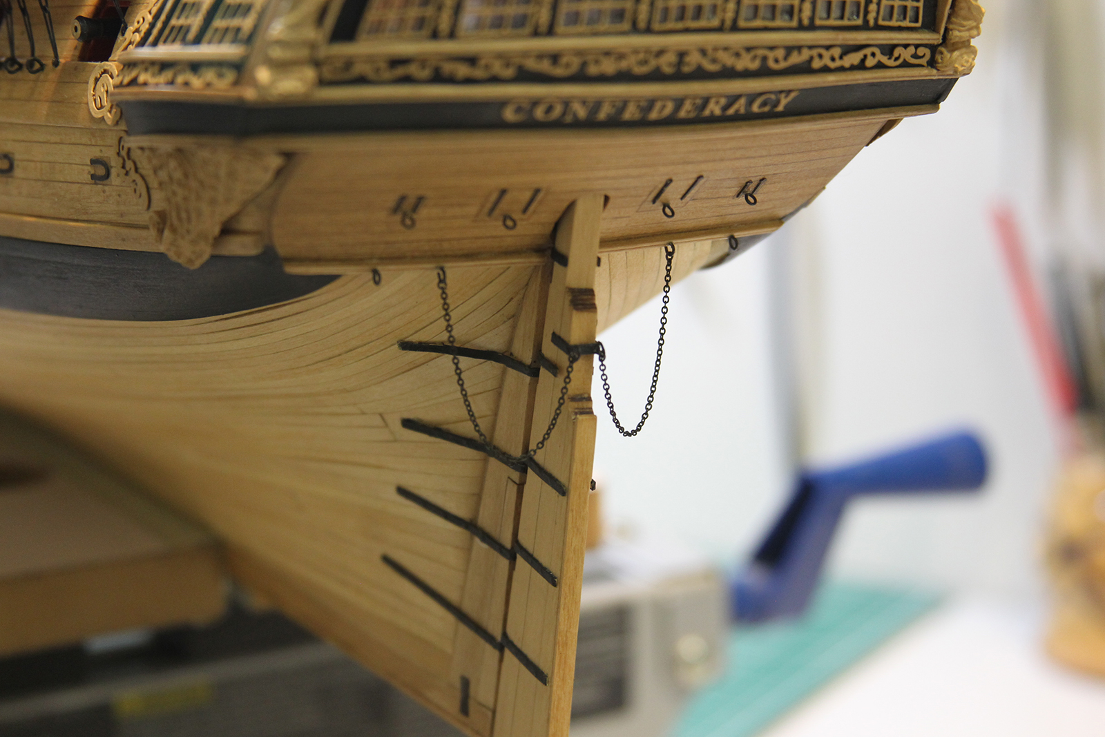
I also took this as a random opportunity to remount the rudder and rudder chains.
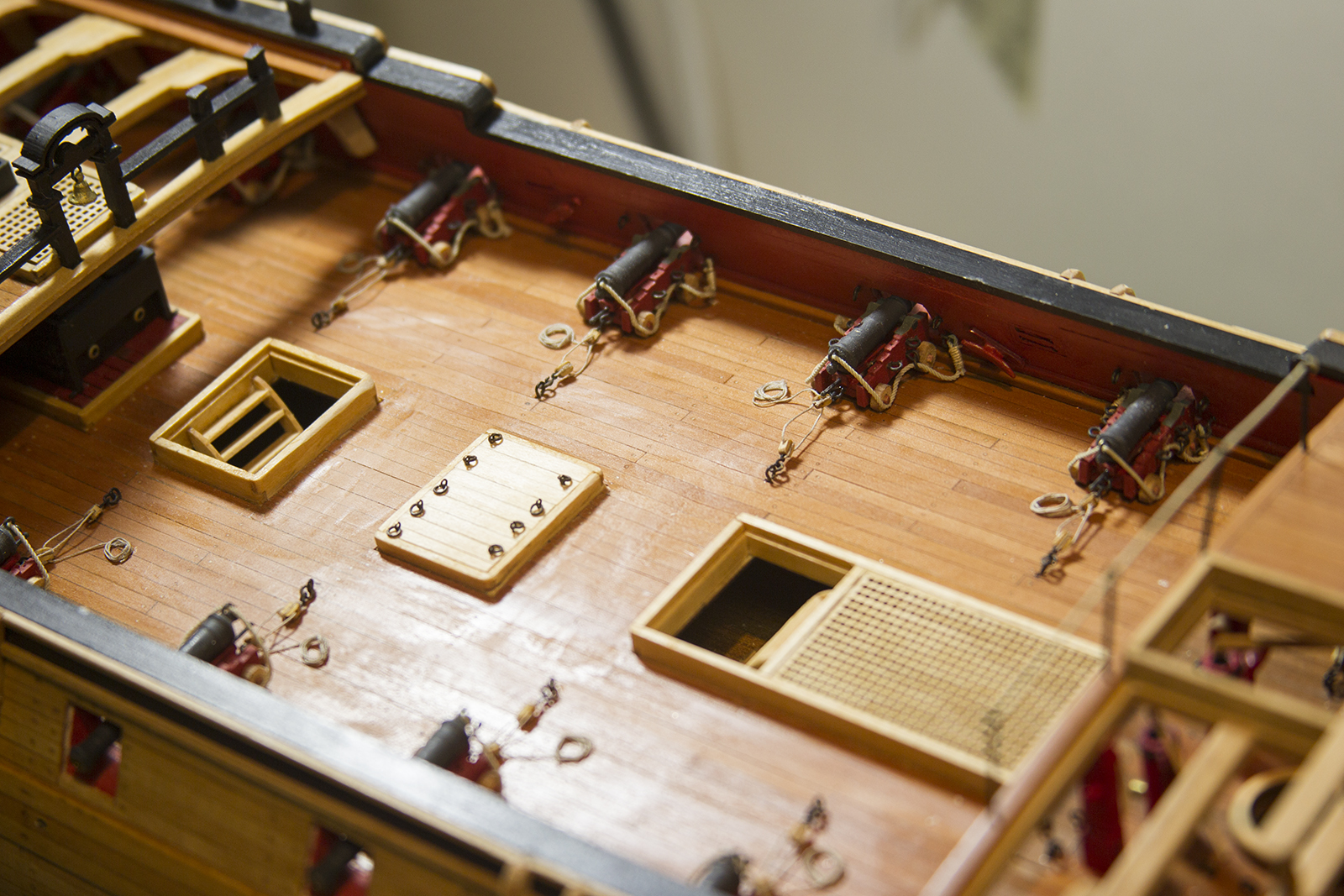
The chainplates are flat pieces of wood that run along the sides of the ship and hold the deadeyes in place. The deadeyes are the home for the ratlines and shrouds that extend down from the masts, crosstrees and yards, etc.
On this ship, there won’t be anything rigged to the deadeyes, but it remains important ensure that they are all even and arranged properly for accuracy.
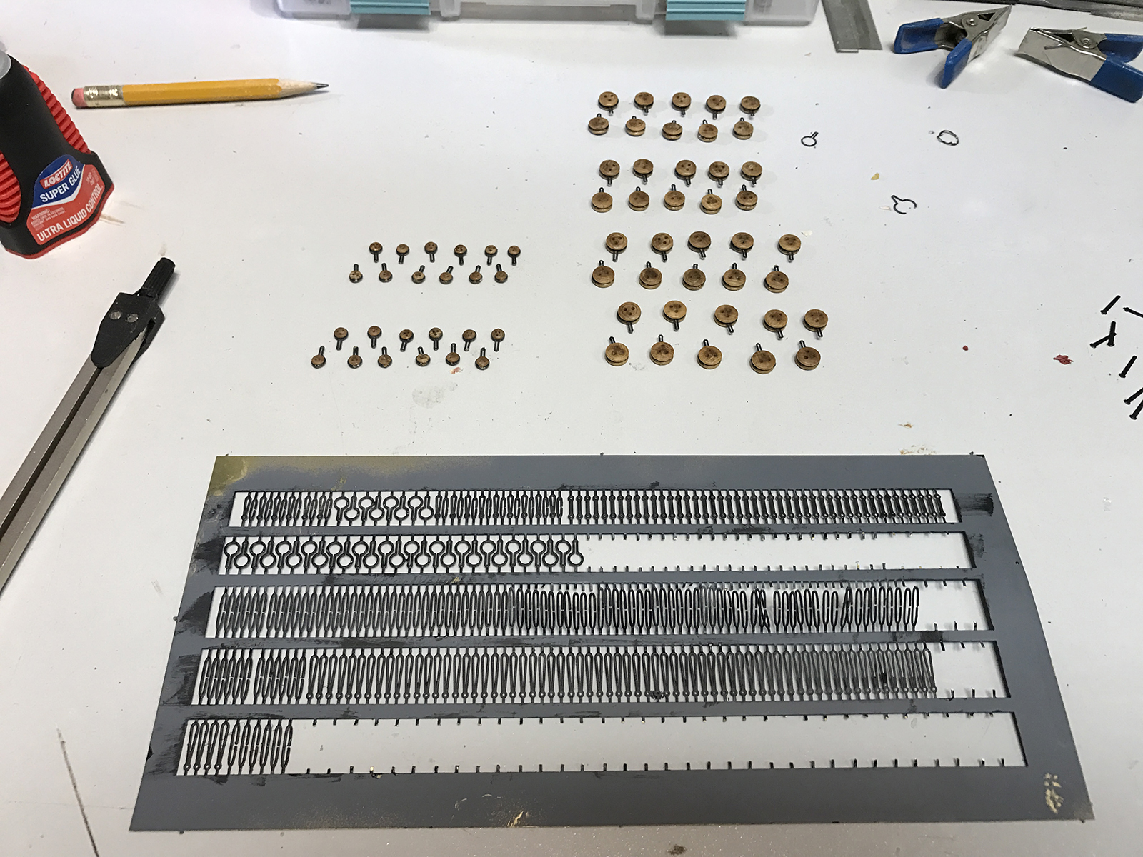
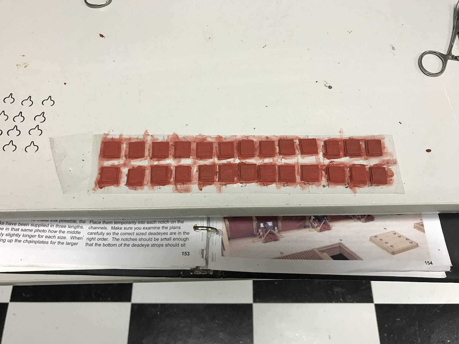
I began by prepping all of the deadeyes and parts (called strops) that will attached everything to the hull of the ship through the chainplates. While my first choice is to blacken all of the photo-etched parts to patina them, it was much more economical and efficient to just spray paint them.
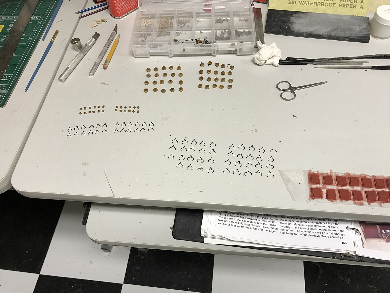
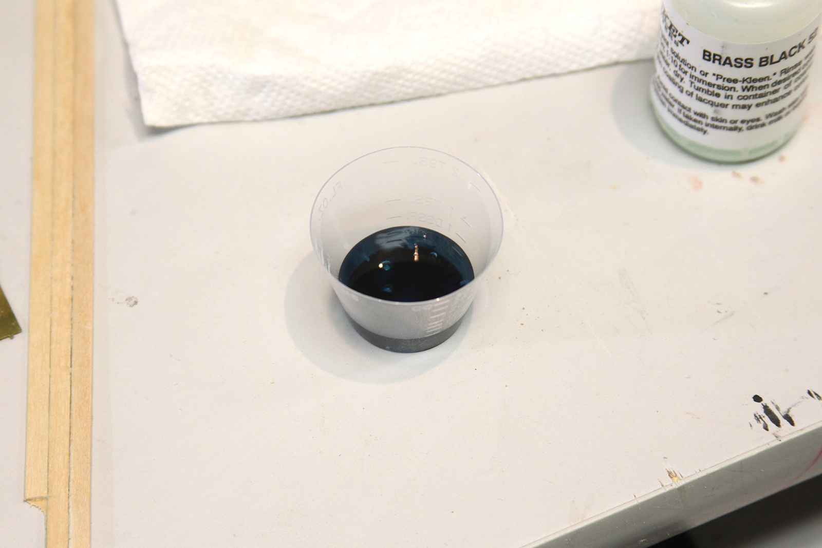
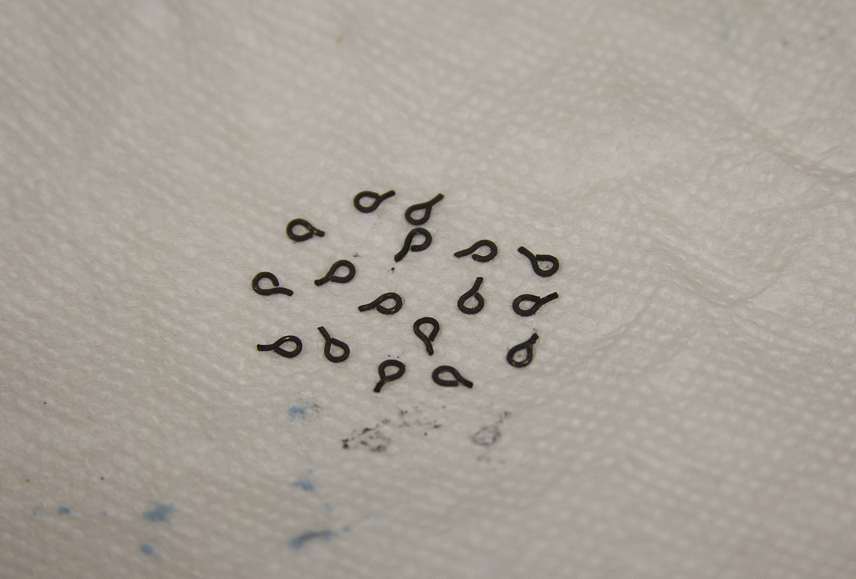
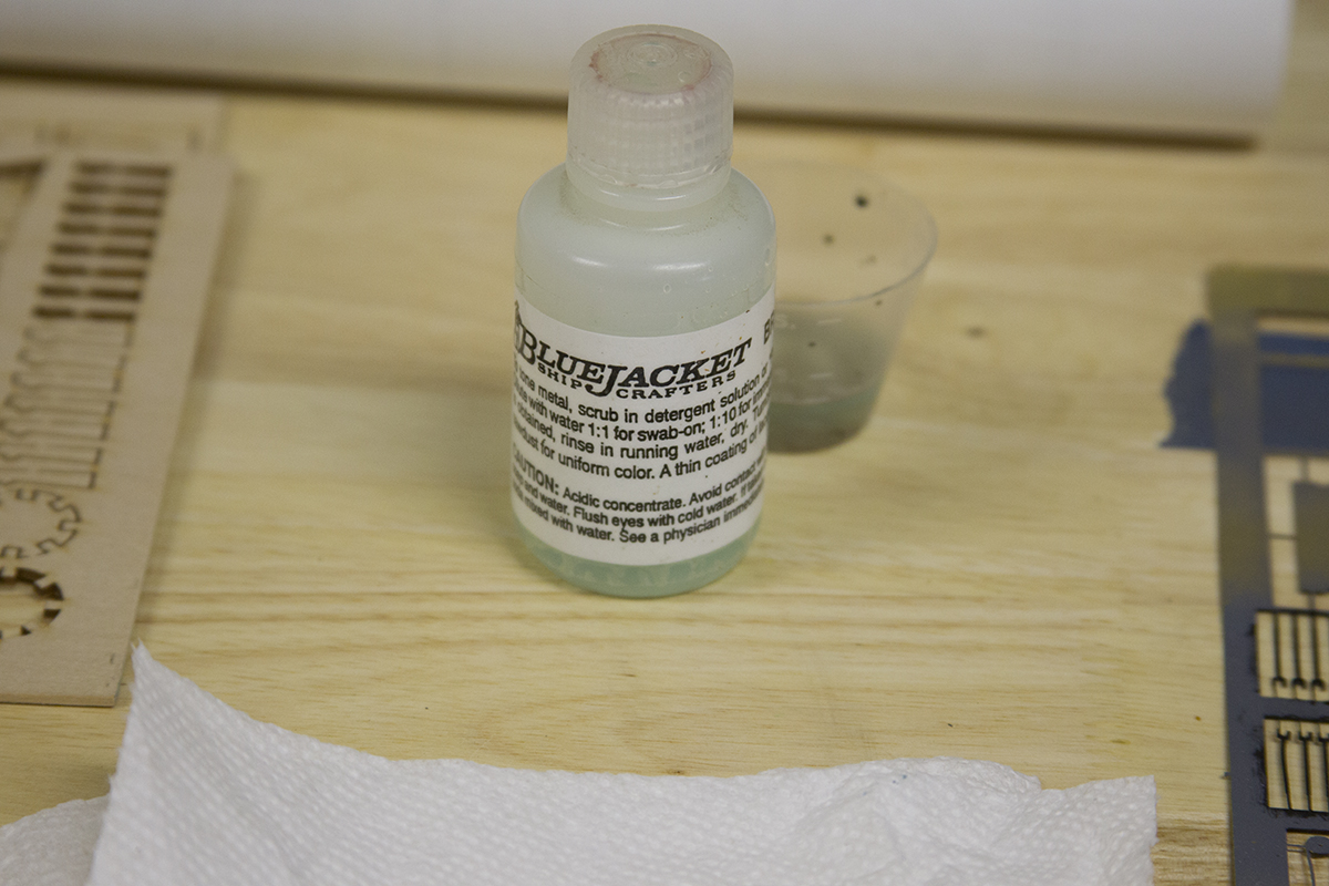
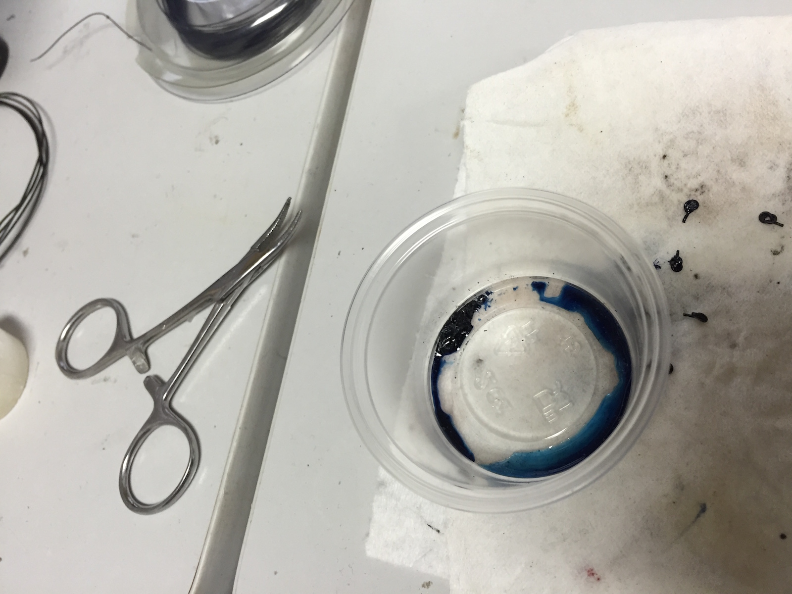
I did however choose to blacken the eyebolts and the nails using a 50/50 mixture of Bluejacket’s solution and water. The nails ended up darkening very nicely, but the eyebolts are sketchy at best. They’ll all require some touchups once everything is mounted.
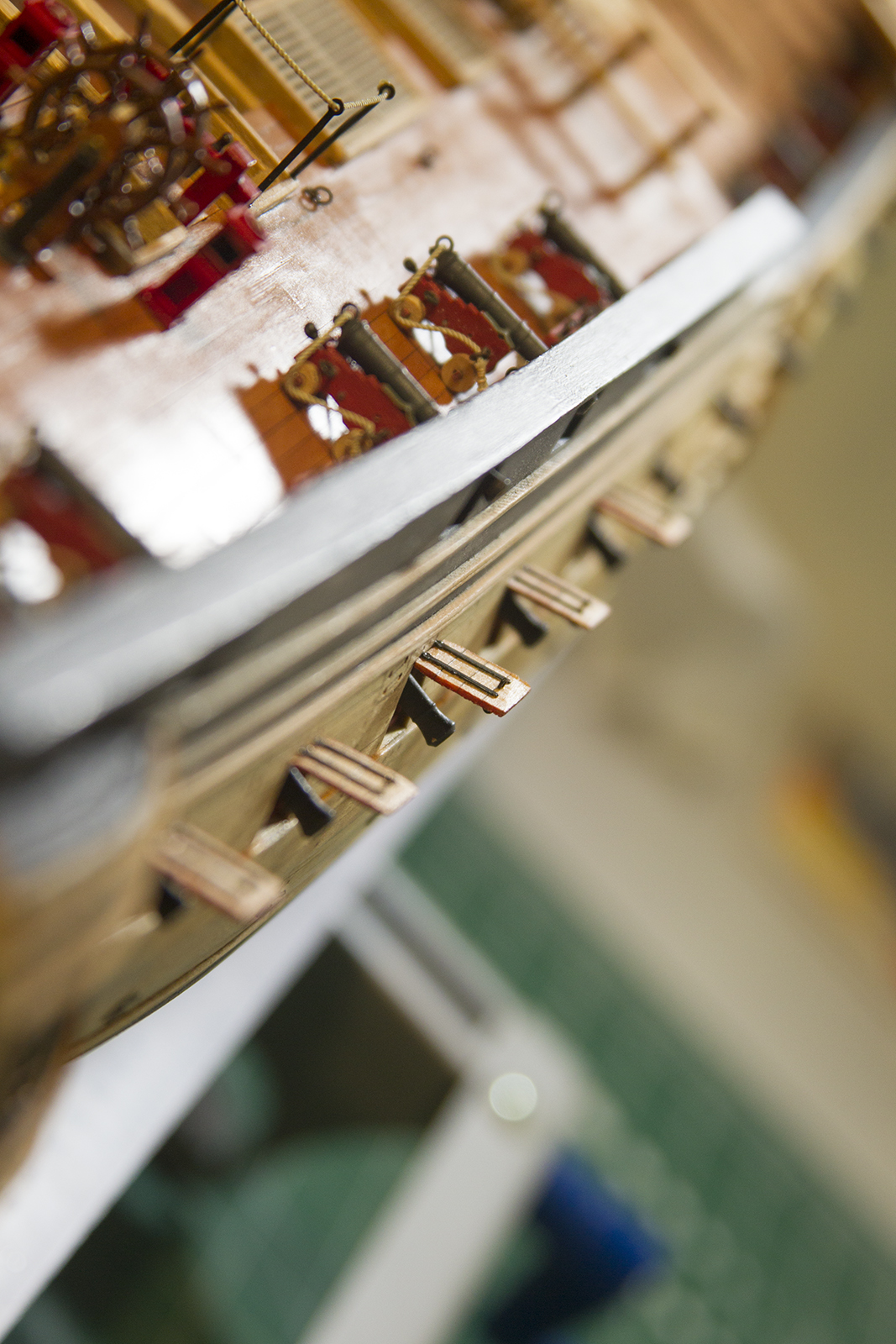
Assembly involves removing the trim on the side of the hull, mounting the chainplate, then fitting each deadeye into the grooves of the chainplate. The deadeyes are then held into place and braced with a series of “strops” – metal strips that extend to the hull and then are secured with nails.
Care must be taken to ensure that the deadeyes, strops, and nails are all placed evenly and consistent angles. Normally – the angles of the mounts would line up with the angles of the ratlines and shrouds as they extend down from the masts. However, in this case – there are now rigging lines as reference, so I lined them up as evenly as possible based primarily on aesthetic.
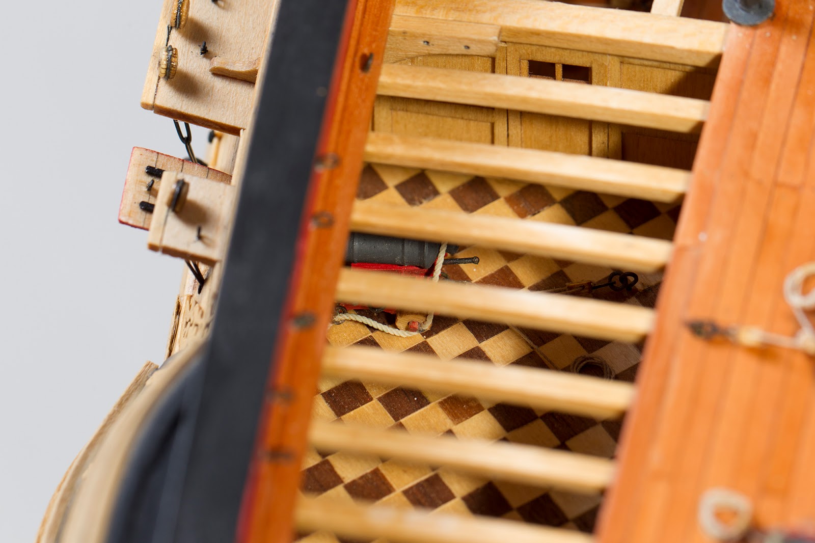
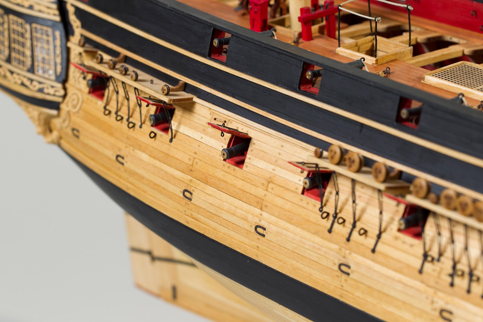
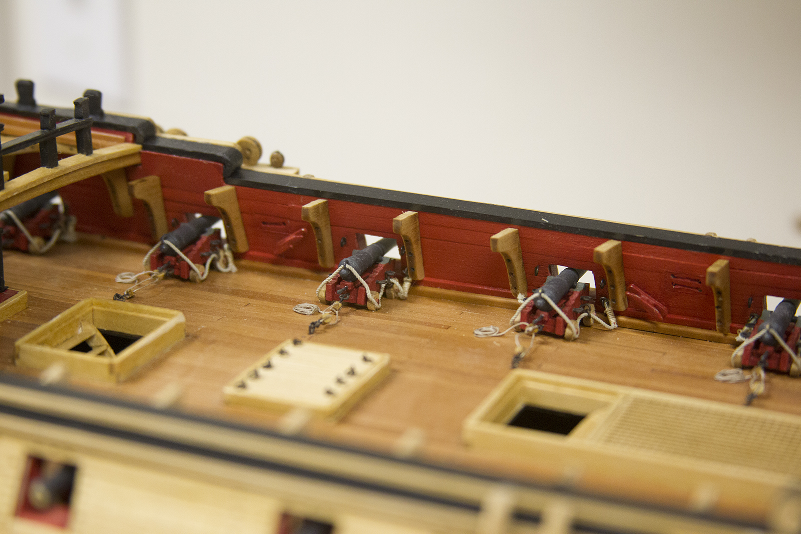
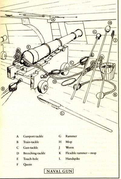
I’ve spent much of this building feeling as though the cannons are a bit bare. Most cannon rigging had three major elements:
– The breech tackle – a heavy rope threaded through the rings on the breech and fastened to the ship’s side on either side of the gun to limit its recoil. (Letter D in the diagram below)
– The gun tackle – one rig on each side, used to haul the gun into its firing position after loading. (Letter C in the diagram below)
– The train tackle – one rig that held the gun back and clear of the ship’s side while it was being loaded. (Letter B in the diagram below)
The kit instructions call for the gun tackles, although does provide for them as an option. Augie chose not to include them, which I fully understand. They require carefully rigging over a hundred single blocks complete with hooks and lines. Then, they become a challenge to mount to the eyebolts on the cannons and the bulwarks.
That said – I had second thoughts and started to go down that road. I rigged enough blocks and hooks for one side of cannons.
It was then that I realized, rigging the gun tackles for THESE guys – the cannon that you could see through the open deck, but couldn’t really get to – was going to be impossible. I made a few aggravating attempts, then after much profanity – bailed on the idea.

The alternative, if I still wanted to rig gun tackles, was to only rig the gun tackles on the accessible cannons on the open lower deck and open upper deck and leave the rest unadorned. I really didn’t like the idea of that kind of consistency.
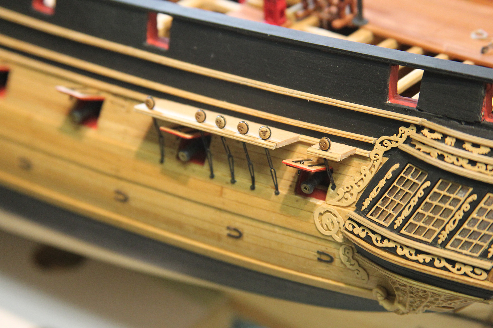
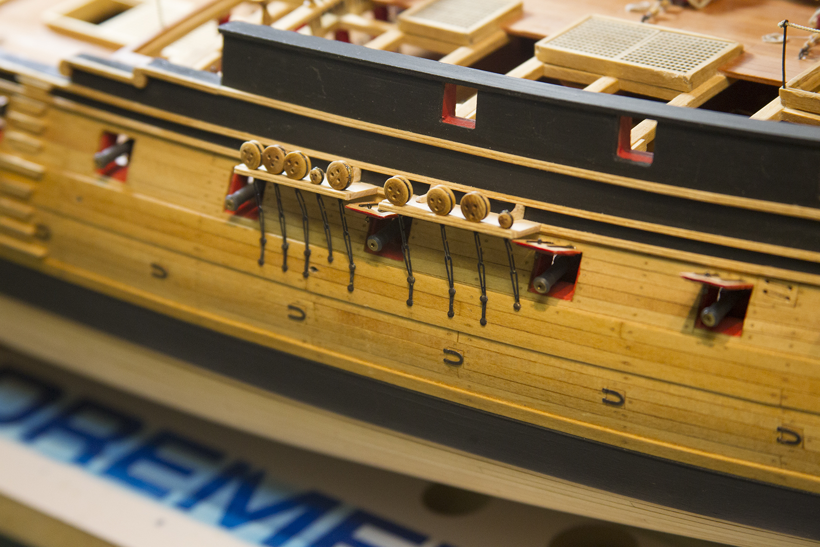
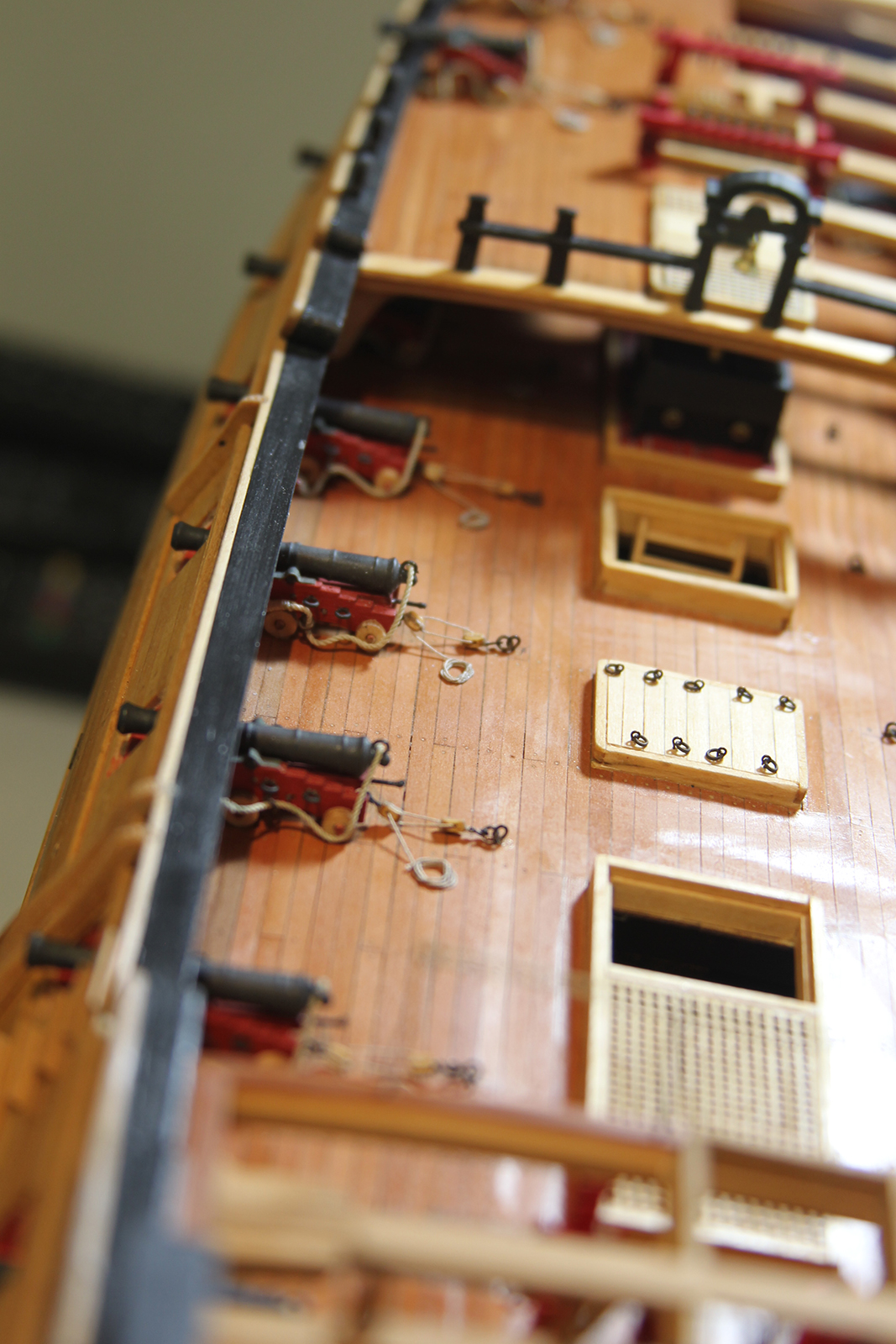
So instead, I settled on just rigging the train tackles. It gave the cannons a bit more rigging, which is what I wanted, and also incorporated the eyebolts mounted behind each cannon, which up until this point seemed to be begging the question “what am I here for?”

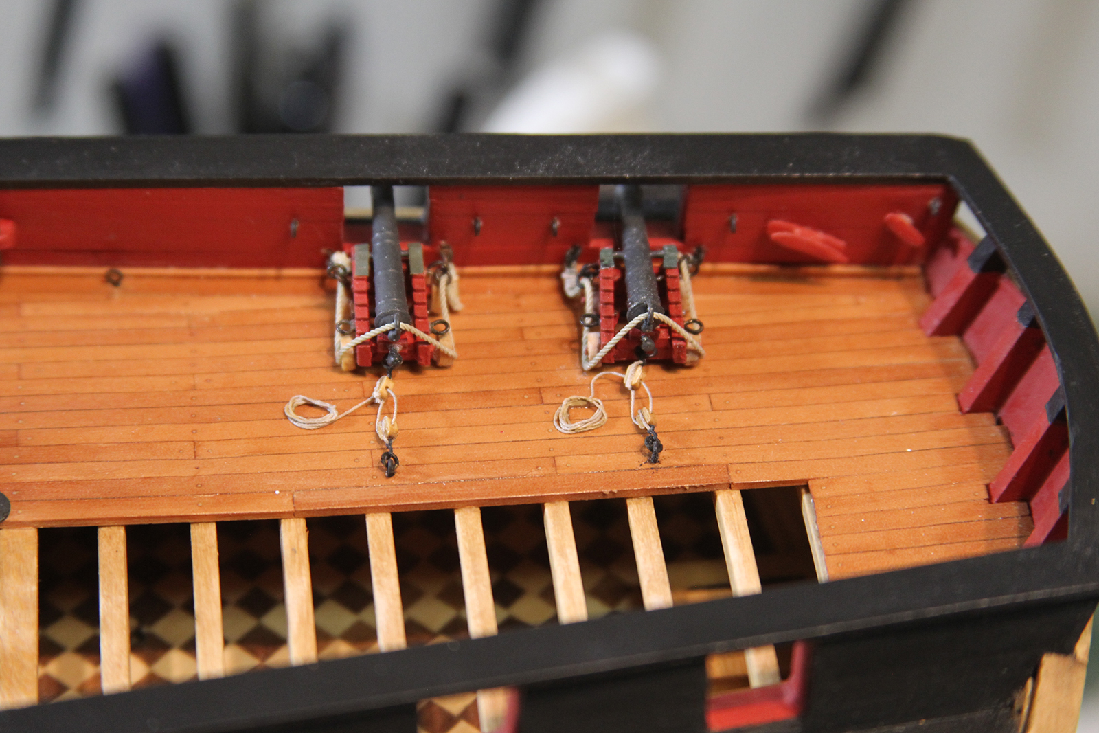
It was still challenging of course to rig the cannons that were on the second deck beneath the openings, but it wasn’t impossible. While it would be inaccurate for cannon’s to have train tackle (which is only used when the cannons are in operation) and not gun tackles – overall, I’m pleased with the look.
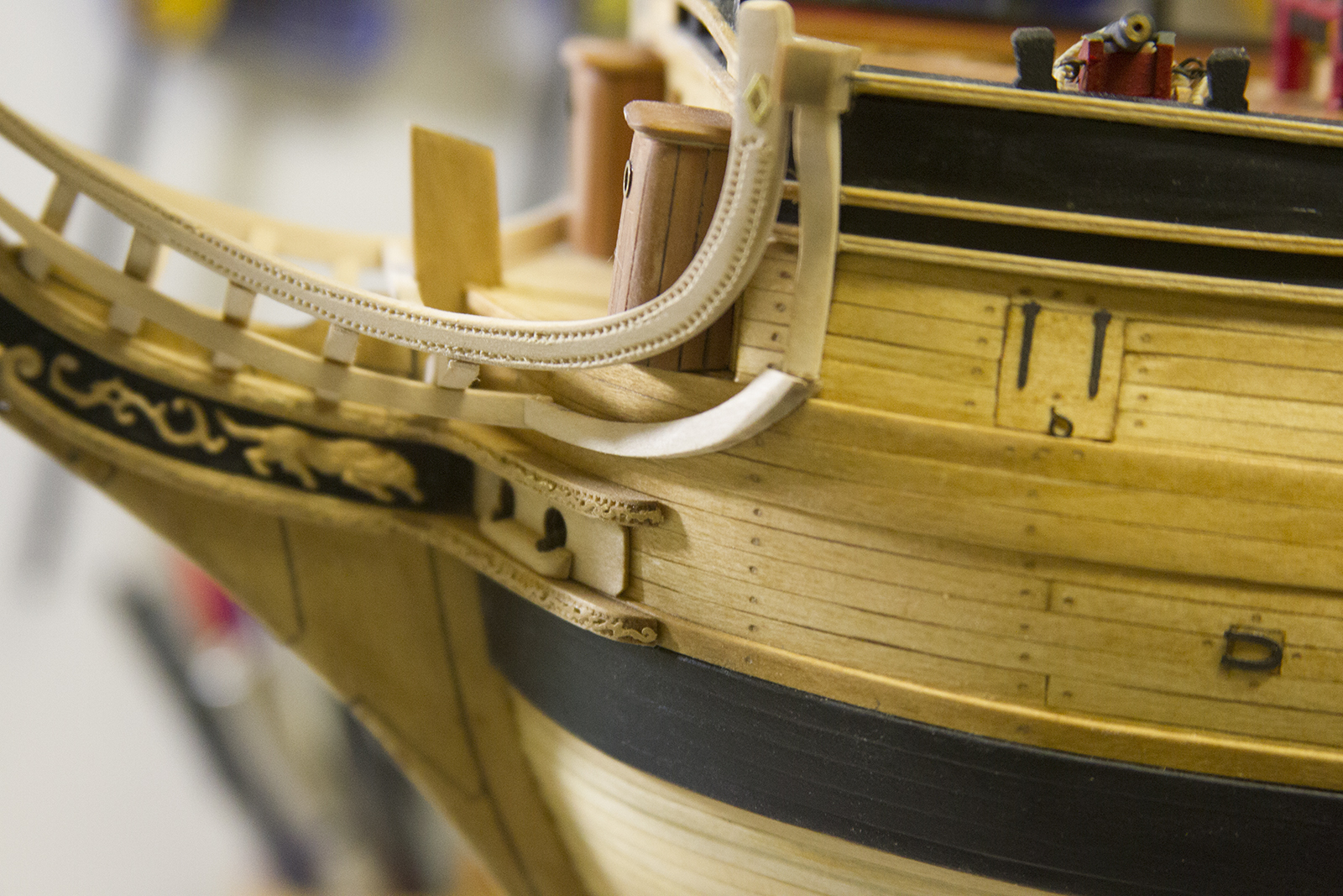
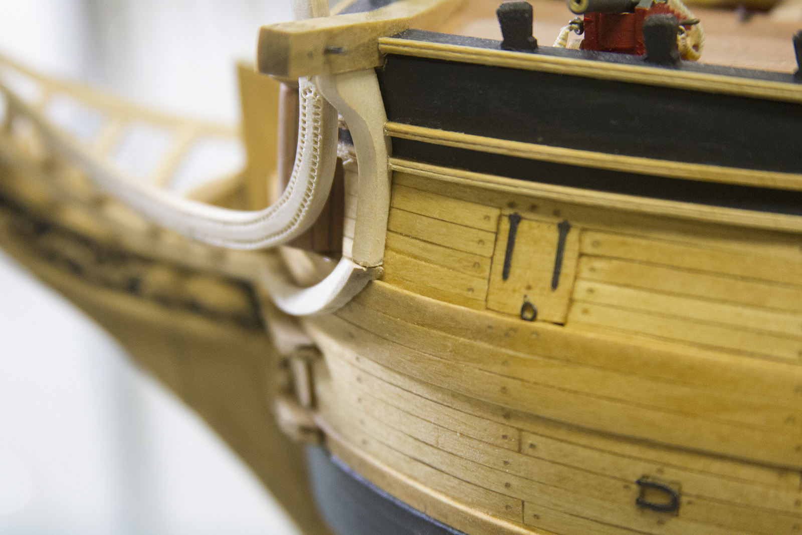
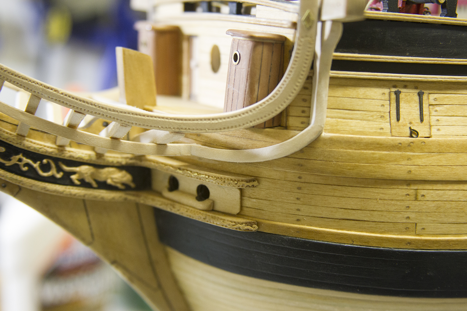
Down the stretch… and starting work on the out board hull details. Much of this will be repetitive, assembly line style work. I’ve found – at least for myself – that when I’m assembly a number of similar items, it’s always important to make sure I focus on each item individually to make sure they are precise and consistent.
The outboard work started with the boarding ladder, as well as the fenders and chesstrees. There wasn’t anything mysterious here, just measuring, cutting and sanding/shaping. I did find it much more beneficial to notch out the fenders to accept flush against the hull.
Next up – the gunport lids. I was initially confused as to the number of gunport lids that were required. There are 14 gunports on either side of the ship. Augie already had the most forward port closed off, with a cannon tied off on the deck. So initially – I planned for thirteen lids per side.
However, after examining the instructions and corresponding with Chuck Passaro (the kit’s designer), I realized that I only needed seven gunport lids per side, as not all the gun ports are “lidded.” As it turns out, having the extra lids became quite beneficial….

The lids were created by gluing four strips of planking together – after lining the edges with pencil lead to simulate caulking. The gunport lids are cut to match the sizes of the gun port openings, then carefully bevelled on all four sides. The beveling was extremely delicate even with the smallest of my needle files, and led to a number of “re-dos” – just one of the reasons I was happy for the extra lids.
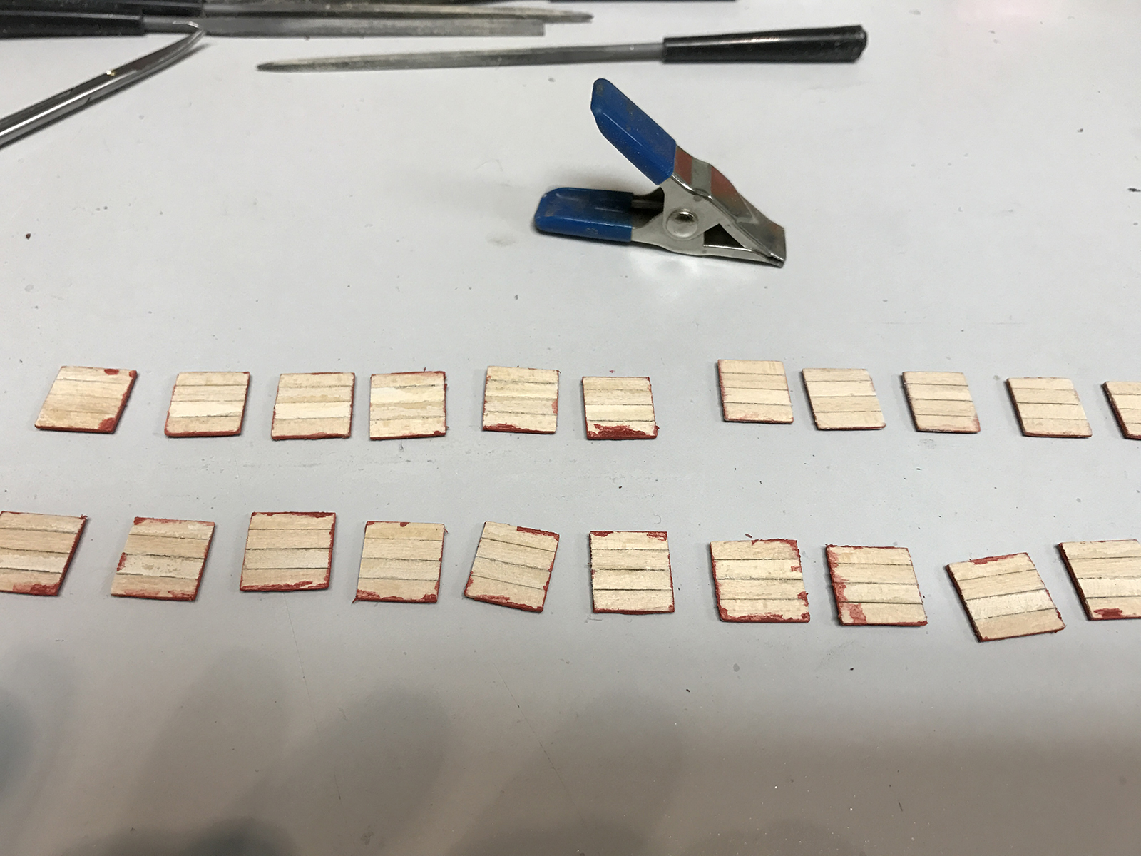
The lids were then taped down and painted with the same bulwark red used on the insides of the ship. And what a DISASTER that ended up becoming…
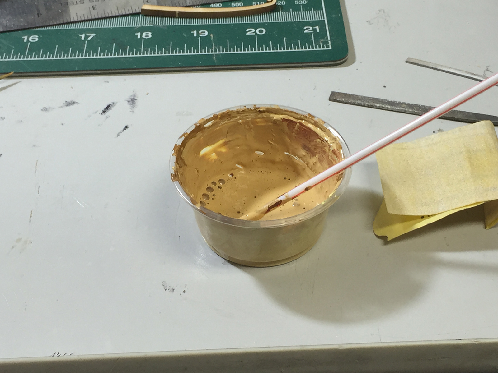
First off – the paint had not been used for a long time – since Augie had built the deck and bulwarks. So most of it was dried beyond use. Rather than try to make an exact color mix – which I felt was likely impossible – I decided to reconstitute as much of the paint as possible using water to dilute and a dremel and old bit as a high speed “stir stick.” Not only was this messy… but it was not super effective. The result… the red painted leaked and seeped into the sides and cracks of the wood of the gunport lids. *Sigh*
Trying to clean the lids just smeared the paint. I eventually recut even more lids, then sanded the tops and sides to get rid of as much paint as possible and clean them up for further assembly.
Further assembly:
Hinges and eyebolts are cut from the metal photo etched templates and blackened. Usually I’d use a mix of “Black-en It” to patina them, however it ended up being much easier to just paint. Two hinges and two eyebolts are added to each gun port lid.
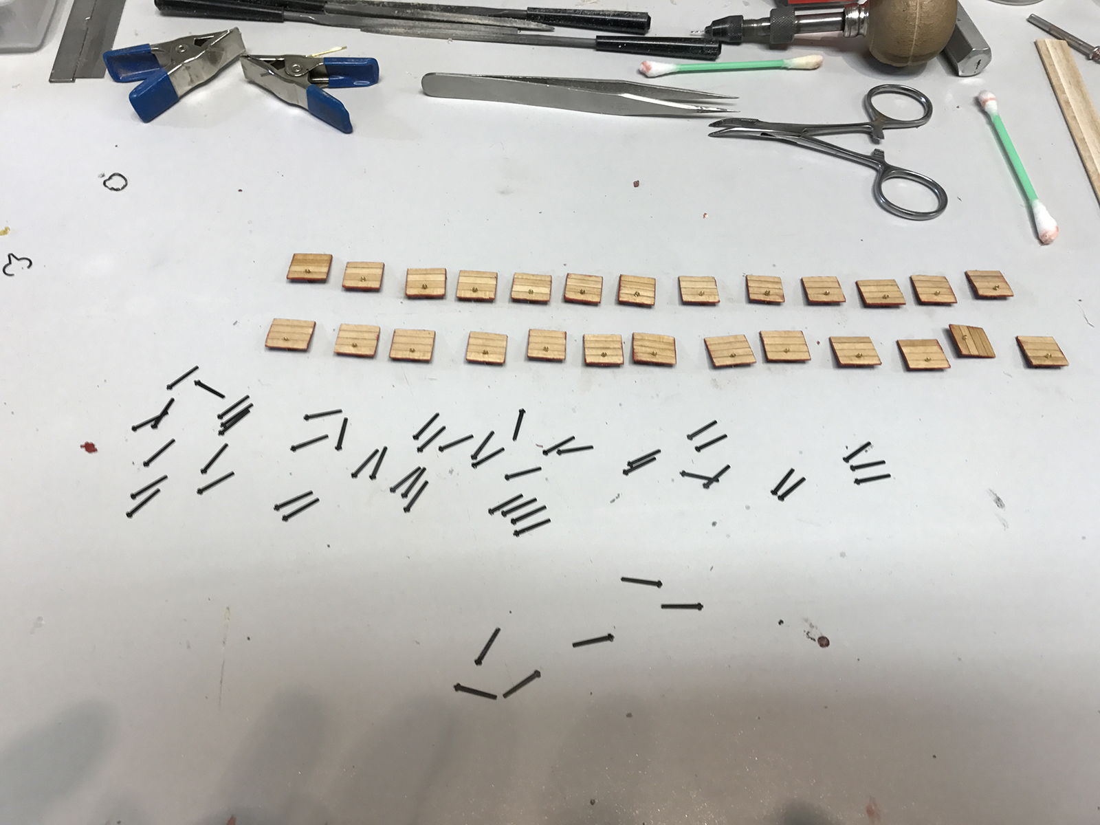

The gunport lids are each attached to the hull.
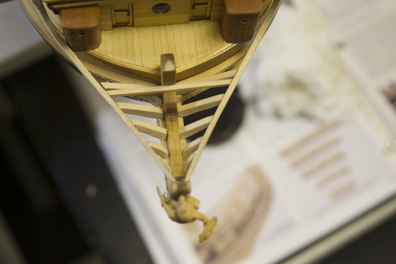
Once the headrails were all in place, etched and stained it was time to move on the the head grating and other finishing details to the bow. At first, the head grating looks quite intimidating with a number of cross beams, etc. But, with a little bit of patients, it went pretty smoothly.
The important thing was to measure each beam separately then install it separately. Even after measuring the distances and gaps, none of the beams were EXACT since the bow itself is very, very slightly asymmetrical. Not noticeably so, but enough that 1/2 to 1mm gaps are created if the beams are all pre-cut.
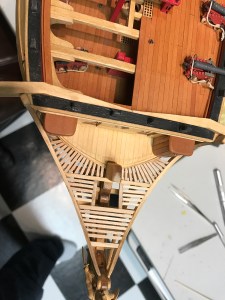
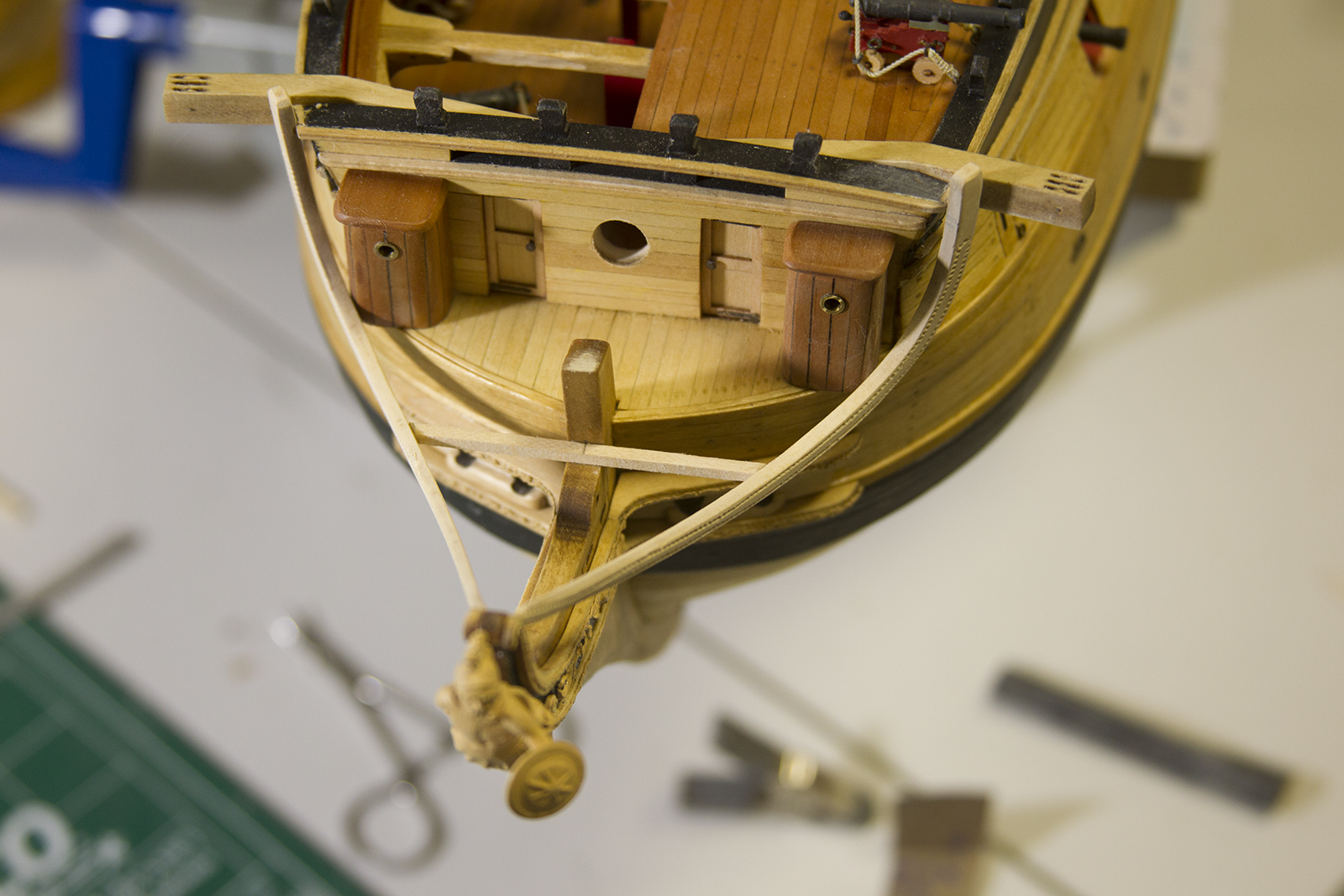
Once the head grating is complete, the “seats of ease” were up next. Of course, this is an elegant term for where the sailors “did their business.
The plans call for the seats of ease to be created using this plywood and precut seats. However, this was very, very challenging for me to get the sides of the seats to line up square. So I scratched that idea and decided top create my seats out of a solid piece then drill a hole into them. Obviously, this would make the seats much less functional, were a sailor two inches tall decide to use them – but plenty effective to simulate the look.
I cut a piece of extra trip, sanded it down, added the seat, then sanded the edges to match the angles of the roundhouses and headrails.
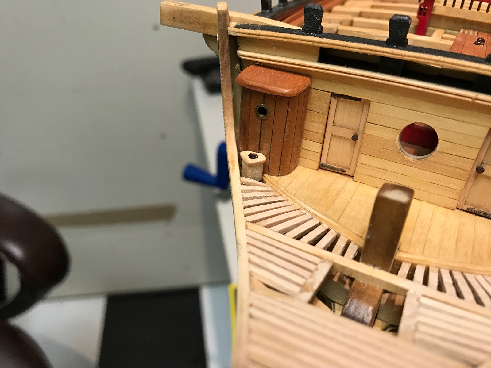
The false rails (the decorative, curvy rails on either side) are then added. Their primary purpose was to shield the sailors using the seats from the elements so they had at least a little peace.
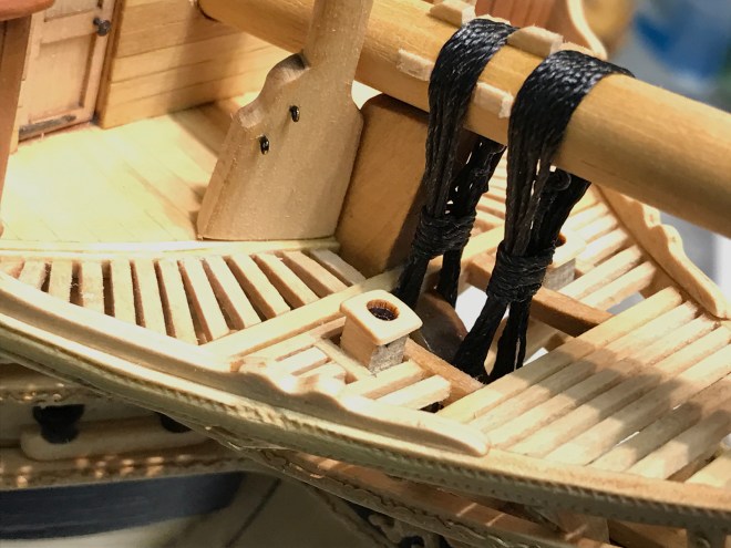
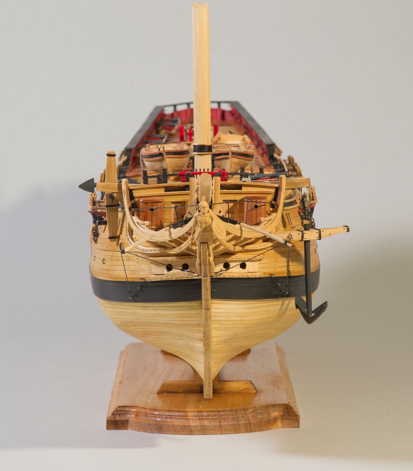
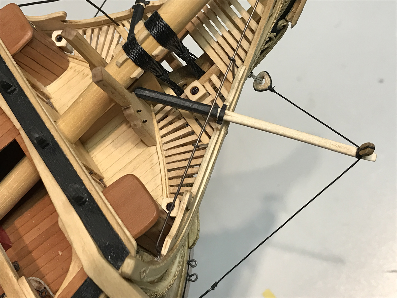
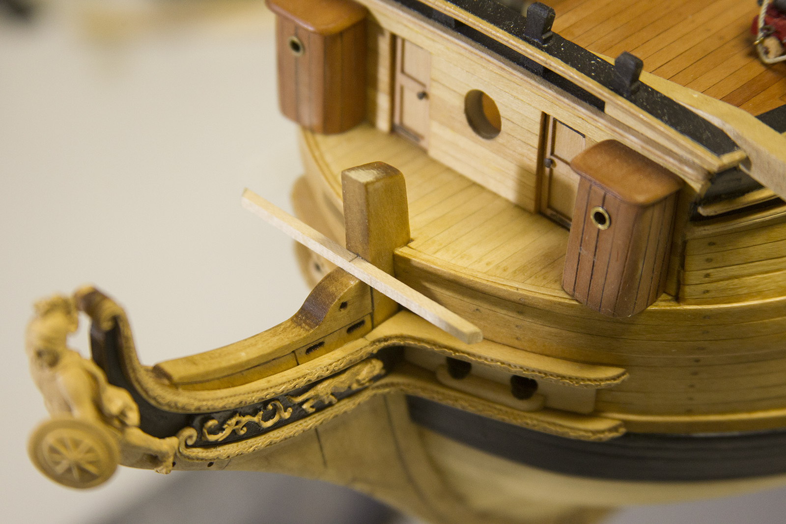
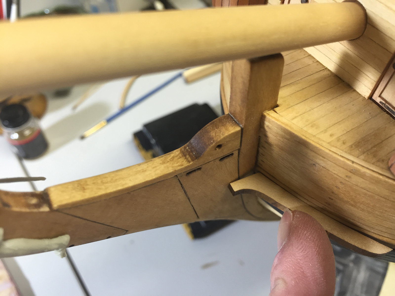
The two forward seats are added, then the bowsprit was permanently mounted as well. The two knightheads on either side took some delicate sanding to mount flush onto the bow, as well as accept the curvature of the bowsprit. Finally the bowsprit itself is attached in place with two sets of gammoning (the heavy rigging that wraps down through to the gammon hole in the keel).

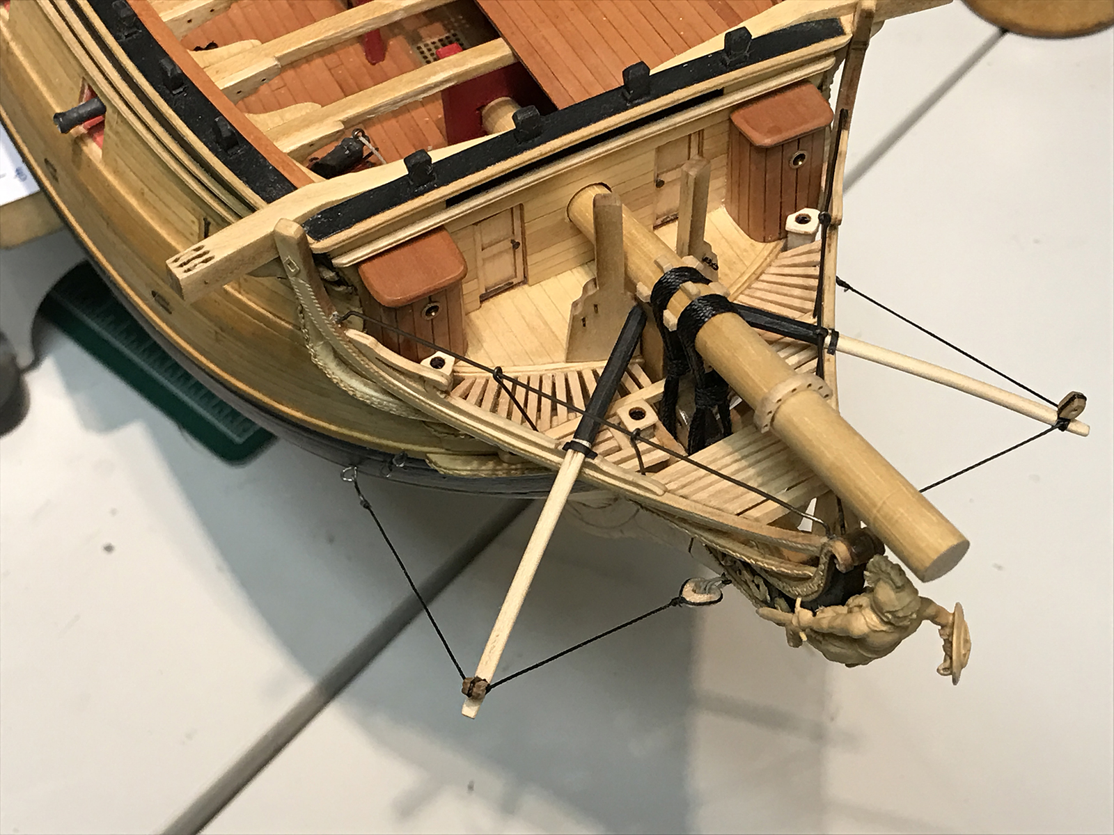
The two boomkins are shaped to meet the apex of the knightheads, then the inboard end is painted and mounted into place. They are accepted by notches in the false rails and held in place by a small capsquare. One single block is seized to the outer end of the boomkin and then secured to the hull using a triangular block.
Finally, the birthing rail (small metal railing along the bow) is added.
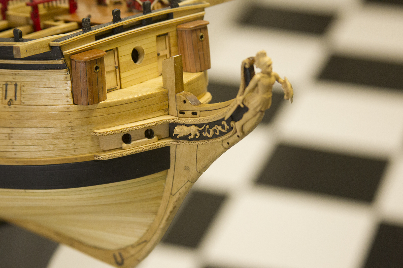
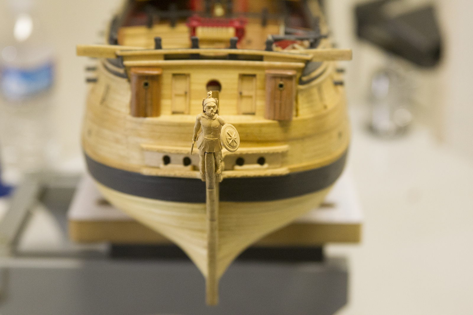
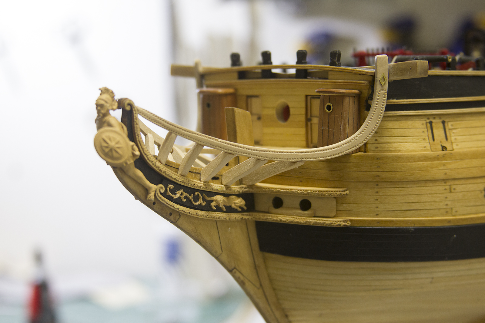
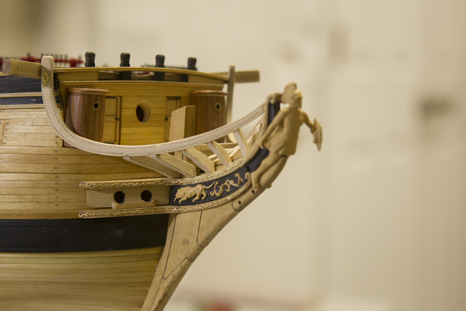
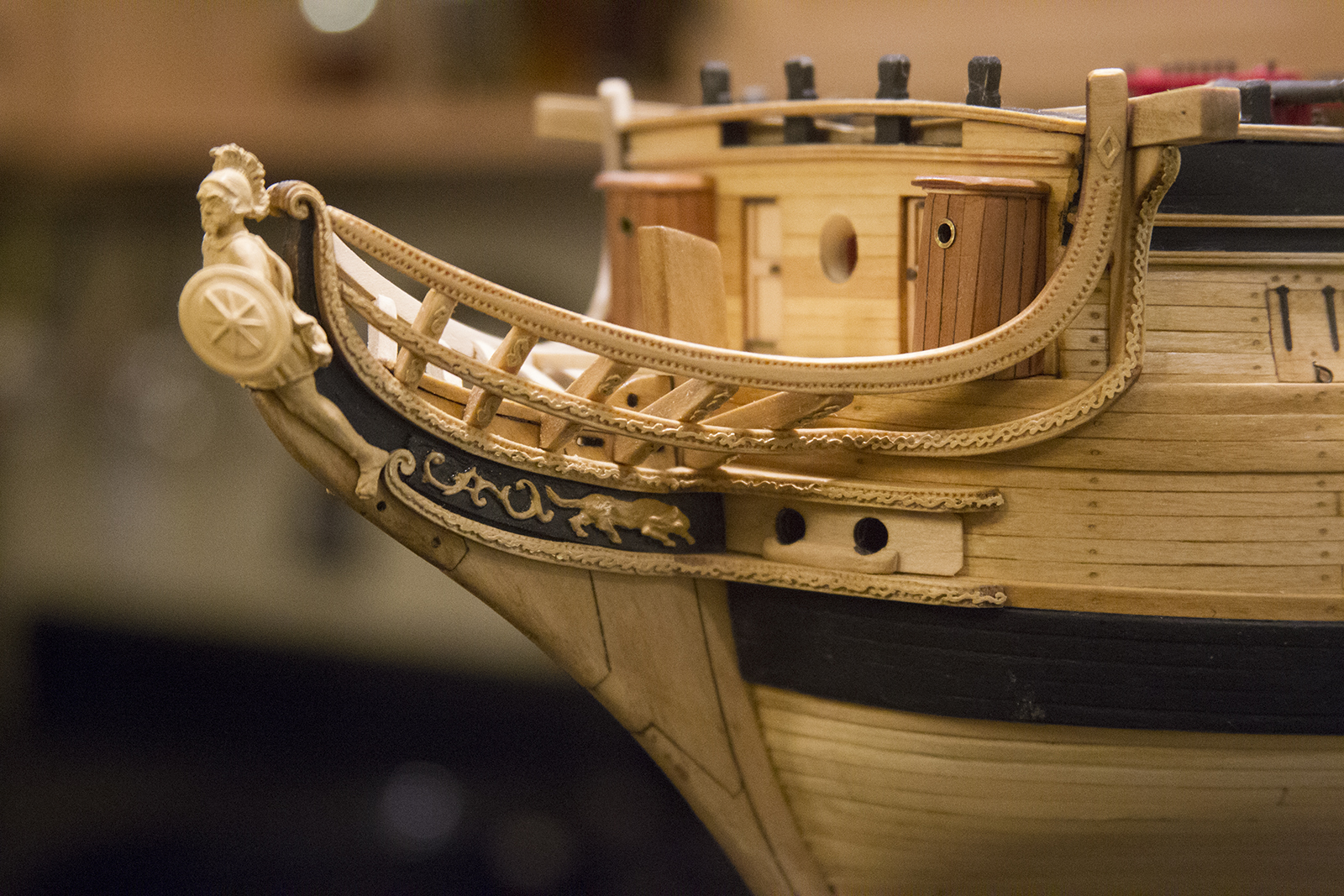
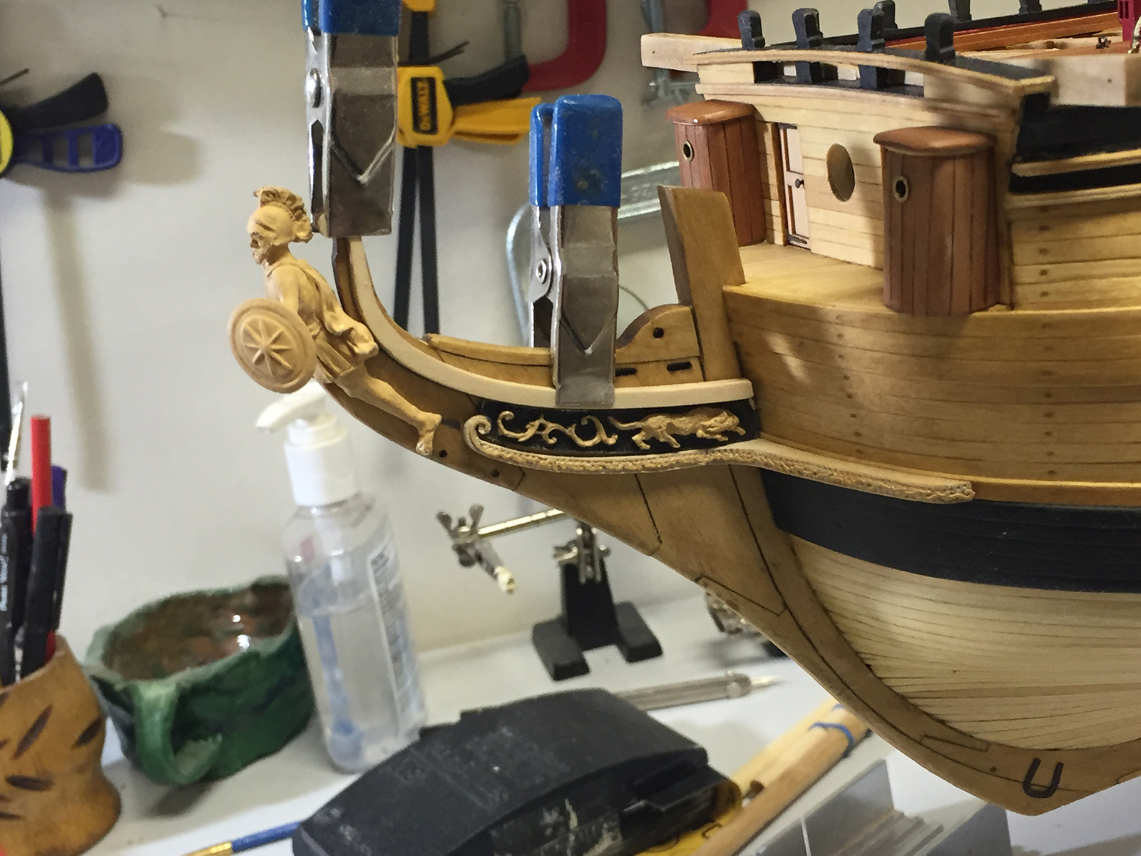
The main head rails and associated parts were up next, but first I needed to finish off the starboard side of the trailboards and decorative trim. The figurehead is (again) just placed in position as a measuring tool and will be permanently mounted later.
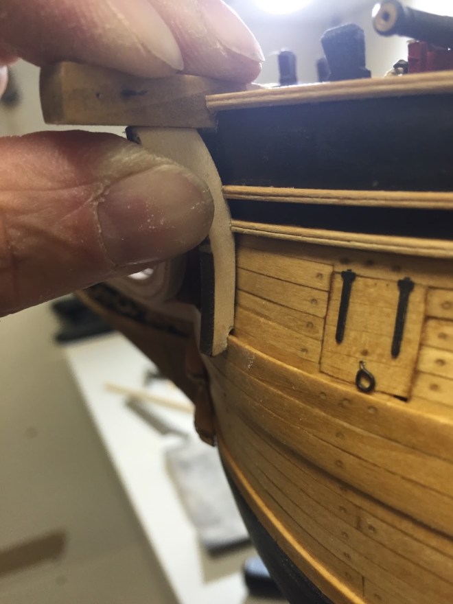
Getting to work on the headrails presented a couple of challenges. Obviously the port and starboard sides of the bow aren’t perfectly exact, so I needed to measure the head rails to fit, rather than specific measurements. In order to accomplish this, I installed the head beam first, so I had something to give me a frame of reference. Then, after thinning the head rails and tapering them, I encountered an additional problem at the fore deck of the ship along the rails… a gap.
Now, I wasn’t sure if I should taper the head rail, or if I should taper the ship. I was hesitant to do either, so my solution was to add a little bit of filler, then sand it to fit as nicely as possible.
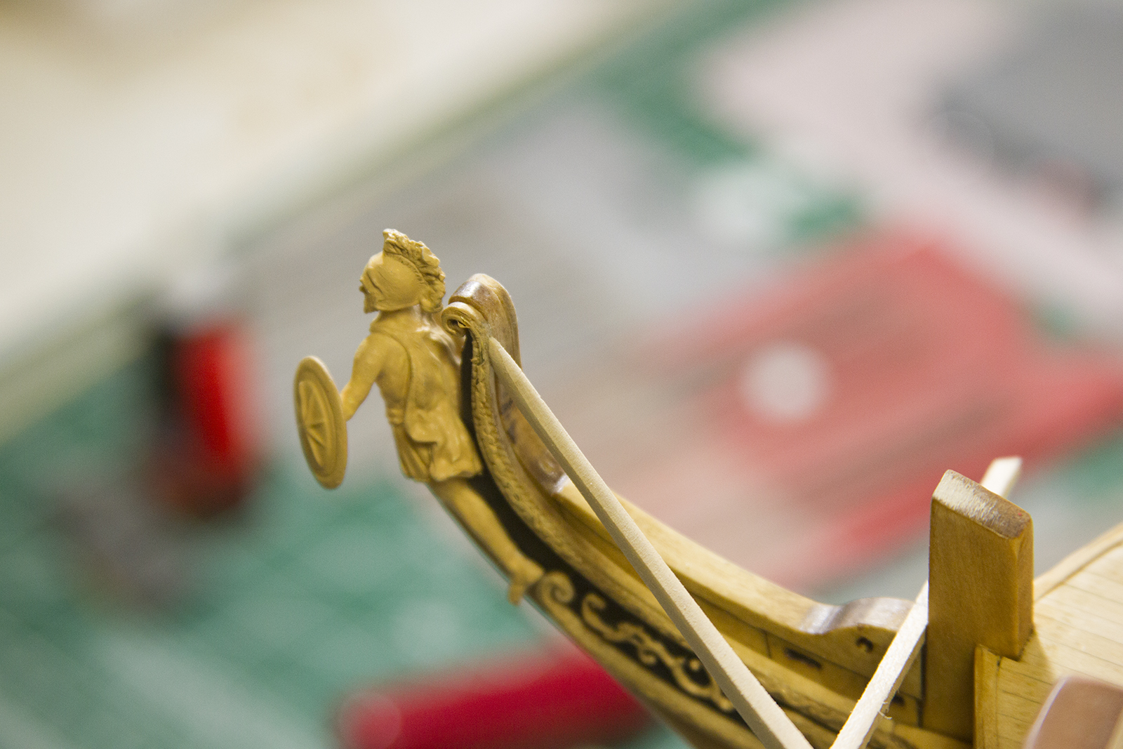
After getting the fit a smooth as I could, I glued the rails to the head beam, the sides of the hull, then bent the rails slightly to fit each to the foremost part of the bow near my mascot.
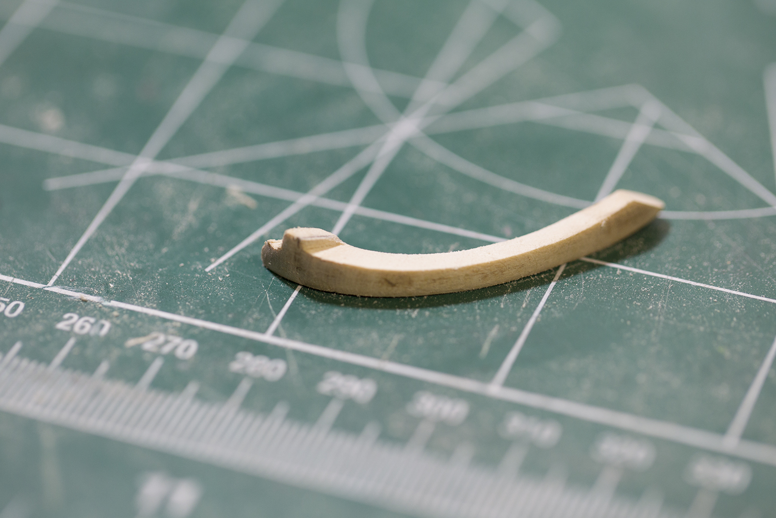
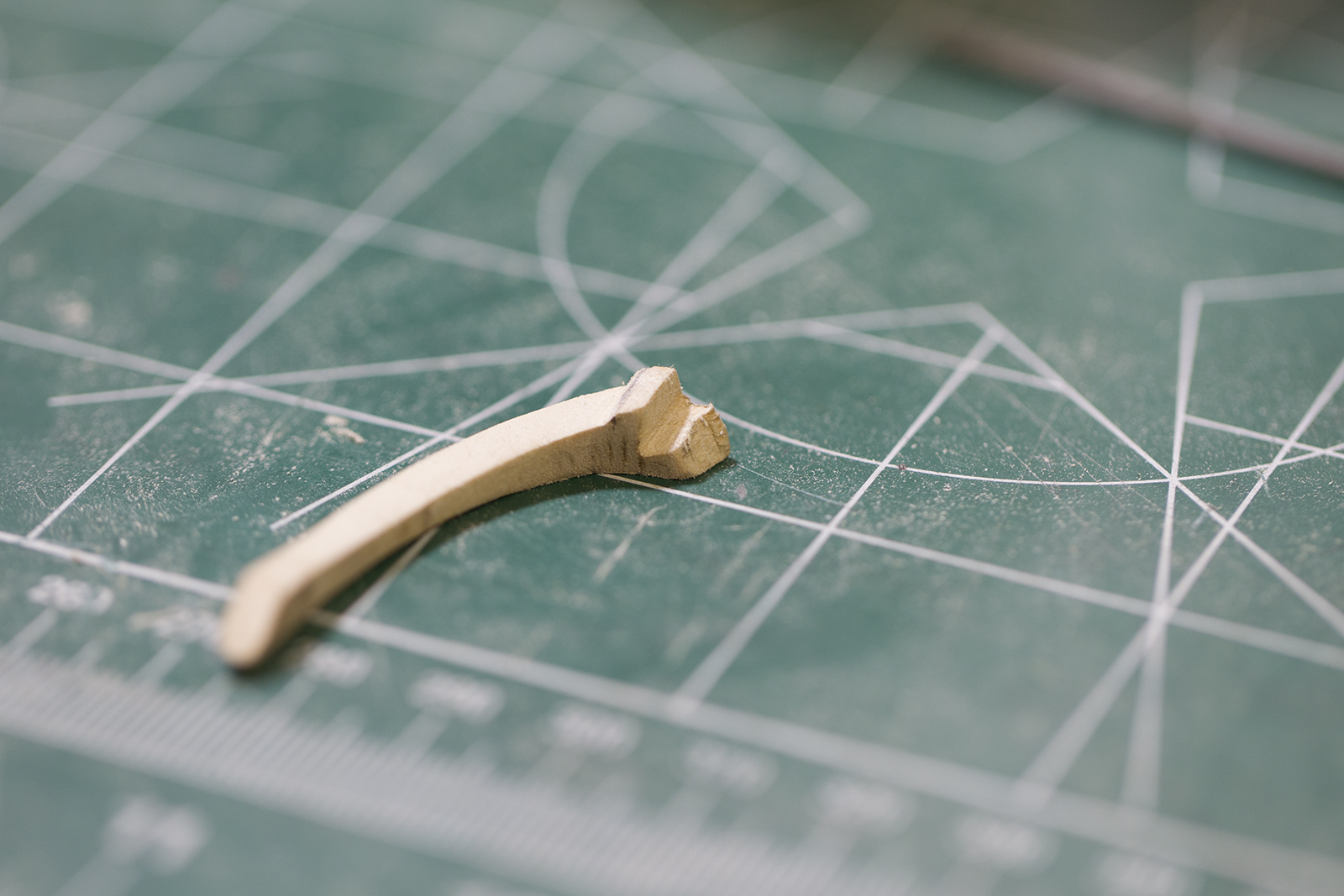
Next up, the head timbers that reach out from the fore keel to the head rail. These little buggers were by far the most fiddly parts of the ship so far. Although some reasonably shaped paper templates were supplied in the kit to measure the timbers fairly closely – they were of no use what-so-ever as the bow and head rails did not line up the way the plans would have suggested.
Essentially, this came down to trial and error. Lots of error. Each head timber was measured and sanded to fit individually. There were far more “misses” than “hits” before I was finally able to fit them in place.
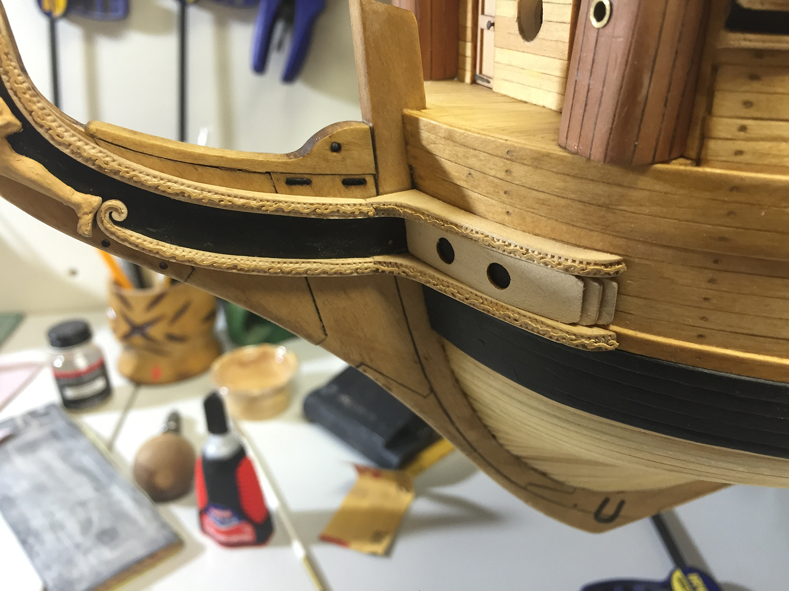
The cathead support knees run from the catheads down to the middle rail and must appear seamless the length of the bow. Understanding that truly ‘seamless’ was likely an impossibility (particularly with the light stain on the ship) I matched the pieces as closely as possible before just sanding them together.
Going from the support beams to the middle rail was a tough bit. Although the guidance warns against permanently putting the mid rail into position until everything is fitted – that didn’t work for me. I had to glue the mid rail in before I could measure anything out.
I started with the cathead knee, carving out a spot for it along the side of the ship and making an adjustment where the bottom meets hull.
However, I ultimately changed my methodology, and use the middle portion that links to the mid rail to the cathead knee as my focal point. I shaped and shaped and shaped some more to fit it along the hull, then notched out a spot against the hull where it would hopefully meet the cathead knee with as little deviation as possible.
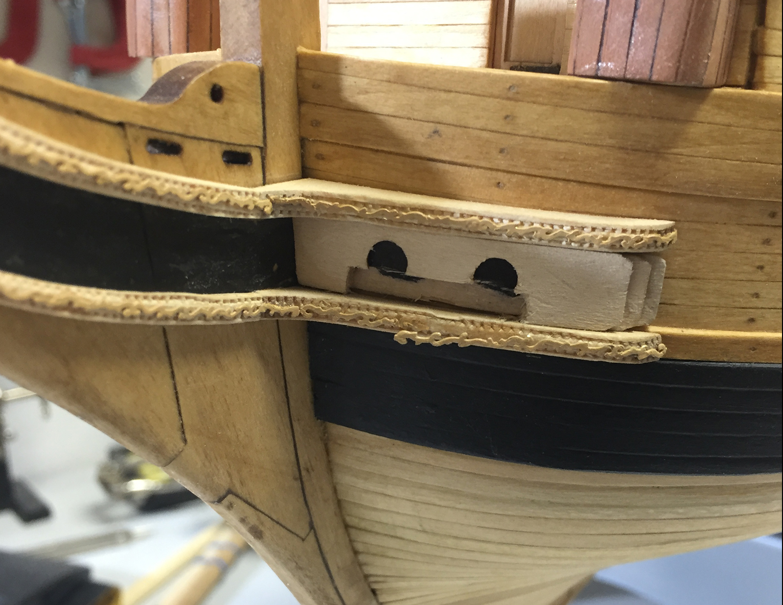
Here’s a good comparison of how the parts started, and the degree to which they needed to be shaped.
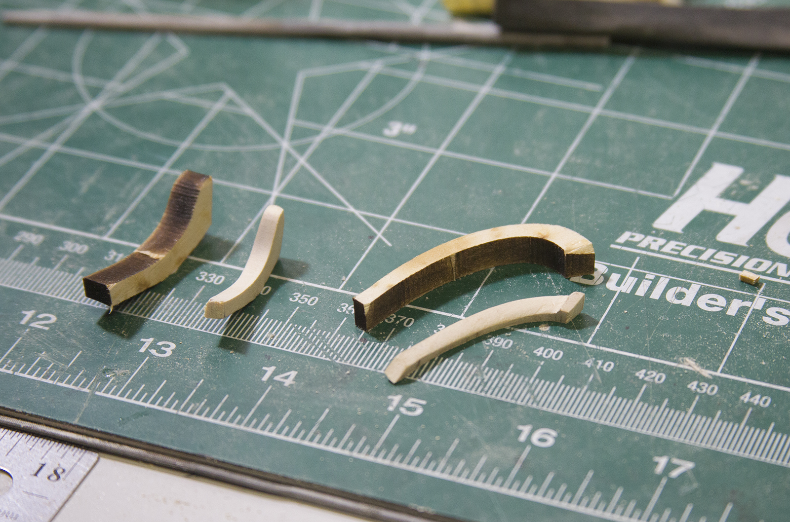
Once everything was aligned, it became a sanding fest a VERY small amount at a time until everything could get smoothed out. I also added a bit of glue to the cracks of the moulding so that as I sanded, the sawdust would get caught in the cracks and fill in the gaps as much as possible.
It was also important to sanded the moulding along the shape of the hull so the final product is the same width consistently throughout the bow. In the end, it was a bit of funky tweaking, and each of the pieces has a very slightly different shade to it based on the grains and the sanding. But overall, it smoothed out pretty well I think.

The head rails were “decorated” using a leathering tool as with the trailboards. Finally, I added the pre-stain and the stain, then touched up the decorative trim. Although the instructions only show the decoration to the base of the middle rail, I thought it more prudent to continue it the length of the middle rail.
I’ve got another trip this weekend. So, knowing I wouldn’t really get any ‘days off’ over the weekend, I decided to procrastinate some of my work during the week and head down to the shipyard and get some things done.
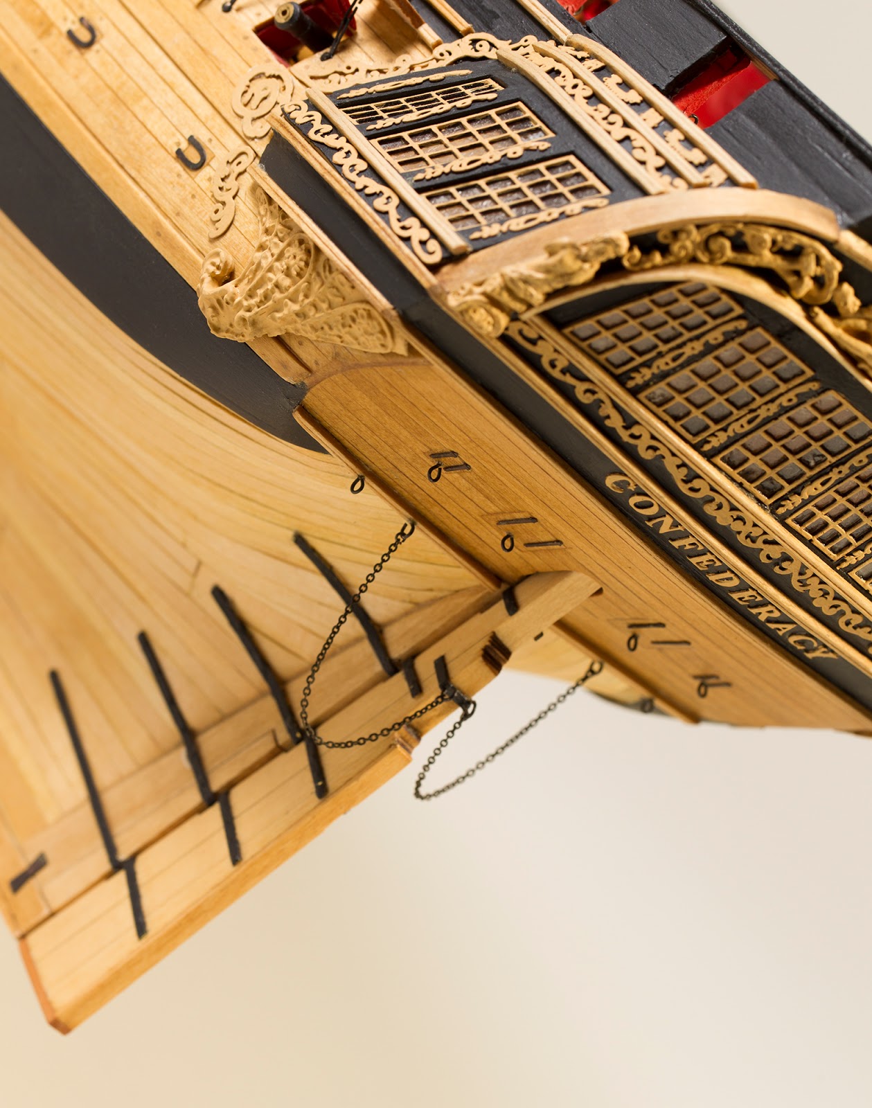
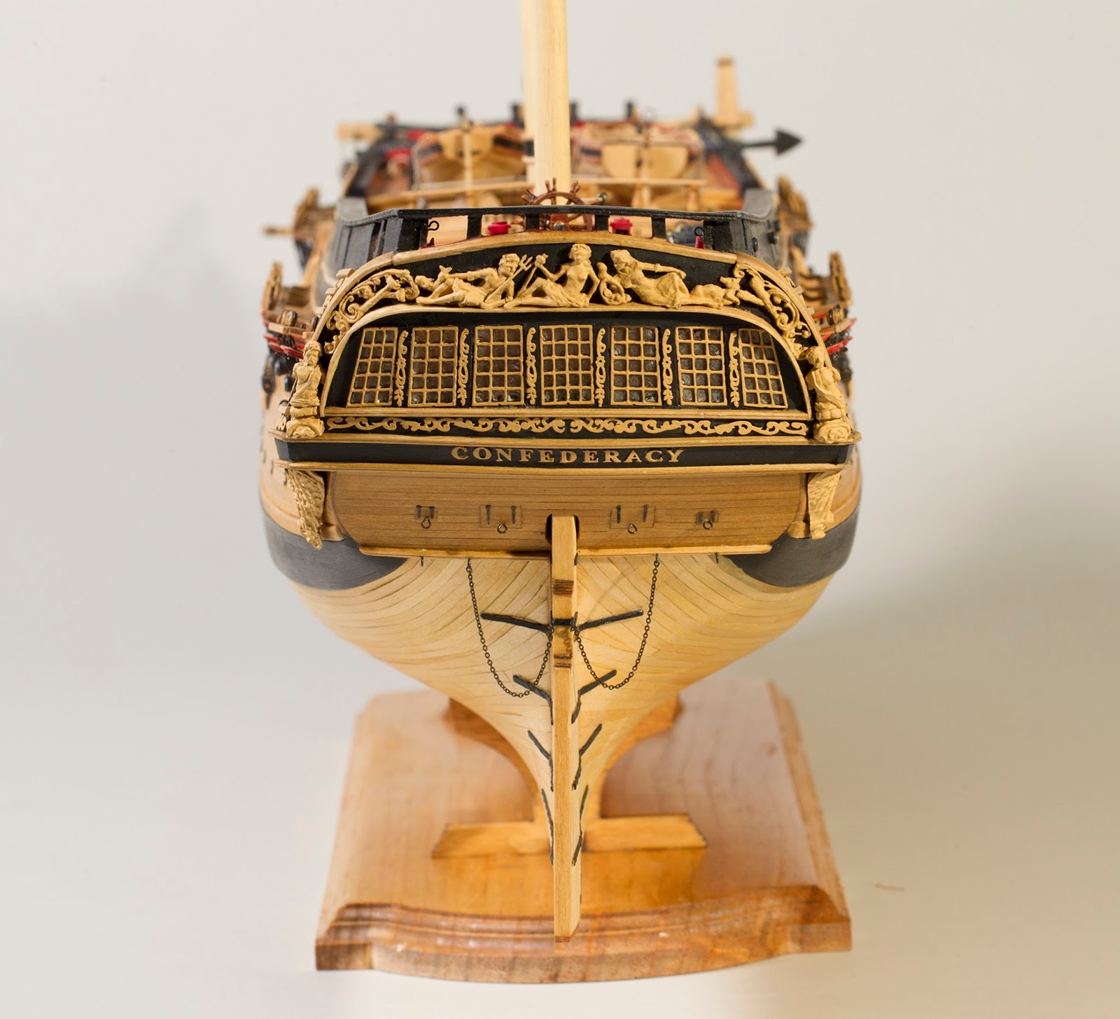
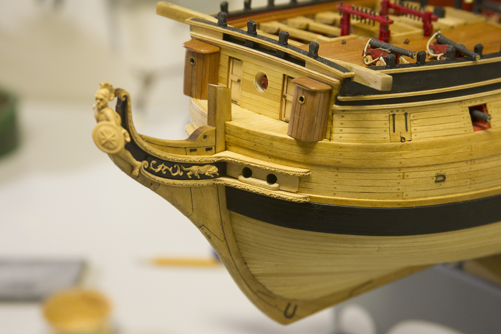
Next up, the cheeks, hawse holes and trailboards. Before I got started I did some fitting and measure, and prepping the figurehead etc. The first problem I ran into was paint color. The rear decorations and etchings of the ship were done is straight “wood” color from Testor’s Model Master line. Although it looked good, it is considerably darker than the natural stained color of the hull, etc. I liked this very much, as it made the details on the transom really pop. However, when we get to the bow of the ship and painting those etchings and even the figure head that dark – it just didn’t look right.
After some experimenting, I was able to come up with a pretty good color with about a 60/40 mixture of “House Cream” and “English Oak”. Of course that meant repainting all the etching and window frames and details on the transom. I was NOT looking forward to this… but necessary is necessary and I spend three days with a size 0 brush while my eyes crossed and my fingers cramped. ;p


As a side note – I had to add a good coat of primer to the figurehead to get it to take the paint. Remember, we swapped out the metal figurehead with the plastic molded one. Then, the cheeks. Very light sanding to get rid of the char, then a bit of reshaping to get them to fit to the bow snuggly.

No alternatives for the photo etched carved strips, so they required some careful painting. I fitted them first to get an idea of what part of the bow needed to painted black, then did more painting.


The instructions call for some etching along the cheeks my gauging out lines on the sides, then smoothing them out. But I found this little tool in my stash and thought it’d look pretty cool. Overall, I like the way it came out with the metal laser cut etching painted and attached.


My next problem occurred when I dry fitted the hawseholes and trailboards. The directions call for four pieces shaped to fit the bow of the ship. But, after only three, I was running out of room quickly. And bear in mind, I BARELY sanded the backsides of the cheeks. Just enough to get rid of the char and adjust the “roundness” to fit the bow ok. Oy.This wasn’t going to do. So i stuck with three, and fitted the bolster. NO CHANCE any of this was going to fit.

My first solution was to create and inset in which the bolster would fit. After a number of different attempts, this failed miserably. So, my final solution was to just have ONE layer of the trailboards and fit the bolster and drill out the hawseholes. Overall, I think it’s definitely passable. All of the basswood is treated the same as the rest of the trip with a layer of wood conditioner, stain in Miniwax “Natural” then I’ll add a layer of lacquer. Ultimately, this as made the etching and wood pretty close to the same color.

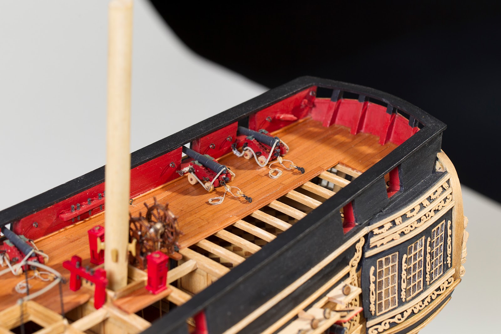
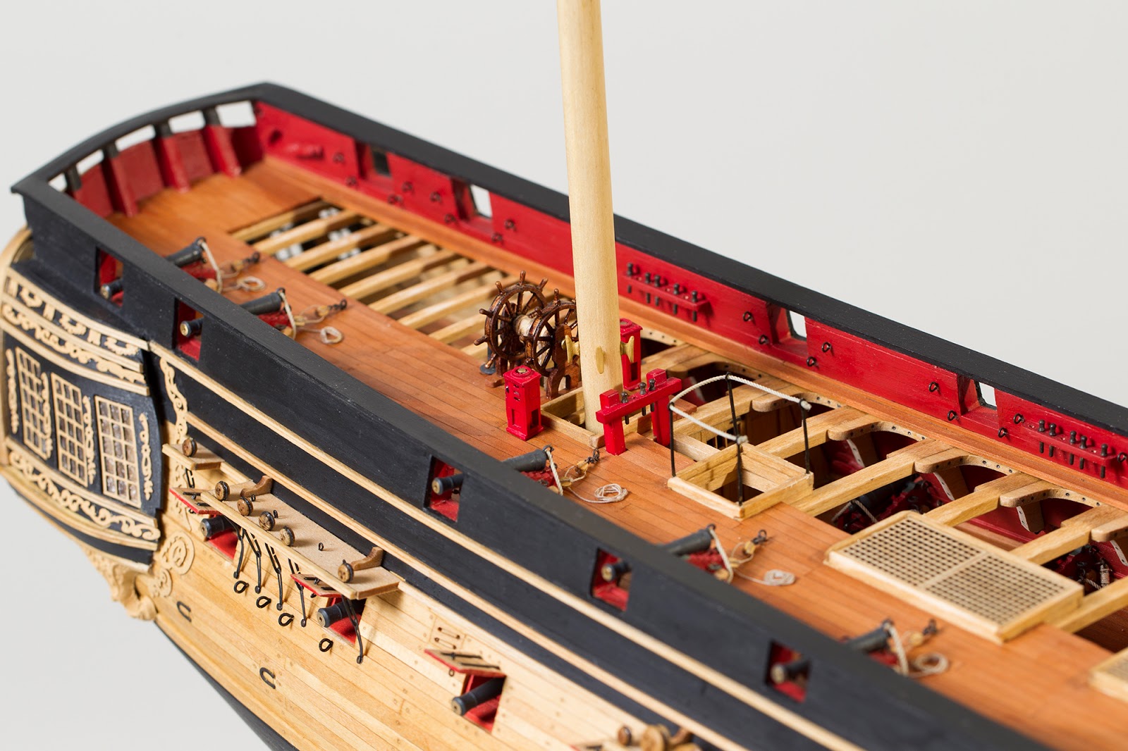
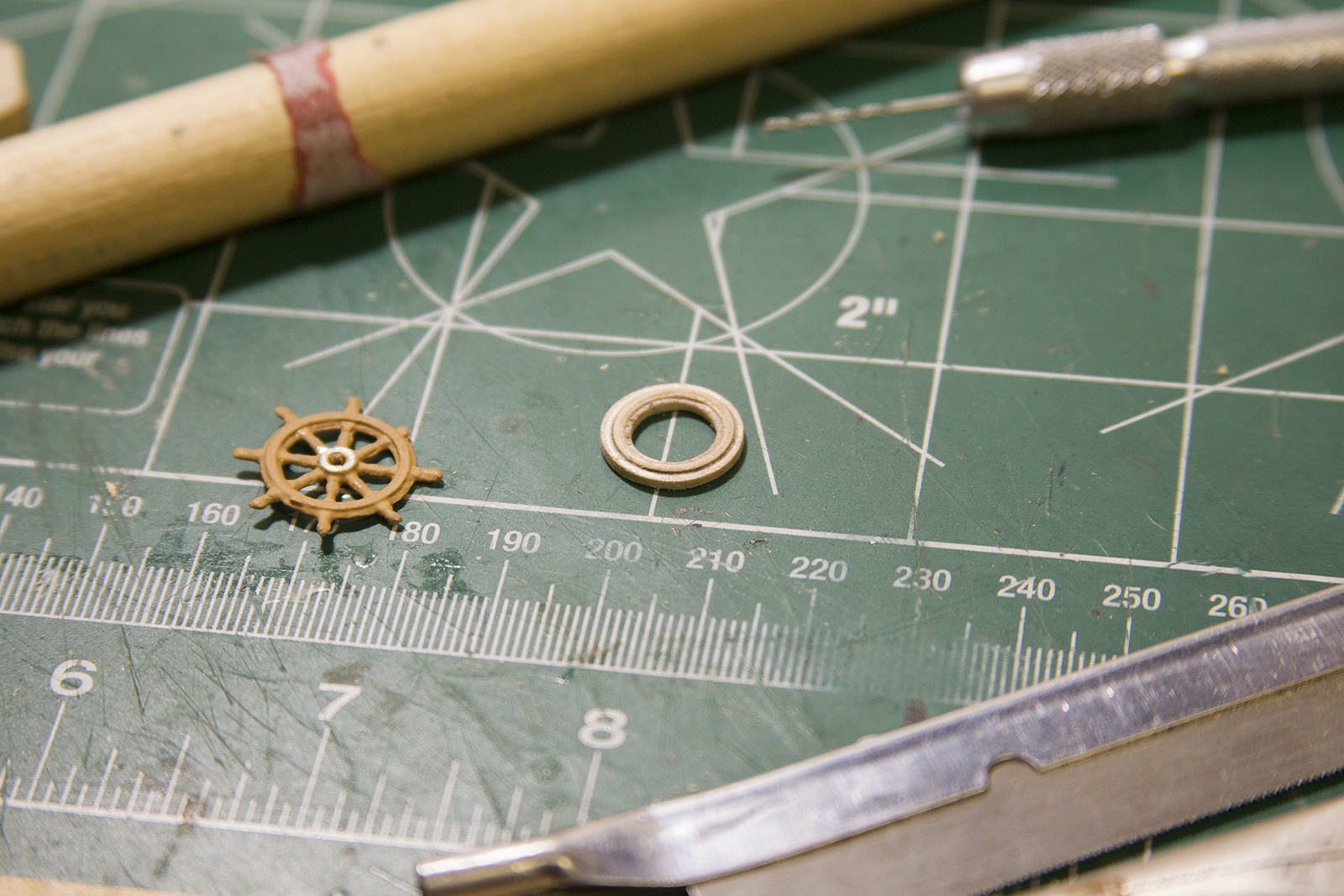
Although I was quite happy with the ship’s wheels that I’d created by hand SEEN HERE, when I got a look at the new ship wheel kit created by Chuck Passaro for his supply store Syren Ship Model Company, I knew it’d be perfect for the Confederacy.
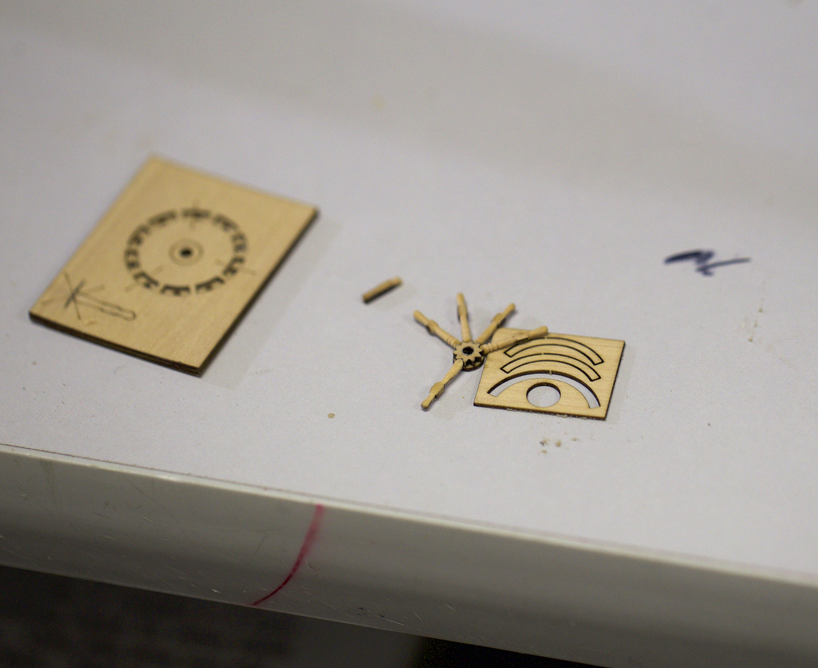
Chuck’s instructions for the wheel can be found HERE, so I won’t go into full detail. But, the kit comes with 29 laser cut pieces that eventually come together to form the wheel, along with small “jig” used to help in the construction and measurements.


First, the two sides of the halves of the jig are glued together to form slots that are precisely spaced. Small laser cut blocks are detached and sanded. However, as Chuck insists, the sides must remain precisely measured; so only the top and bottom are slightly sanded to get rid of the laster cut char and fit into the jig snug but not tightly.


Once the blocks are fitted in the jig, they outer portion of the wheel is glued into place. This creates gaps in which the spokes will fit.
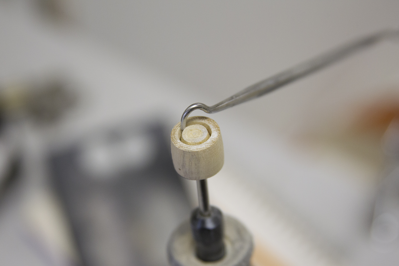
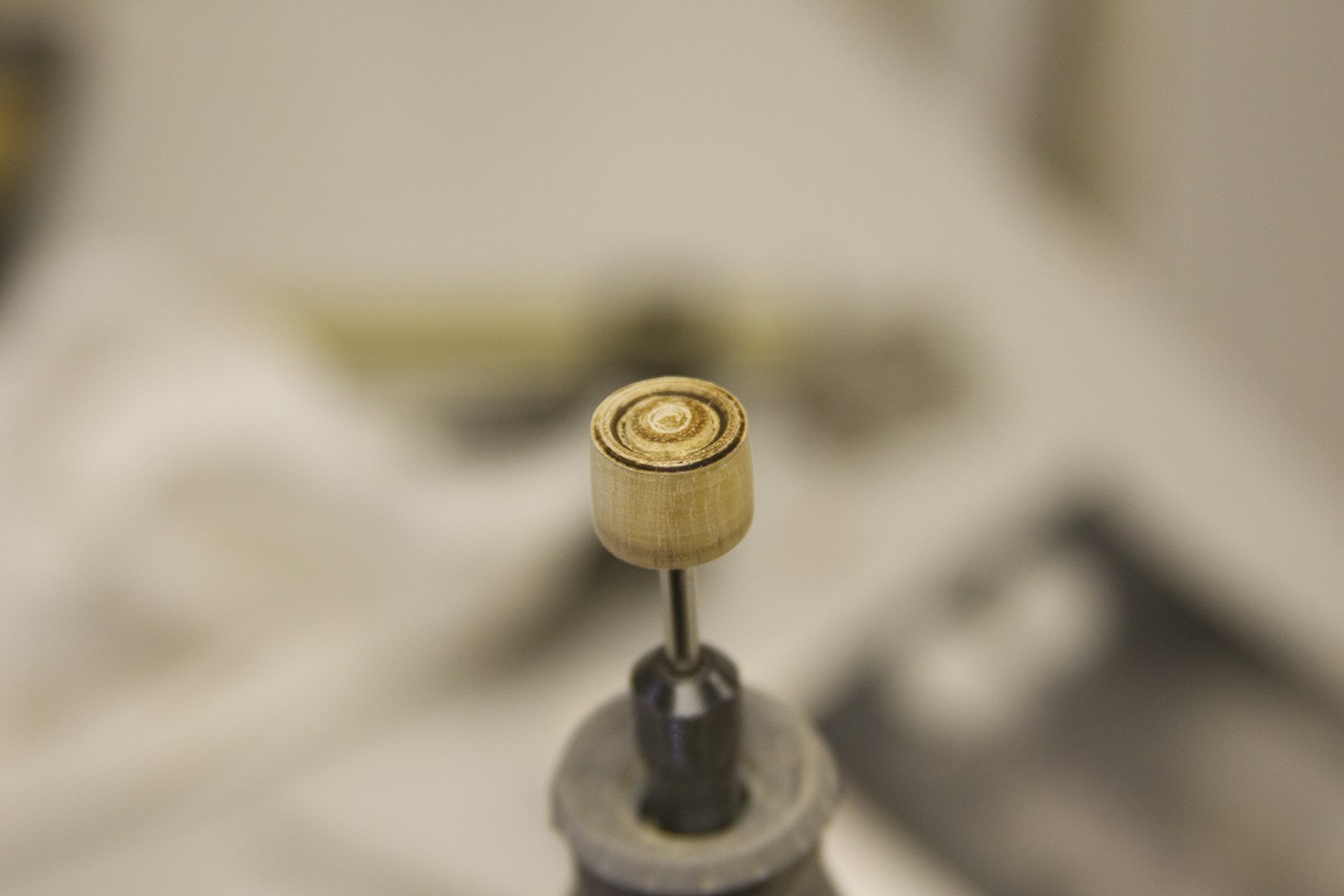
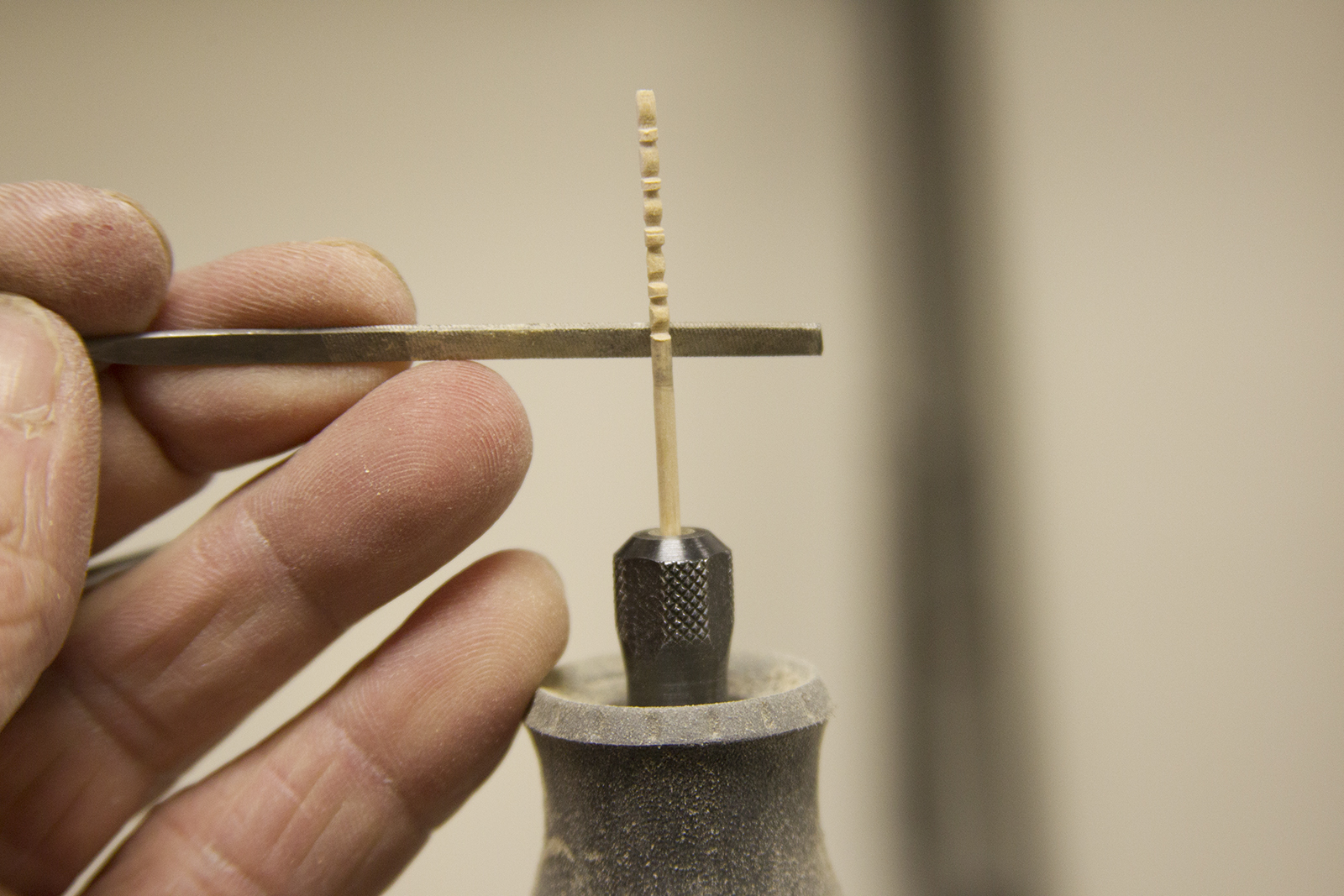
Next up, the spokes – which are the most delicate part. Each spoke is laser cut with square edges. To round the edges, the spoke is mounted in my Dremel, which is in turn mounted vertically in a vise. Each spoke is just an inch or so tall and tapered from about a millimeter thick.

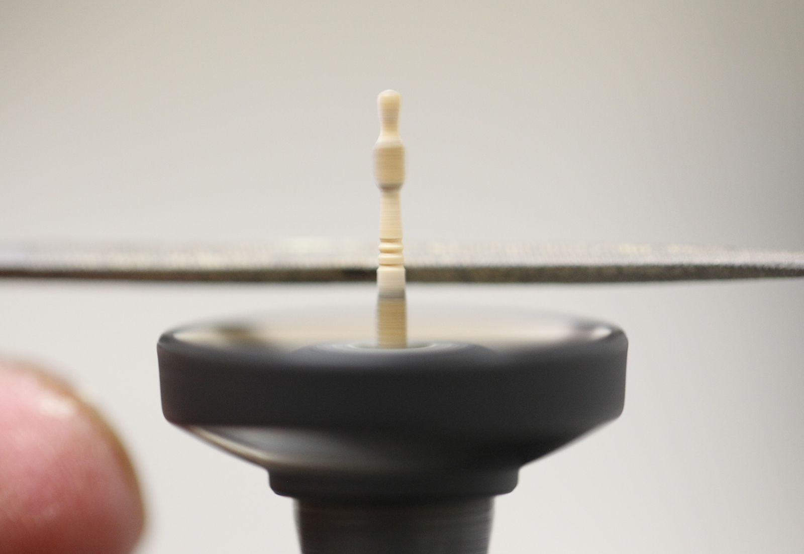
The Dremel serves as a lathe, and the spoke is shaped and ultimately detailed. I decided to get a little creative and documented the process in a YouTube Video.

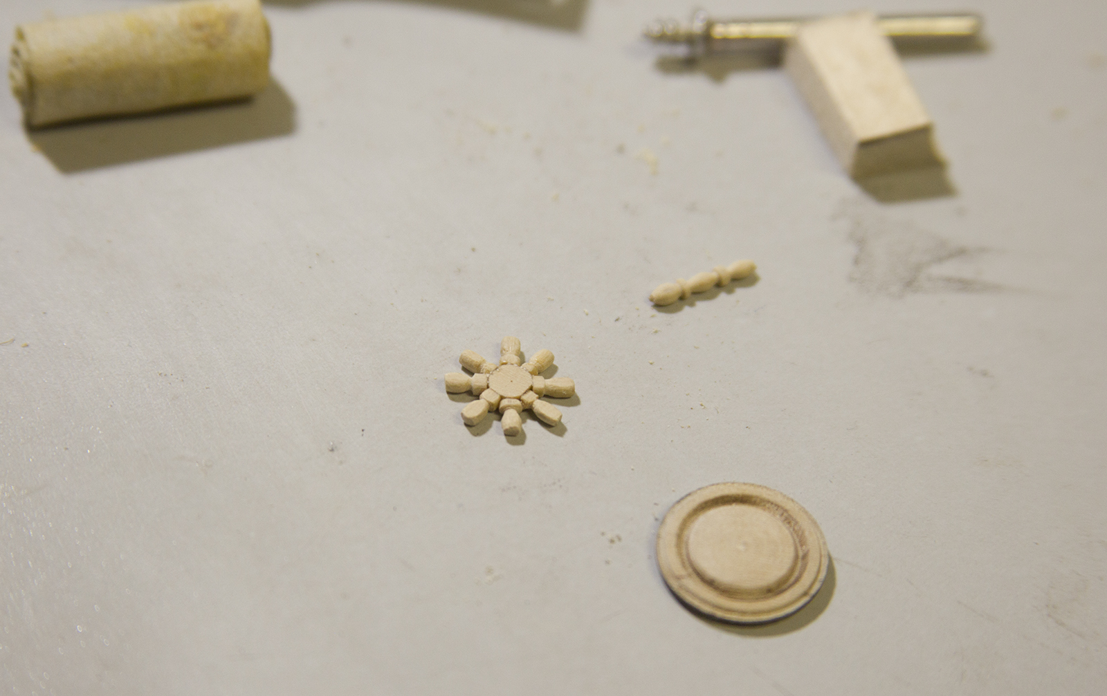
The spokes are place and glued around the center core of the wheel, placed in the jig with the square portion of each spoke fitted in the slots created by the blocks.

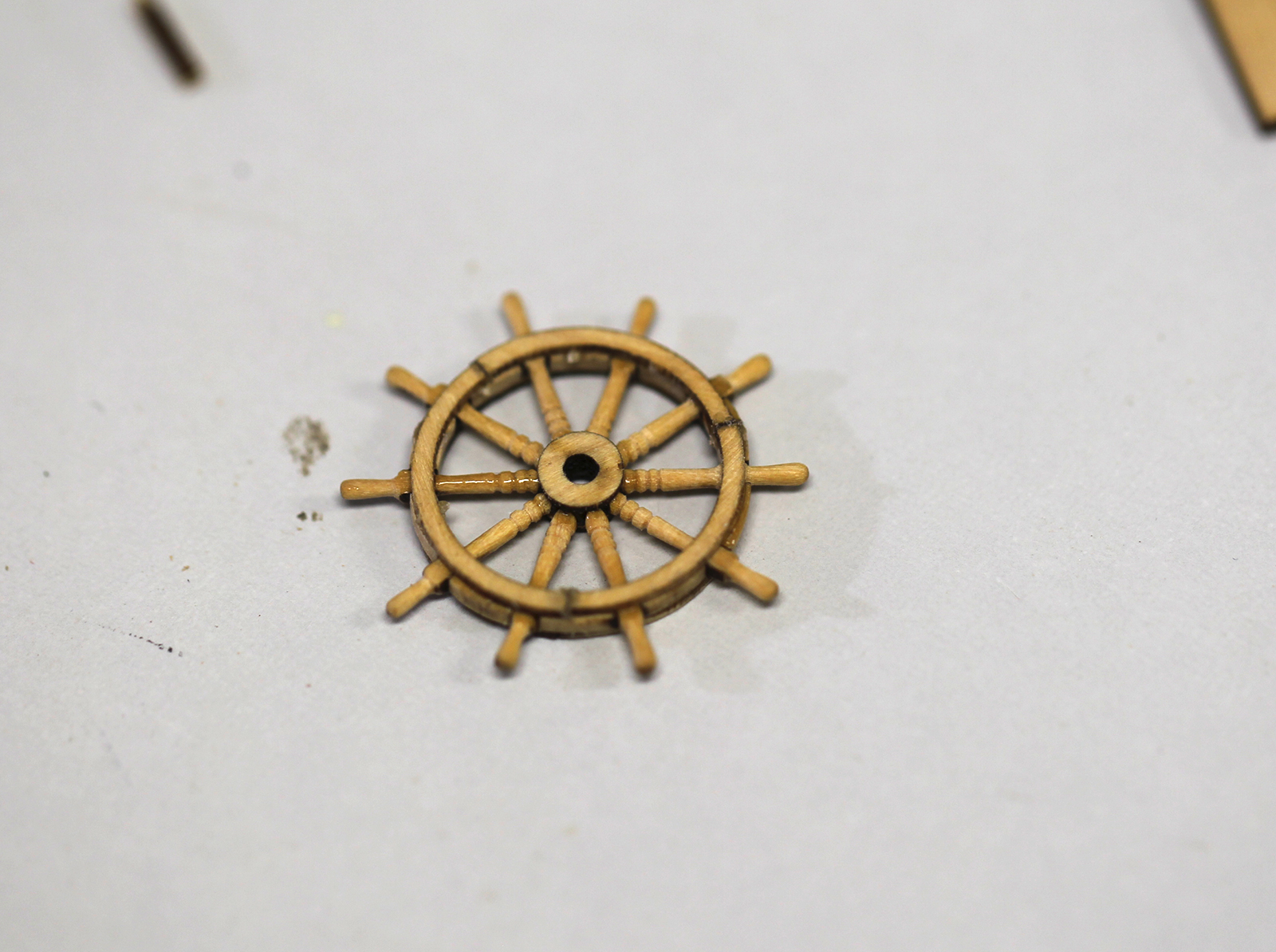
Finally, the entire wheel is sanded and smoothed with 600 – 4000 grit sandpaper, then stained. Because the char lines and creases created by each piece made visible lines in the wheel, I chose a darker mahogany stain to cover that up as much as possible and make it less visible to the naked eye.

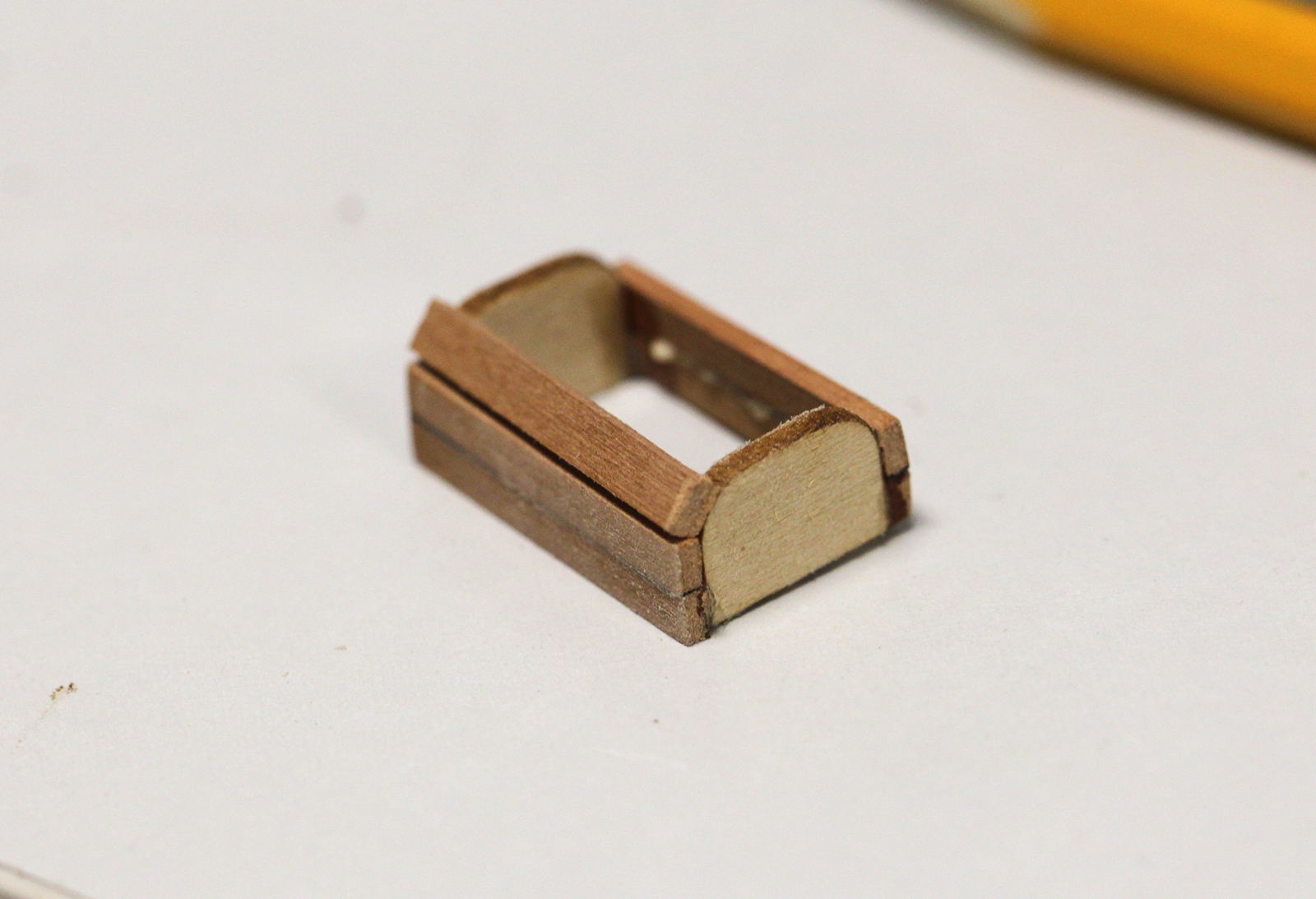
Because the wheels were now more ornate, I decided to give the base for the wheels a different treatment as well. Using a scrap of wood left over from a penholder I acquired some time ago, I cut and sanded down two pieces of framing to whole the new wheels.

I’m not entire sure what kind of wood this is, but it’s very dense and very hard, so although tedious it made for precision carving and sanding, and ultimately I believe looked pretty good.

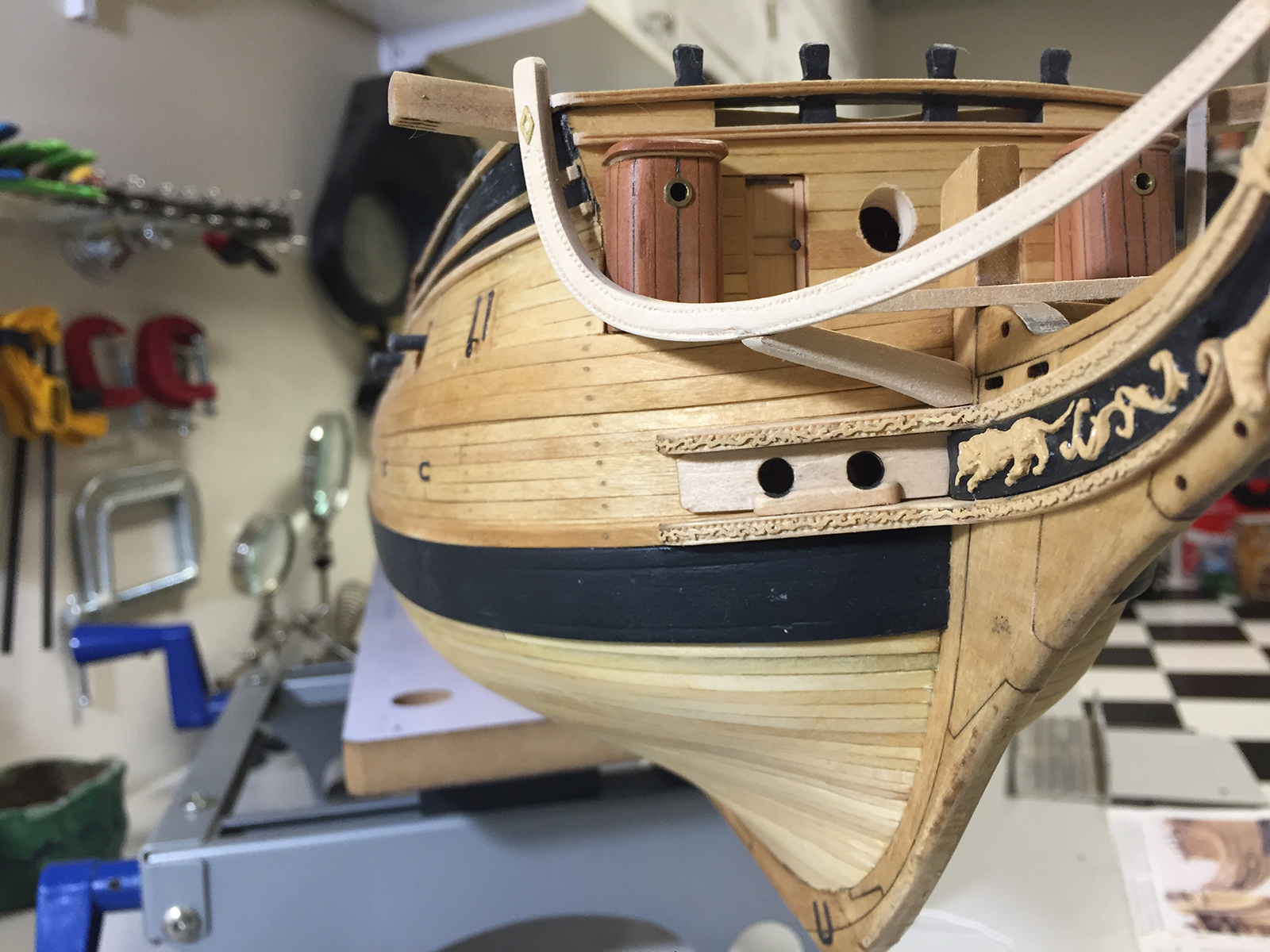
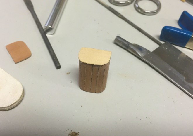
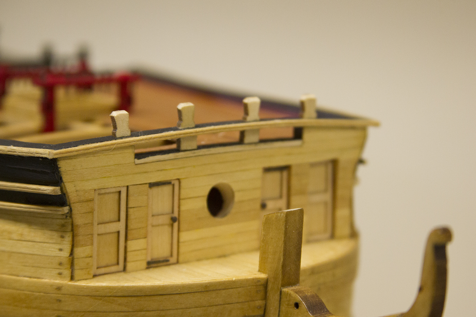
The ship’s roundhouses were at the fore of the ship on the bow. The Confederacy’s Roundhouses seemed to be pretty straightforward, however Augie had written in his notes that he was intending to use the Swiss Pear instead of the lightwood indicated in the plans. I really liked this idea, as it would surely set off a bit of color on the bow of the ship. It really didn’t change how I approached the Roundhouses initially, but soon after I discovered the slightly thicker Swiss Pear was going to involve a little more intricate bit of beveling than the stock parts.

In addition to mitering the edge, I also sanded the inside of the strips with a round file to try and match the shape of the guides. Then I marked the inside seams with a sharpie to simulate the caulking between the planks.

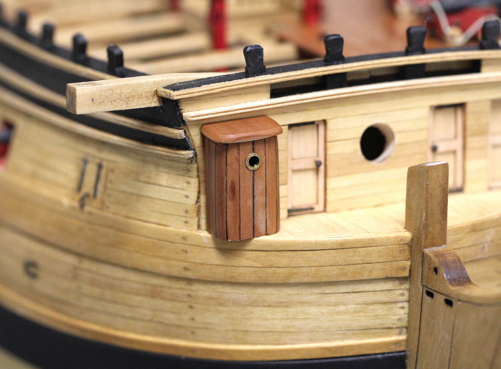
Chuck’s original plans & instructions call for a bit of 28 gauge wire glued under the overhang, which is a very nice touch to give it a sense of crown molding and insulation. Instead – for me to pull in a little bit of the natural color of the bow, I used the original light colored overhang, sanded it down, then covered it with the swiss pear roof.
Finally, I dug up in my “extra pieces” bin, some small circular brass rings with a lip that came from who know’s where, and I used those to bring out some detail int he ventilation scuttle.

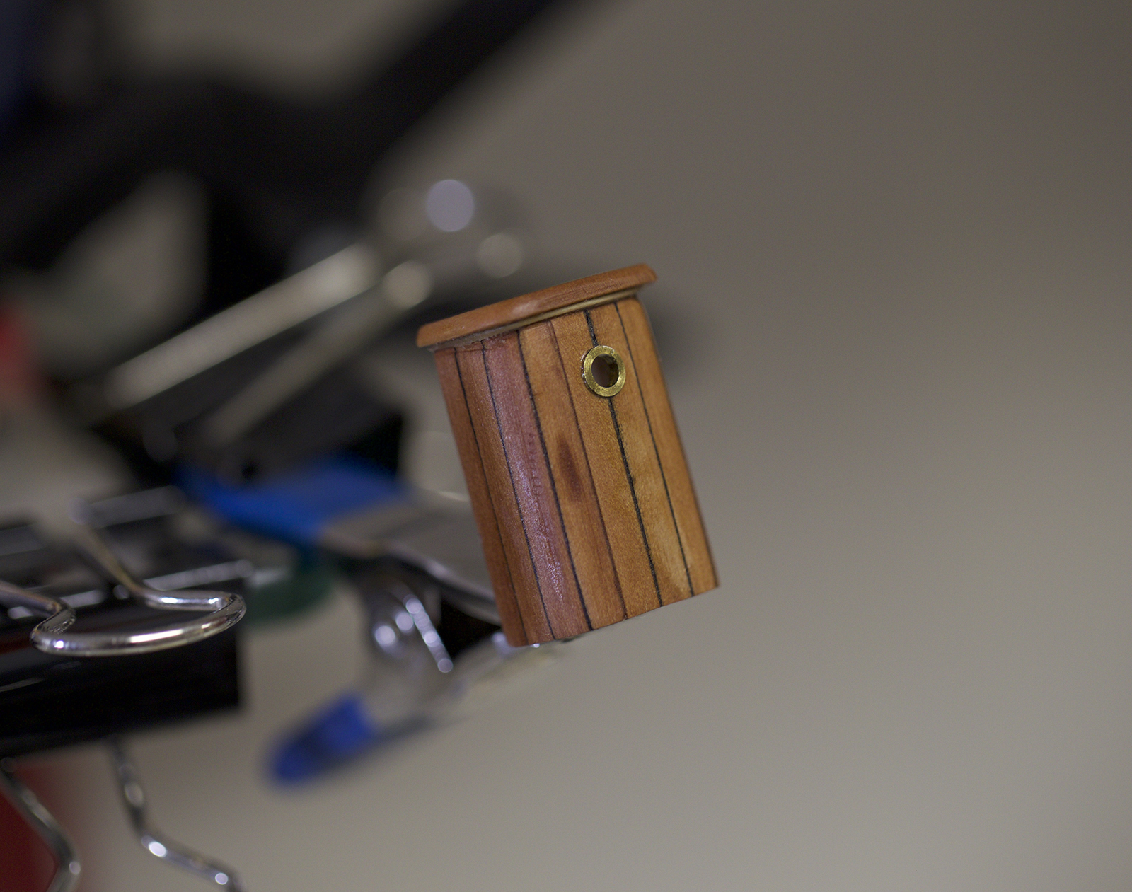
Ultimately, Augie nailed it with his approach (as he always did), and I really love the way the swiss pear looks on the bow.
Progress has been difficult in 2016. As my business travel seasons kicks into full gear, the progress on the ship happens in spits and spurts. But I remain persistent.
I started with an easy updates that included blacked brass posts and rope rails. The rails were either rope, or metal; in this case Augie had already opted for rope on the lower decks, so that’s what I continued with on the main & upper decks.
Next up is the bow of the ship, and firstly the catheads. Although this was a pretty macro process if you will, the catheads needed to be fitted perfectly snug, and it involved cutting out a portion of the bulwarks – which is always a bit nerve-wracking.
First, the catheads themselves are cut out of the laser-cut molds, and shaped. A bit of the bottom has to be wedged off to match the slope of the deck.
Next comes the delicate process of cutting out and fitting the catheads into position. The trick here is to cut out the rail smaller than necessary, then slowly file out and sand the slits until the catheads fit as snug as possible.
There was a lot of delicate sanding a tiny bit at a time with varying sandpapers and files, then fit the cathead, then sand some more. A patient process to be sure.
T he bottom of the cathead doesn’t quite fit the edge where the deck meets the side of the ship. So, a smaller wedge is cut and glued to match the edge of the deck where the planking and the bulwarks meet.
The slots for the sheaves (small pulleys) were already cut out from the catheads, which made things much easier. However, I wanted to accurately represent the sheaves themselves. First, I sanded down a strip of boxwood as thin as I could without compromising the integrity of the wood.
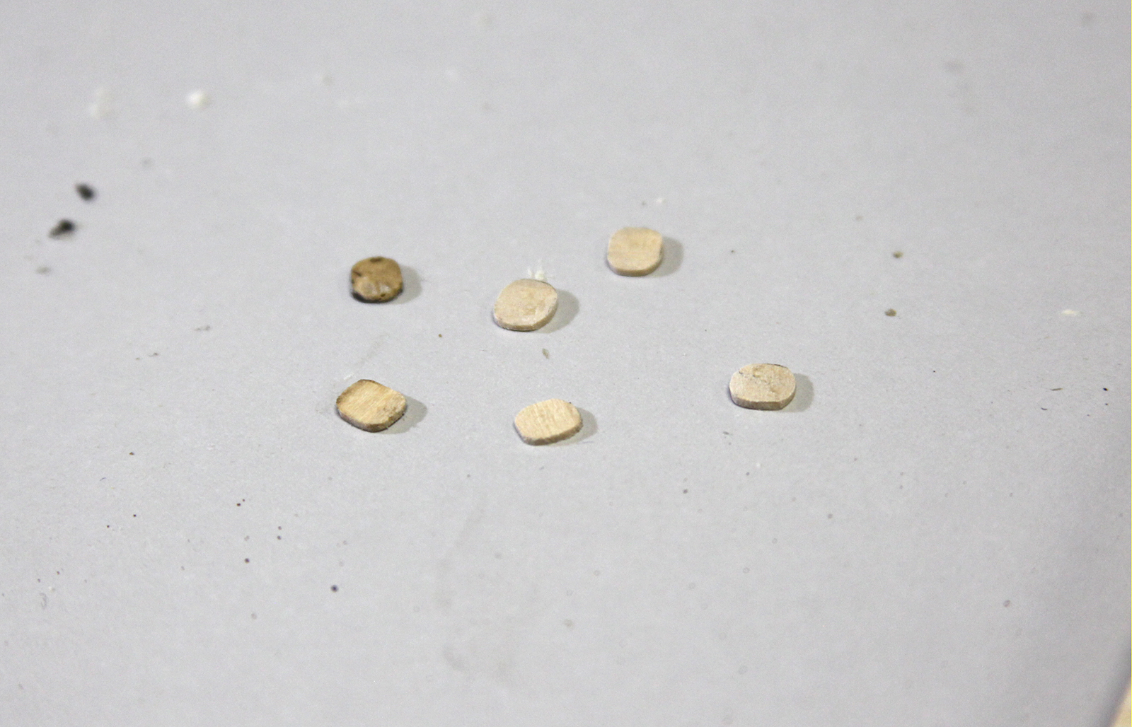
Although the original sheaves would have obviously been round, that didn’t look quite right. So my simulated sheaves ended up being sort of a squared off oval. This gave the final look a more accurate feel.
Finally, the catheads themselves were carefully glued into place and clamped until they dried. Since the port and starboard sides of the ship were not exactly symmetrical, it took some sanding and fitting to get the catheads to look as even as possible.
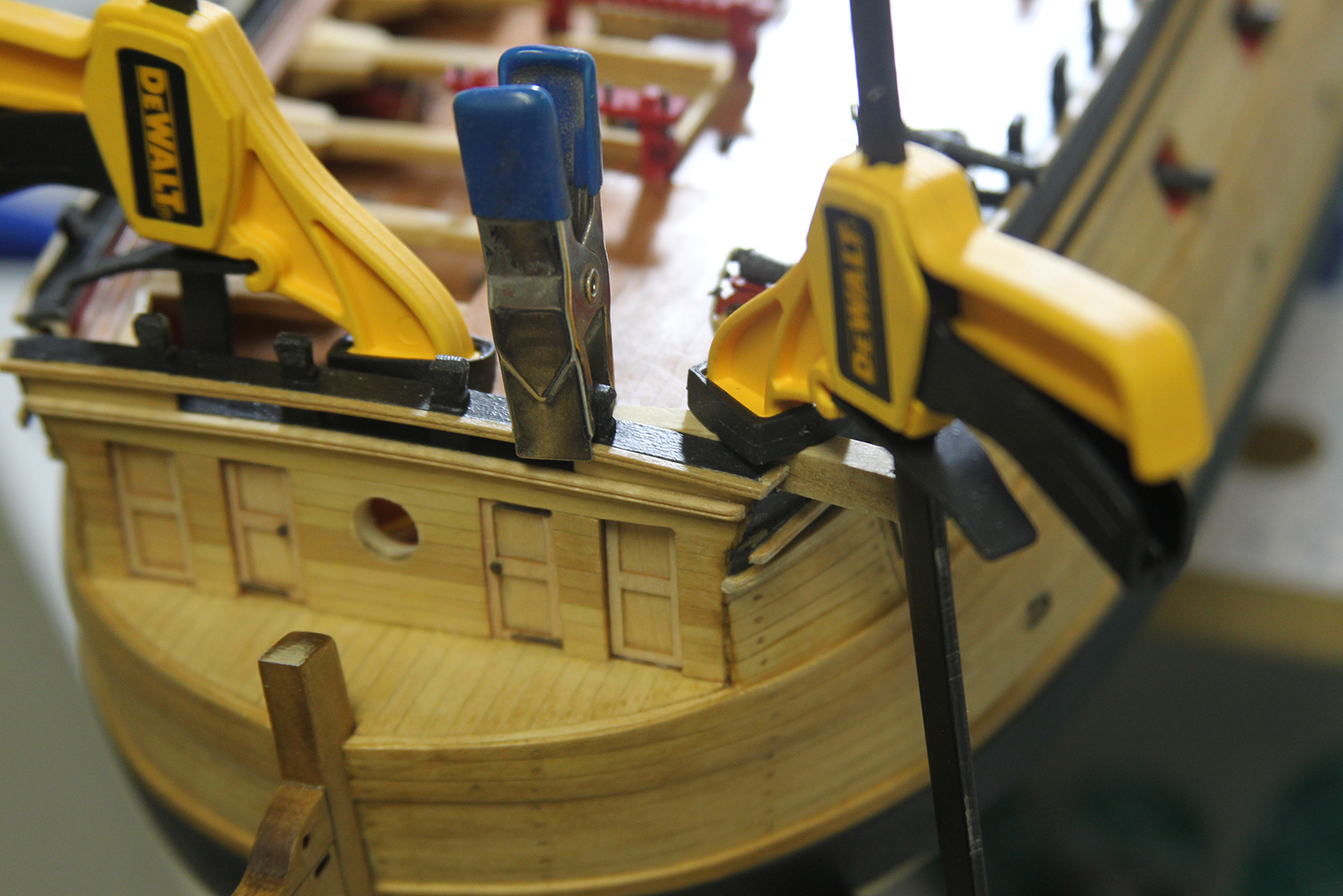
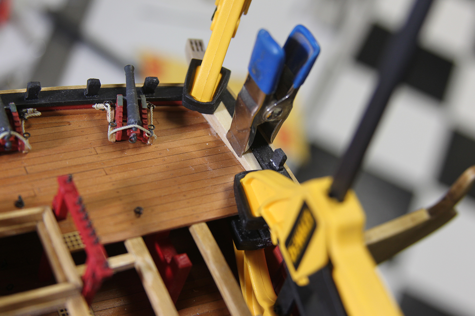
Finally, everything is gently sanded and evened out as much as possible. Then, the catheads are coated with a wood conditioner, natural wood stain, then finally a satin lacquer.
Continuing my repair process, and cleaning up some of the ship, I got a good bit of work done on the Transom. It took a couple bumps and bruises along the way, and some of the paint had shipped off the figures, and created some blemishes on the black. Also – I wanted to touch up the window frames a bit. Augie did such an awesome job with the window “glass” that I wanted to even out the finish and color of the frames to match the rest of the smooth look and feel of what he had going.
The BAD new is – I jacked up the cove in the process (Sorry Augie!) so I had to rebuilt / reshape it. WHAT A BEAST. This gained me an entirely new appreciation for Chuck’s laser cut parts! *laff*

After much soaking, shaping, breaking, re-soaking and re-shaping, I finally got the cove repaired and replaced and stained to match.


The GOOD news is – this marked a small milestone in which I could fully press on with new progress and moving forward with the build.
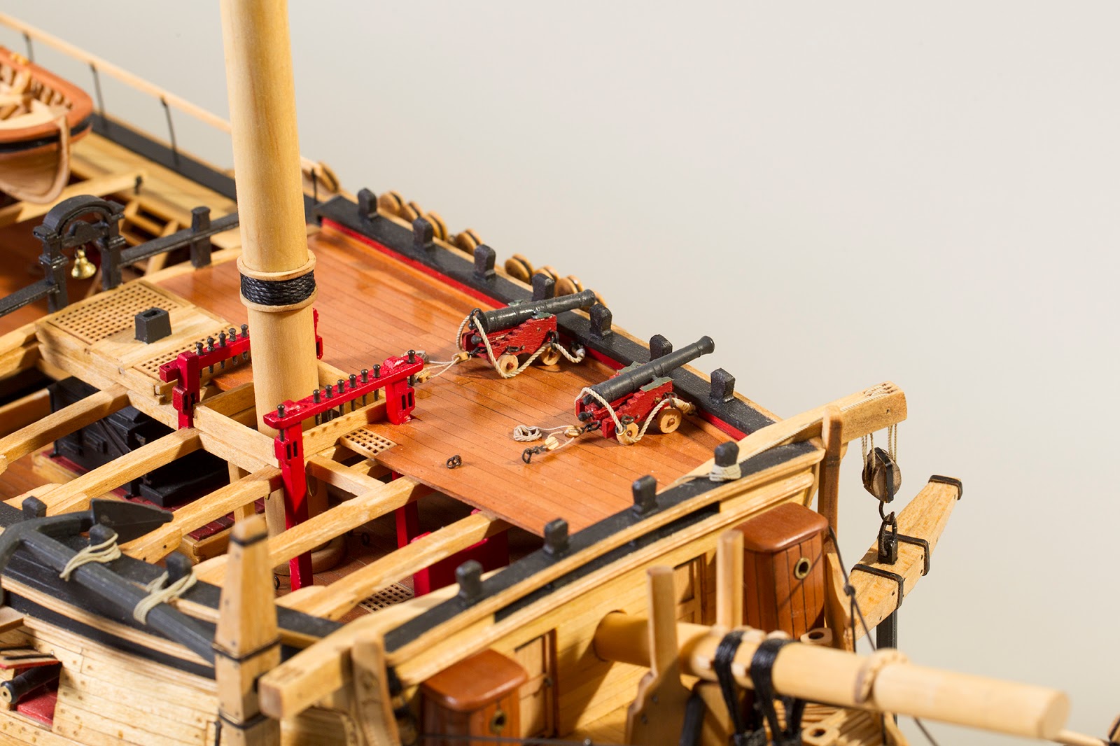
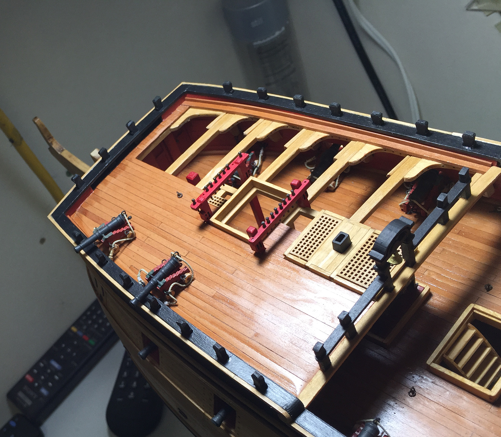
Although the plans for the Admiralty version of the Confederacy are pretty clear in terms of using limited munitions and other bits as an example of what was supplied on the ship – I’m a pretty bit fan of fully loaded vessels, and little details to add realism.
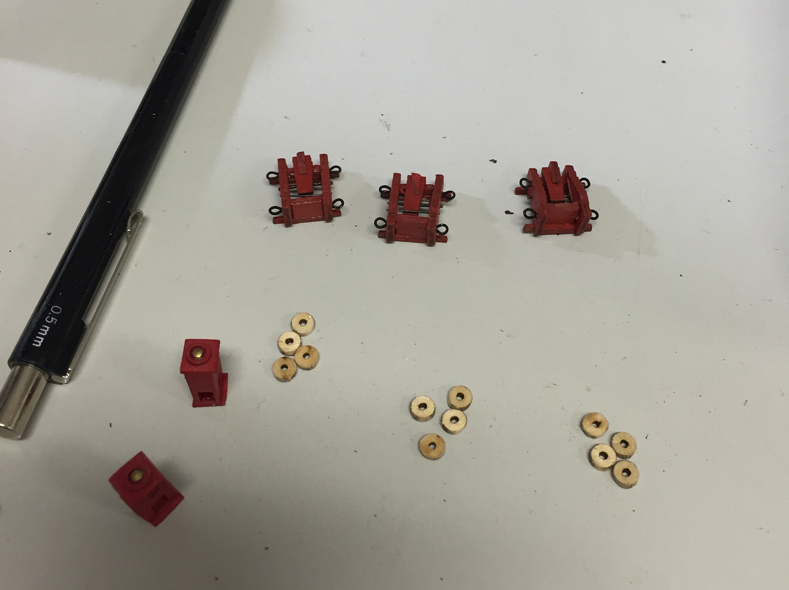
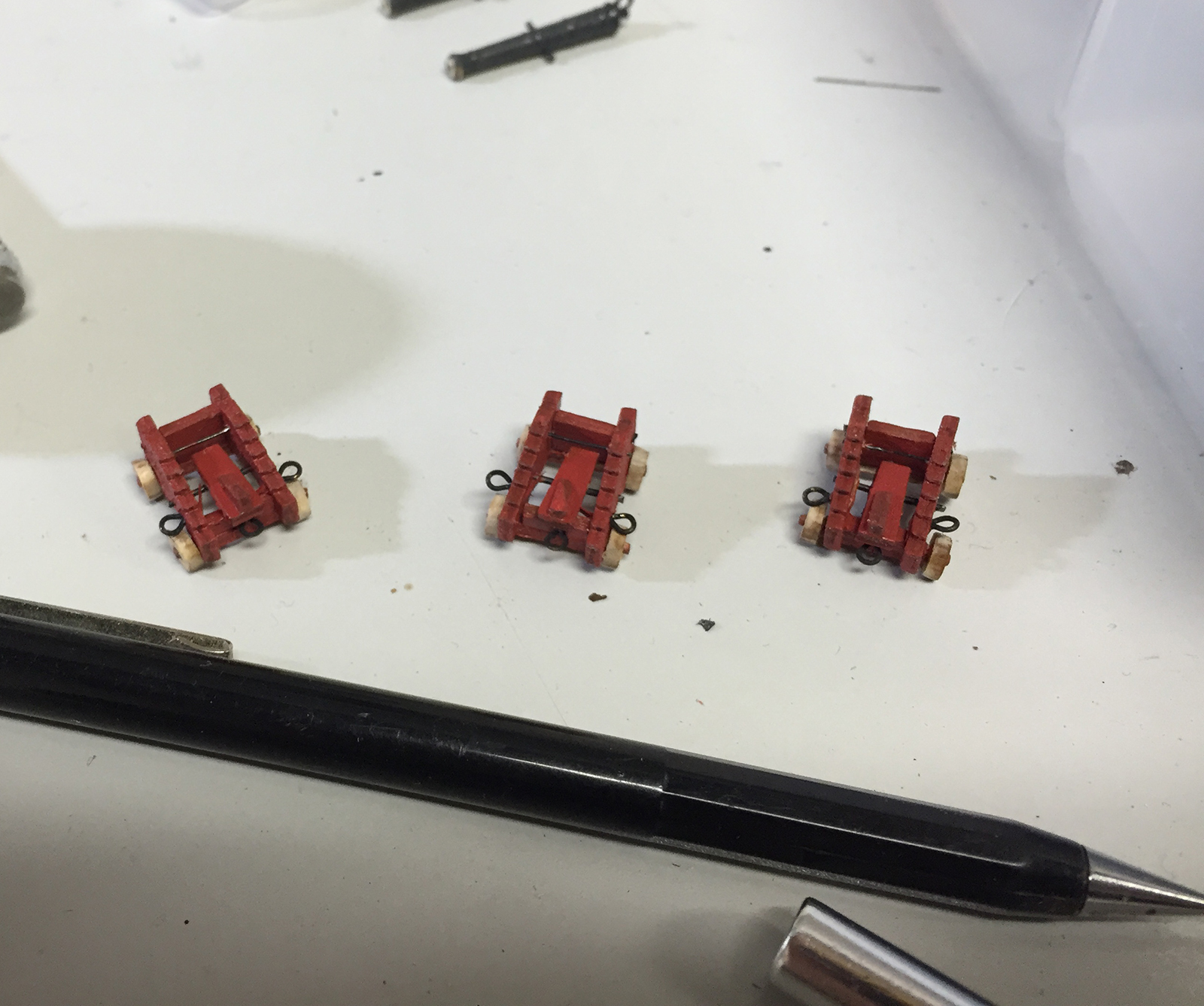
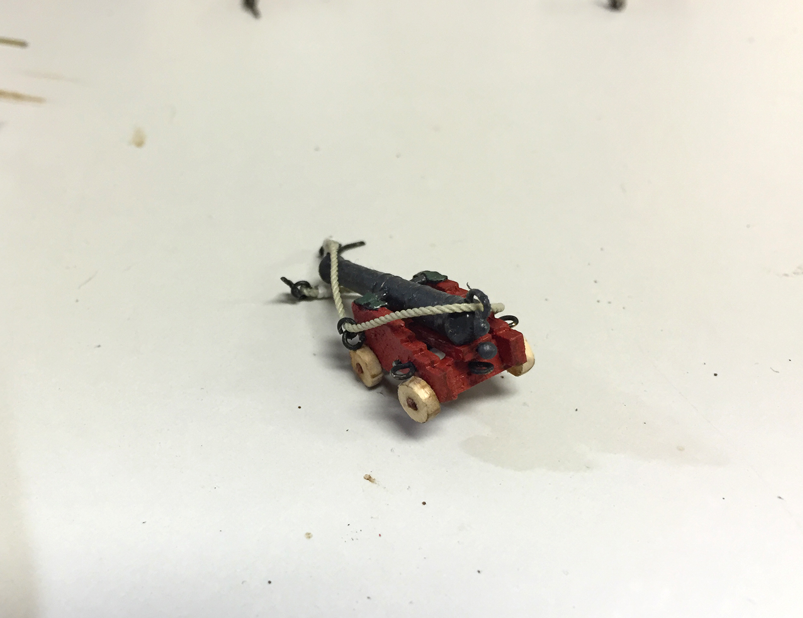
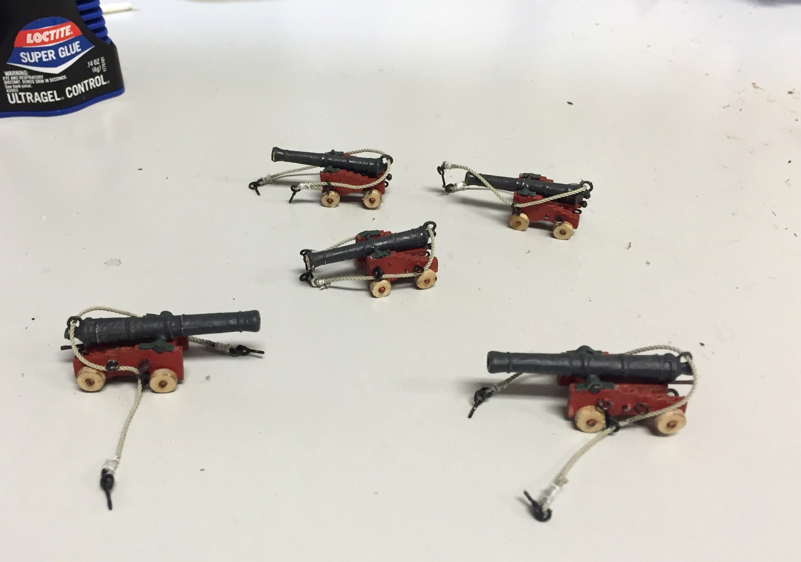
So I decided to add a few more of the ships cannons. To that end – even though the plans call for just four six pounders, I wanted to fill out the upper deck a bit more – so I ordered a few more brass cannon from Chuck and set to work added some guns and putting together some carriages. Of course I referenced Augie’s hard work so I could replicate as closely as possible. Obviously I didn’t want the additional guns to look any different from what he had on deck already.
Although the paint was given to me with the kit and instructions, it was a little tricky matching what overcoats, etc were used. But ultimately, I think I got everything pretty close.
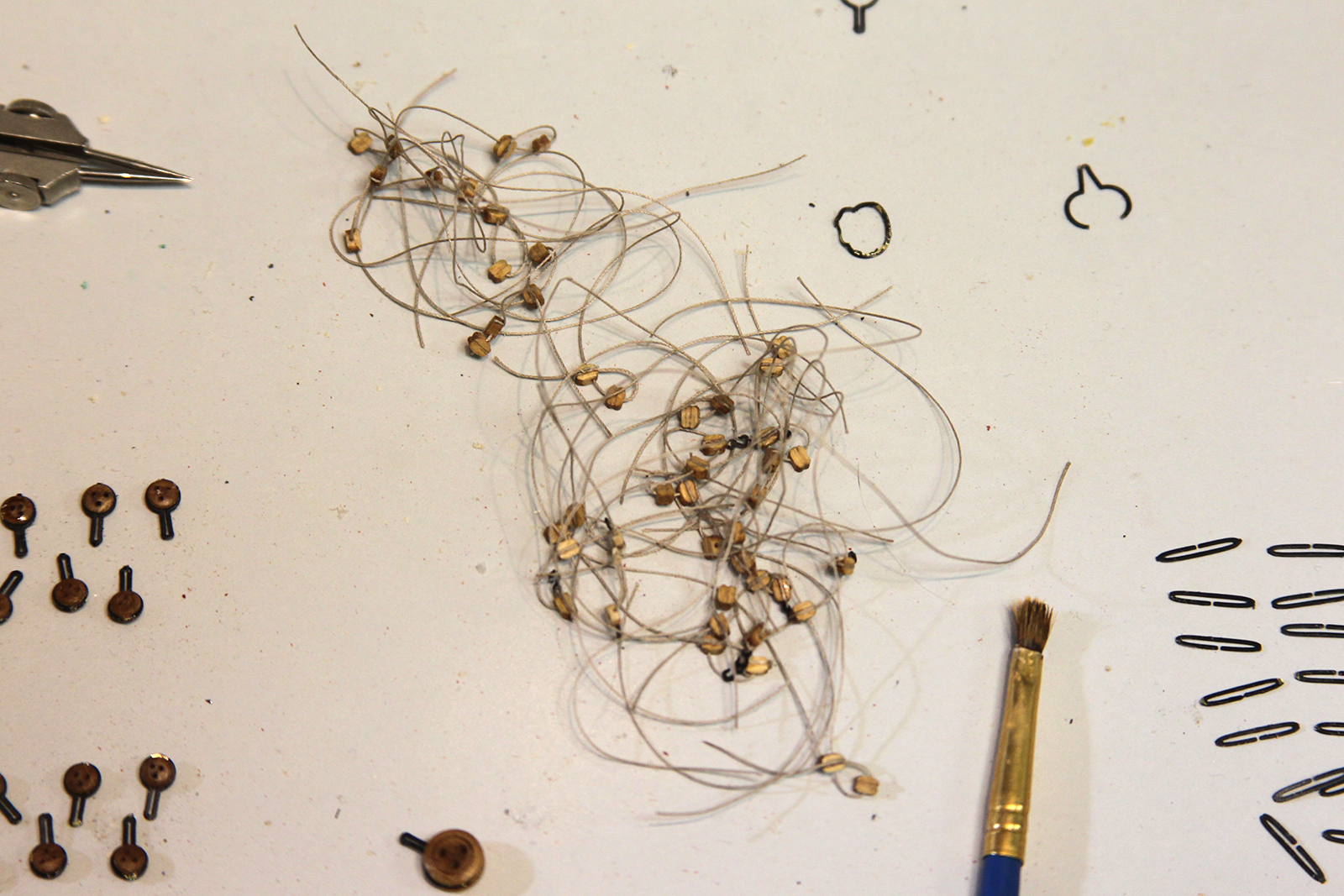
The small rings were bent each by hand with 28 gauge wire, then blackened and attached to the rigging and cannons. Each cannon was fitted with it’s own rigging ring. This part was a lot more difficult than I anticipated. Glue doesn’t hold well to brass, so i had to drill initial little holes to make the placement work.
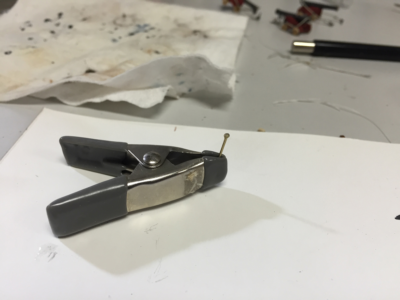
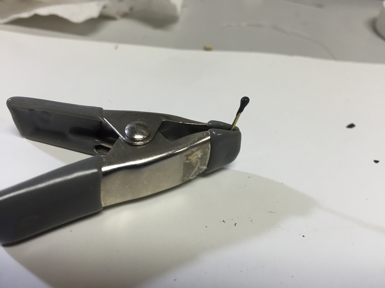
Now, one part that threw me, and I couldn’t find reference to in Augie’s log – was how he created the knob/handle on the stool bed. So I took a nail, added a glob of super glue, then painted it. I don’t think it’s noticeably different from Augie’s work, so I’m pleased with that.
Ultimately, I came up with the extra three six pounders, and the two 12 pounders matched almost perfectly.
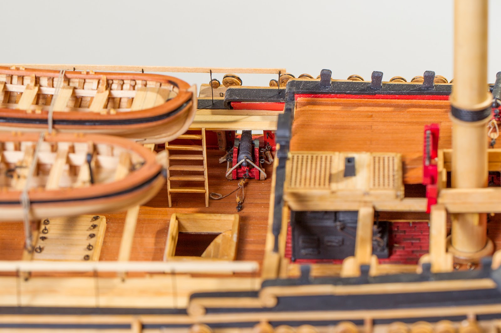
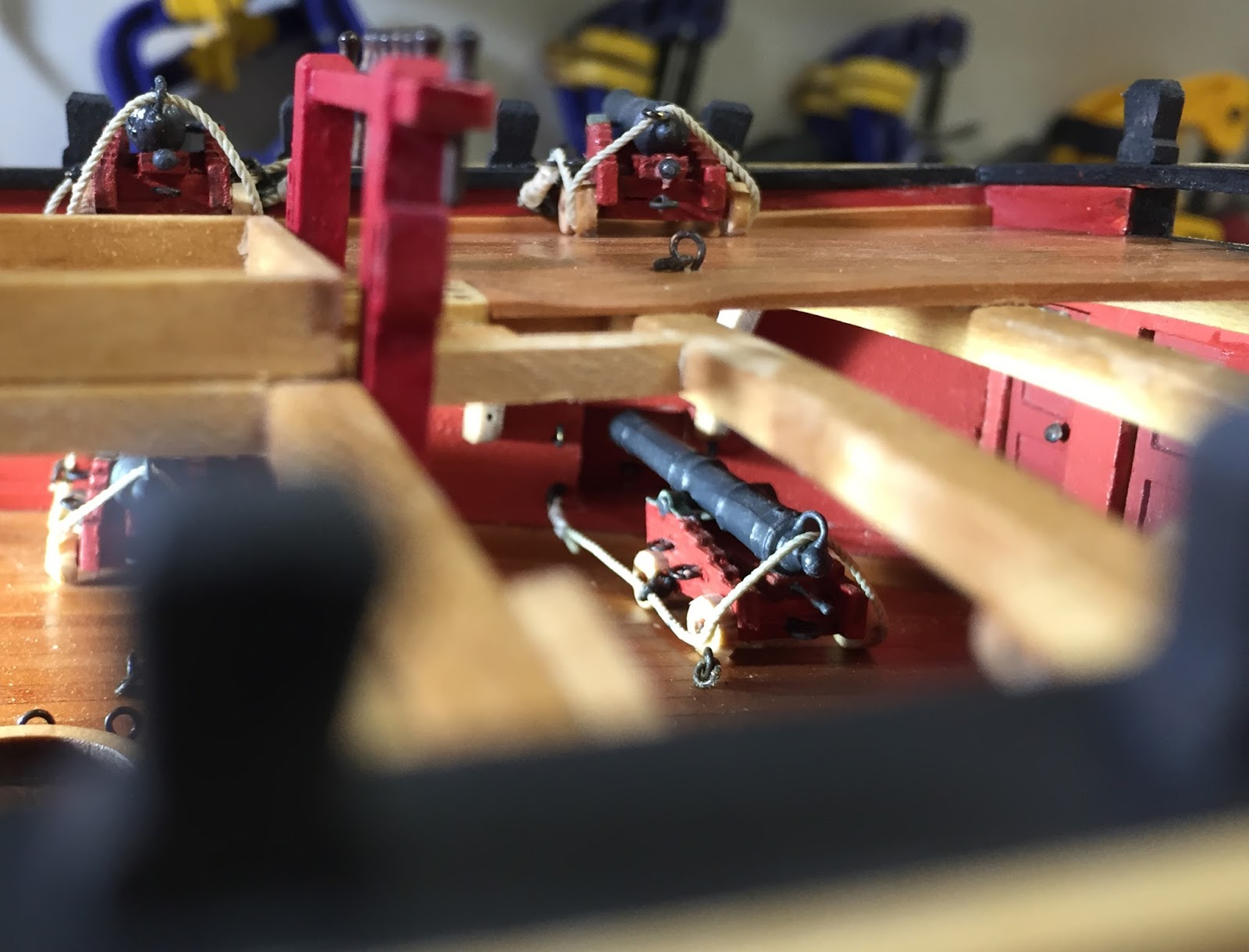
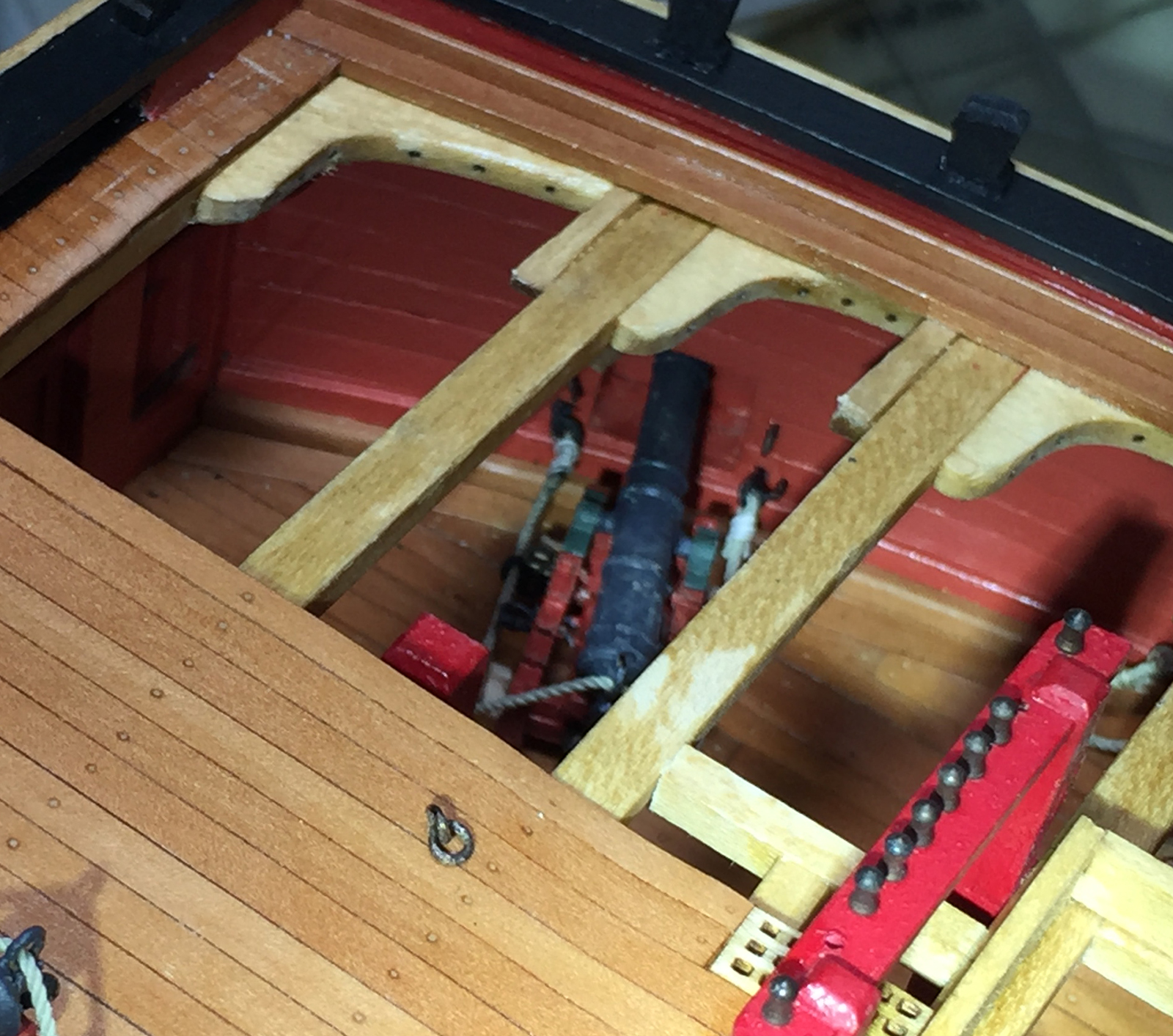
As it turns out – replicating the cannon was the easy part. The difficult part would be placing the cannon beneath the already built foredeck and aft. Obviously, the other cannon were placed earlier in the build, then the upper decks were planked over the top.
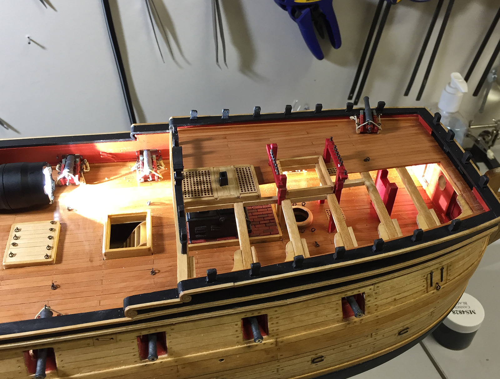
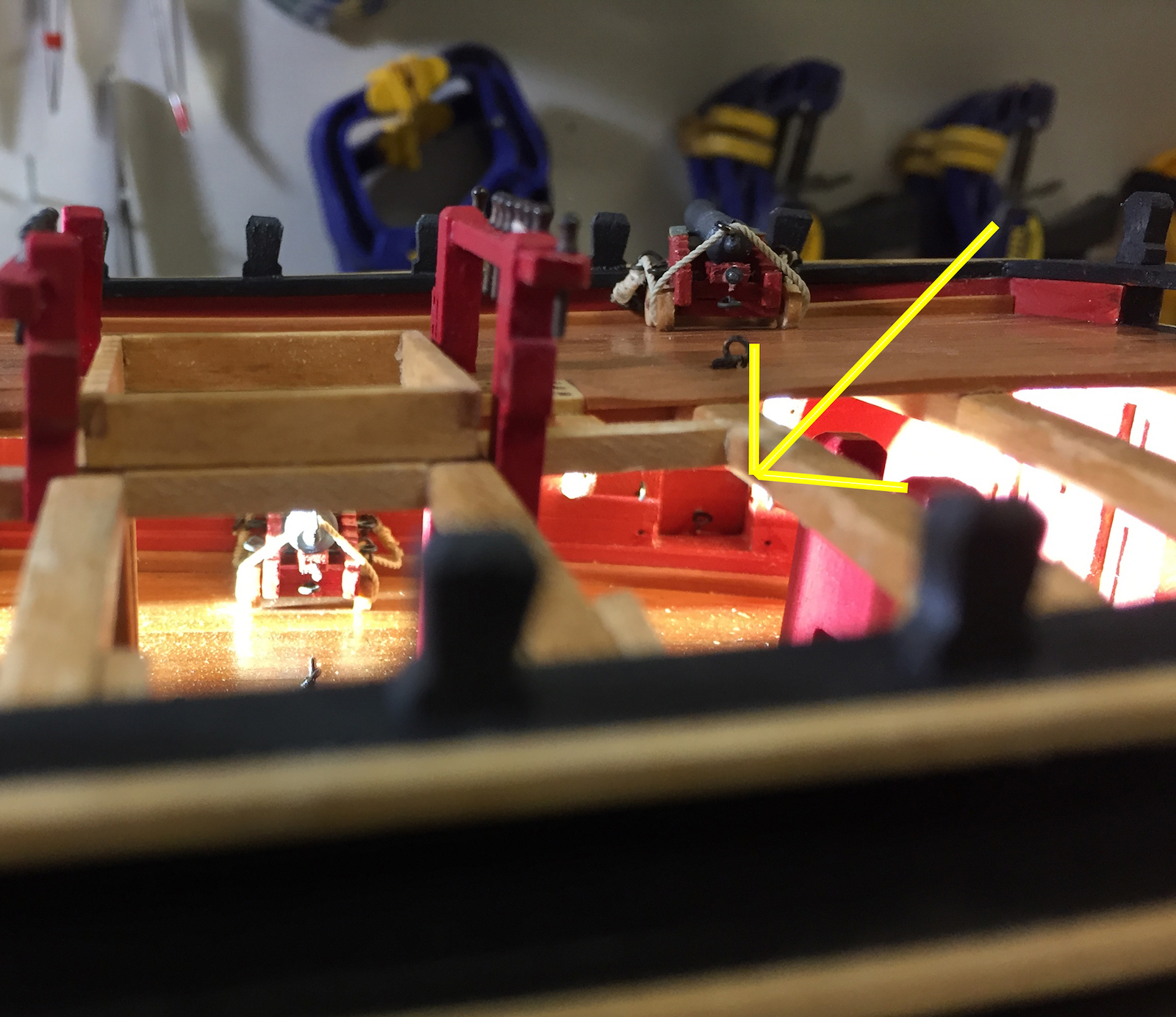
The yellow arrow indicated where the twelve pounders needed to go. A bit like a surgical procedure, I went back and forth between my long forceps and tweezers to get the cannon in place, then mount and glue the rings into the sides of the ship. Finally, the cannons were lifted up and a touch of glue under each rear wheel holds them in place.
I spent the weekend in the shipyard doing some initial repairs, then some new work. Because Augie hadn’t been able to work on the Confederacy for quite some time, it had collected a little bit of dust and had a small amount of disrepair, including some deck planks that had separated a bit and seemed uneven. So I cleared off some of the cannons and fittings, resurfaced the deck, filled in gaps with sawdust from sanded down Swiss Pear, then applied some tung oil and a light coat of satin poly. I also ended up touching up some of the black and red paint that had been negatively affected by dust, etc.


During the course of that – I noticed that the steering wheels that had come with the ship, well – just weren’t that awesome. After doing some searching for bits and pieces, it turns out it’s actually pretty difficult to find good wheels that are not metal and painted. So I set about creating new ones.
For Attempt #1, I cut off part of a dowel that was 15mm in diameter – the same diameter as the existing wheels. I mounted it onto my Dremel vertically, using a small screw attachment to create a version of a lathe. Then I used dental tools to notch and carve the piece giving it texture.


However, because the kind of wood I used was hard, but a little too porous and brittle, it crumbled when I attempted to cut it off the end of the dowel with it’s new shape. Drat.
For Attempt #2 I used a softer, but more dense piece of wood for the framing of the wheel. This wood is actually from an old pen case that I had from somewhere. You never know what you’re going to dig up in the extra supply bin.
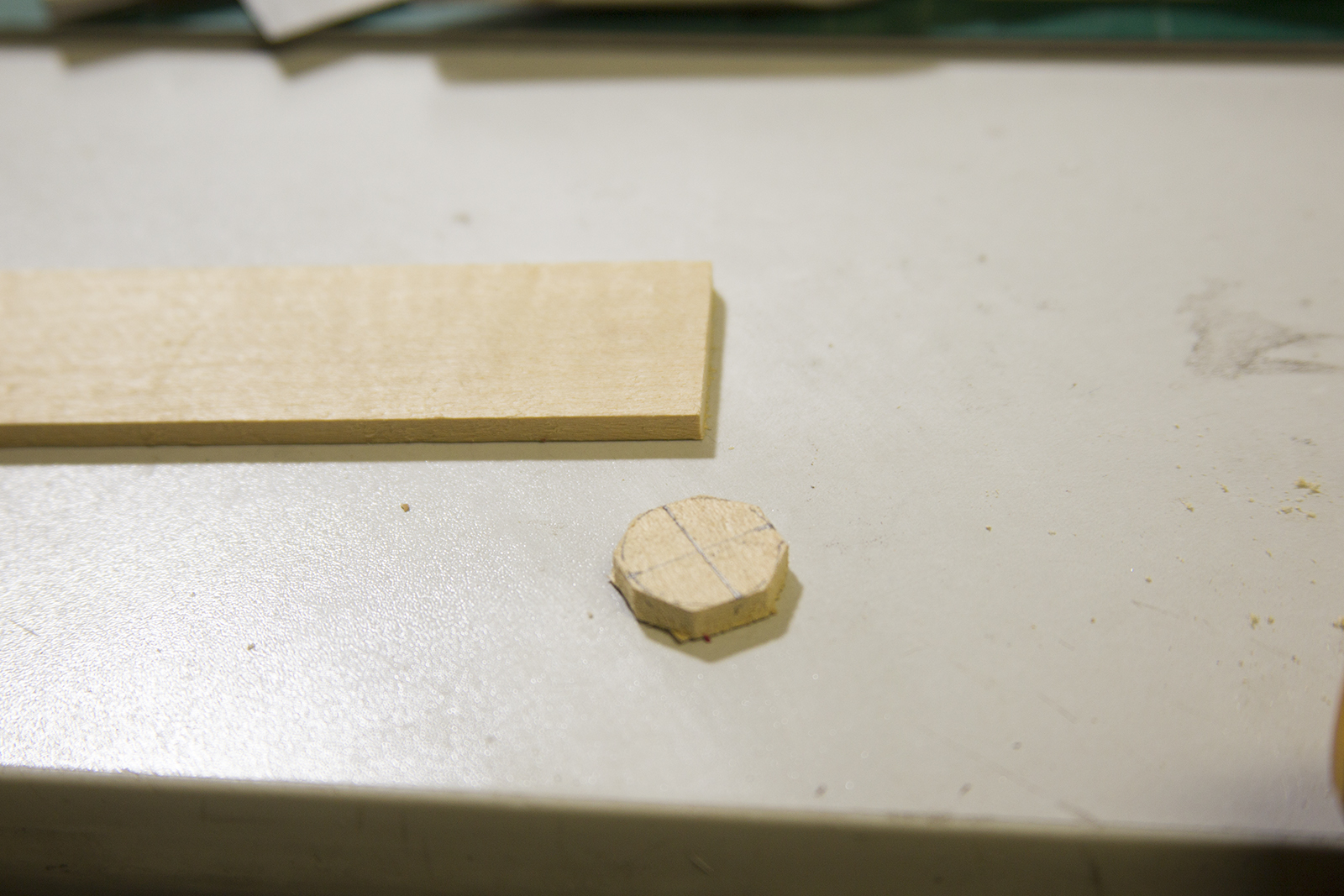
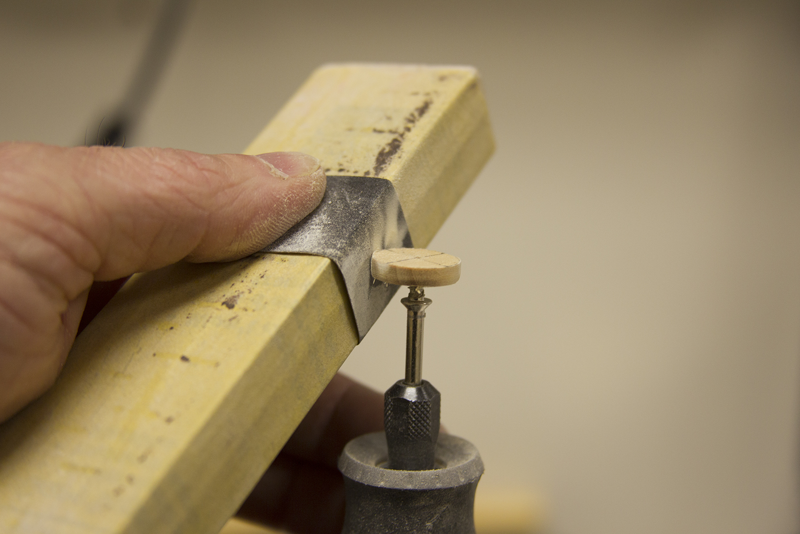


I cut it square, rounded the edges, then mounted it on the Dremel as before. I smoothed out the top and bottom and used my mini level to make sure it was even. I used miniature files to care out the edges and give the wheel some shape. For the spokes, I used a strip of boxwood, split it to 2mm, then rounded it with sand paper. Once again mounting it into my Dremel Lathe, I used a miniature file to shape the spokes.


I then mounted them around a center piece, and sanded my frame out to fit, notching the edges slightly to give room to the spokes. For the outer handles, I used the same process, and notched the frame out to fit the pieces.


Finally, I lightly sanded and added a cherry mini-wax stain. When it’s dry, I’ll sand it out with 1000 grit sand paper.


The Confederacy came to me about two thirds done. All of the framing and planking had been complete, and some of the deck fixtures and other pieces were also complete. Fortunately, there are clear notations regarding what had been left for later, and what was installed. Here are some pictures of her state on arrival to the Lehman Shipyard.
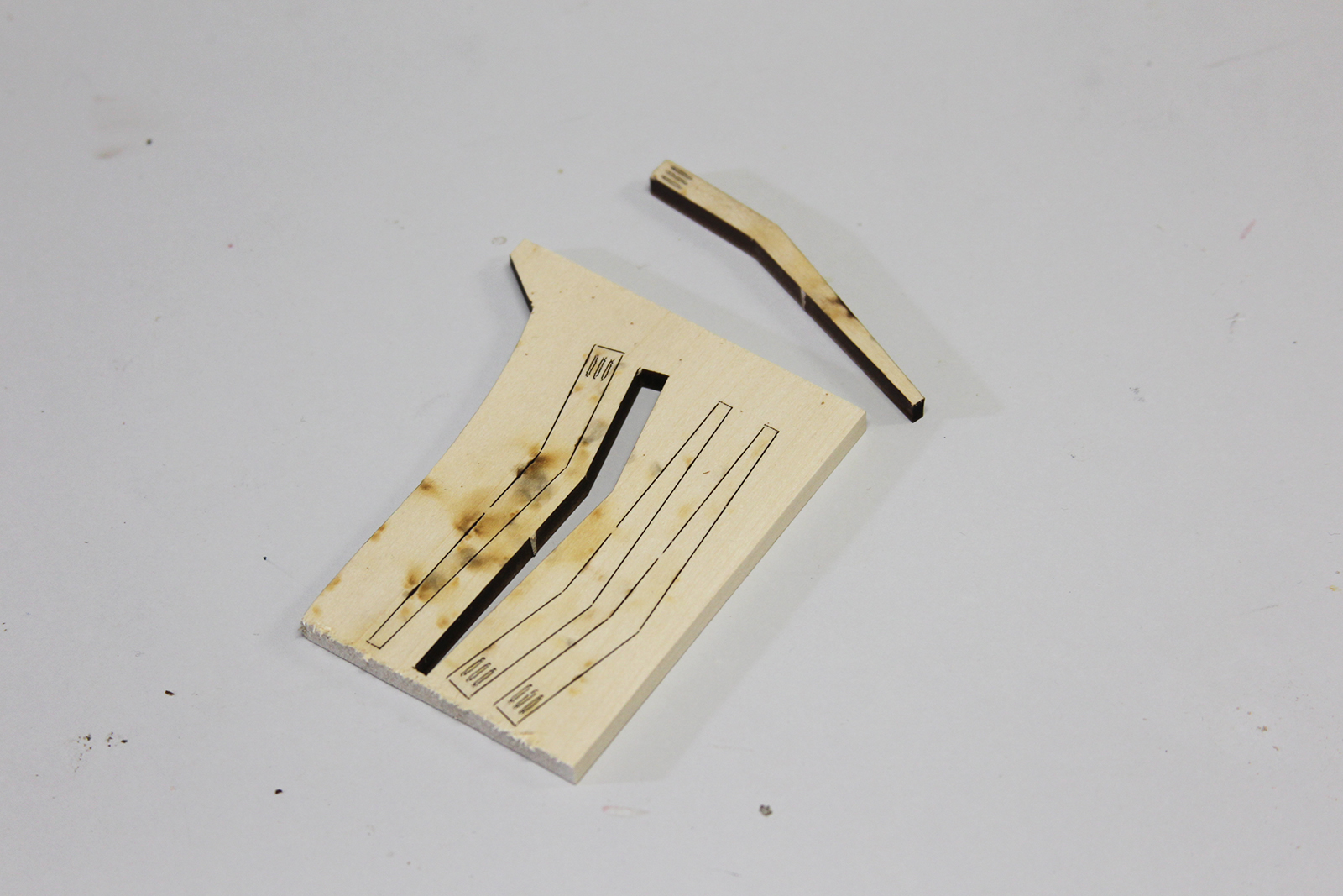
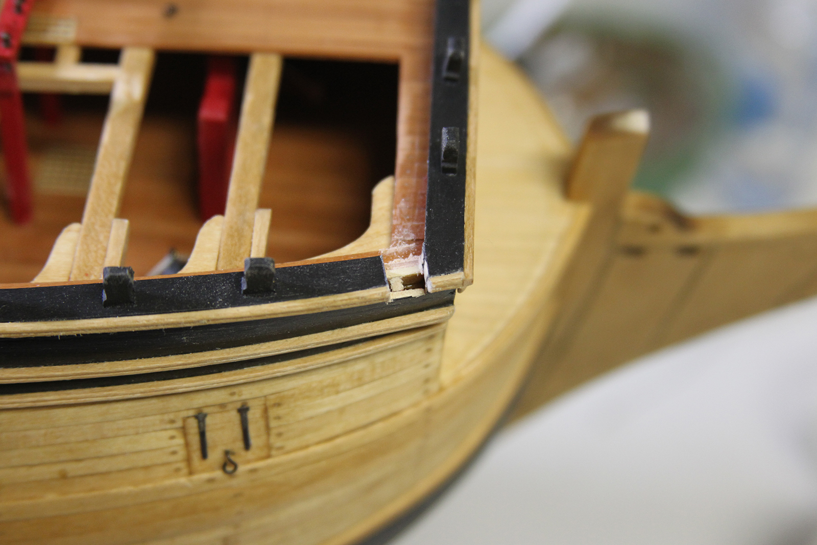
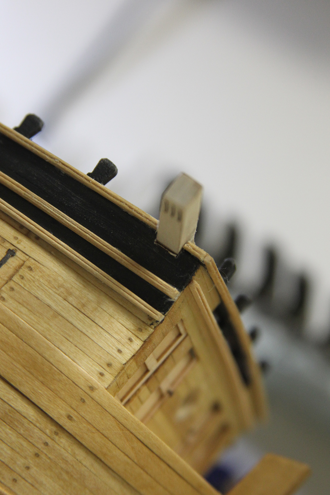
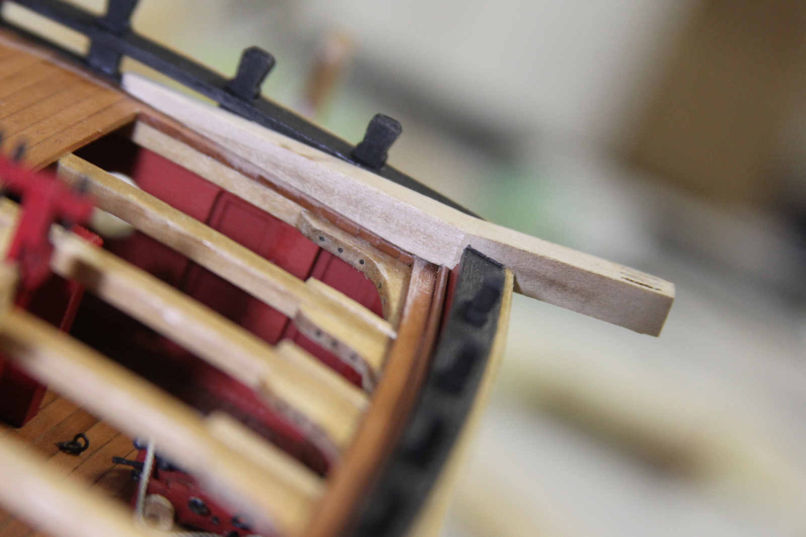
So, picking up where the plans left off, I started with installing the timberheads that go on the bow of the ship along the cat rail. Each timerheard is a laser cut piece that I removed, then beveled along the top on all four edges with a miniature file.
They’re mounted on the front rail first, with small, same-size posts between the rail and the bow of the ship. The rest of the timberheads are evenly spaced along the rail, then all are planted black. It took a little bit to match the blacks with what was used previously, but it all came out close enough to be unnoticeable.
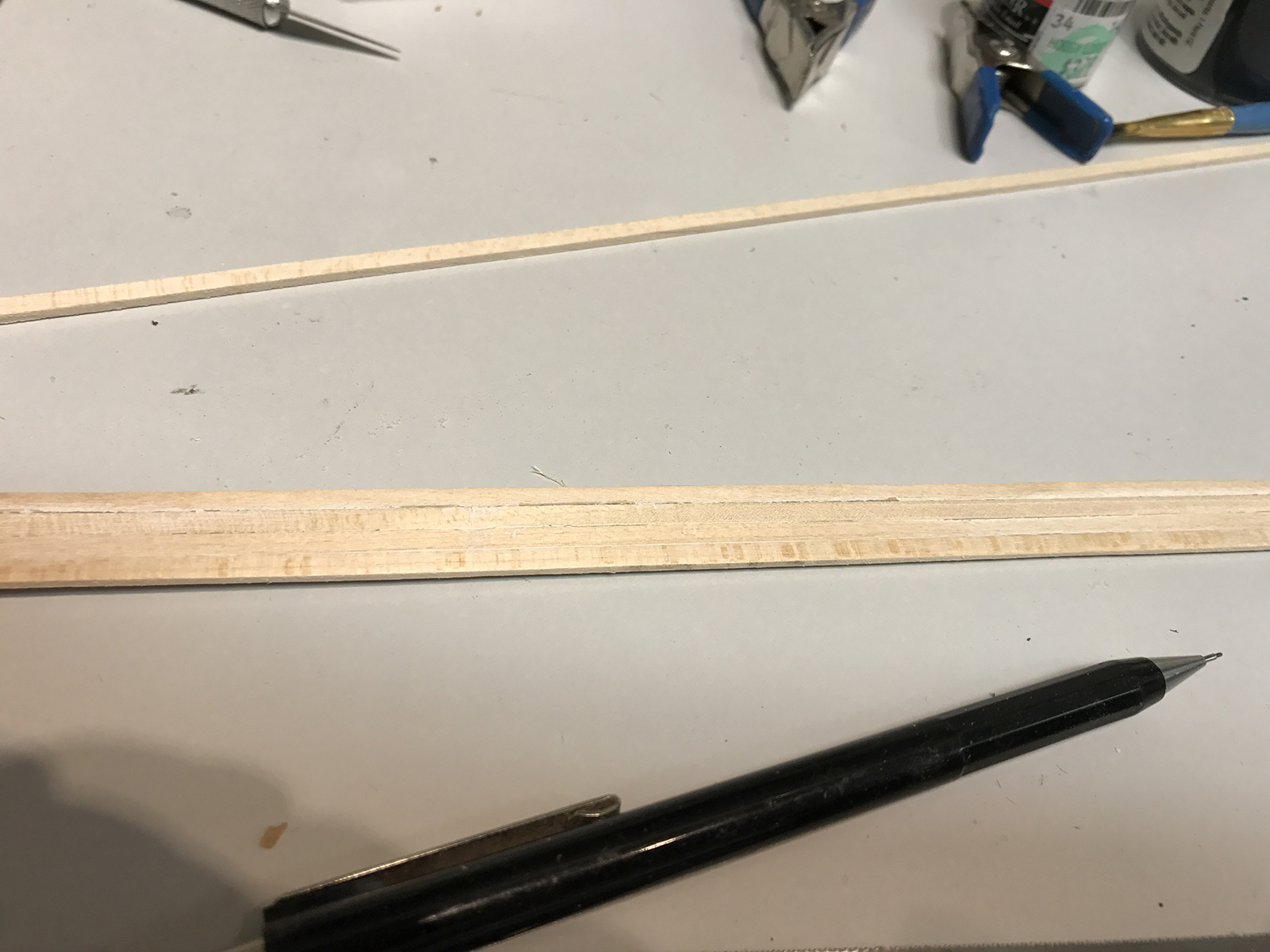
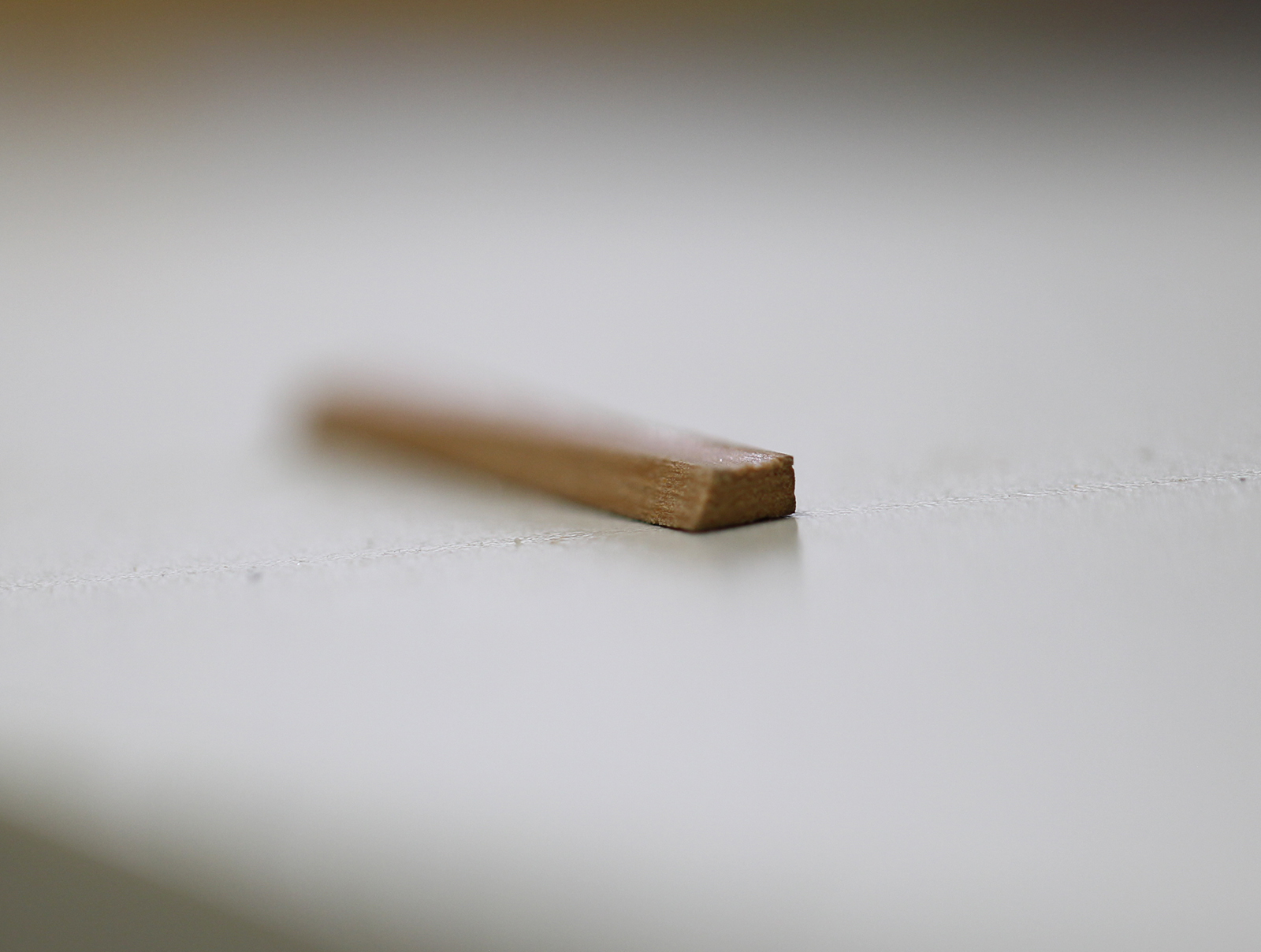
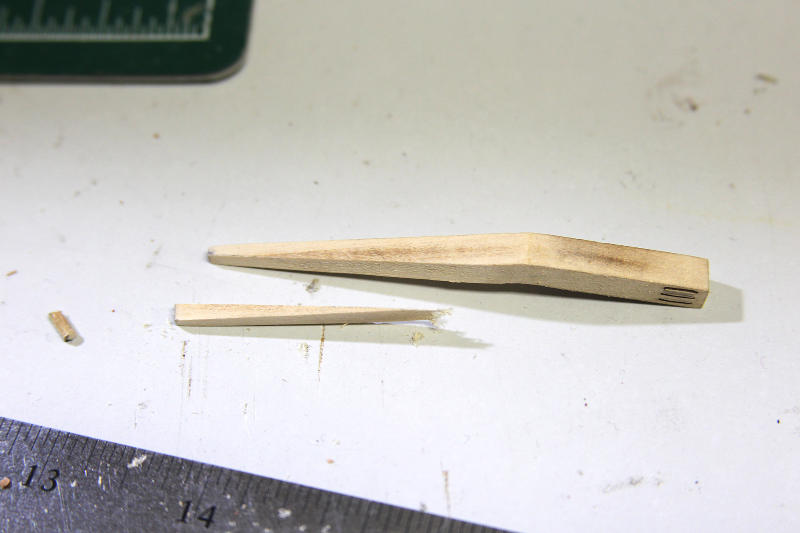
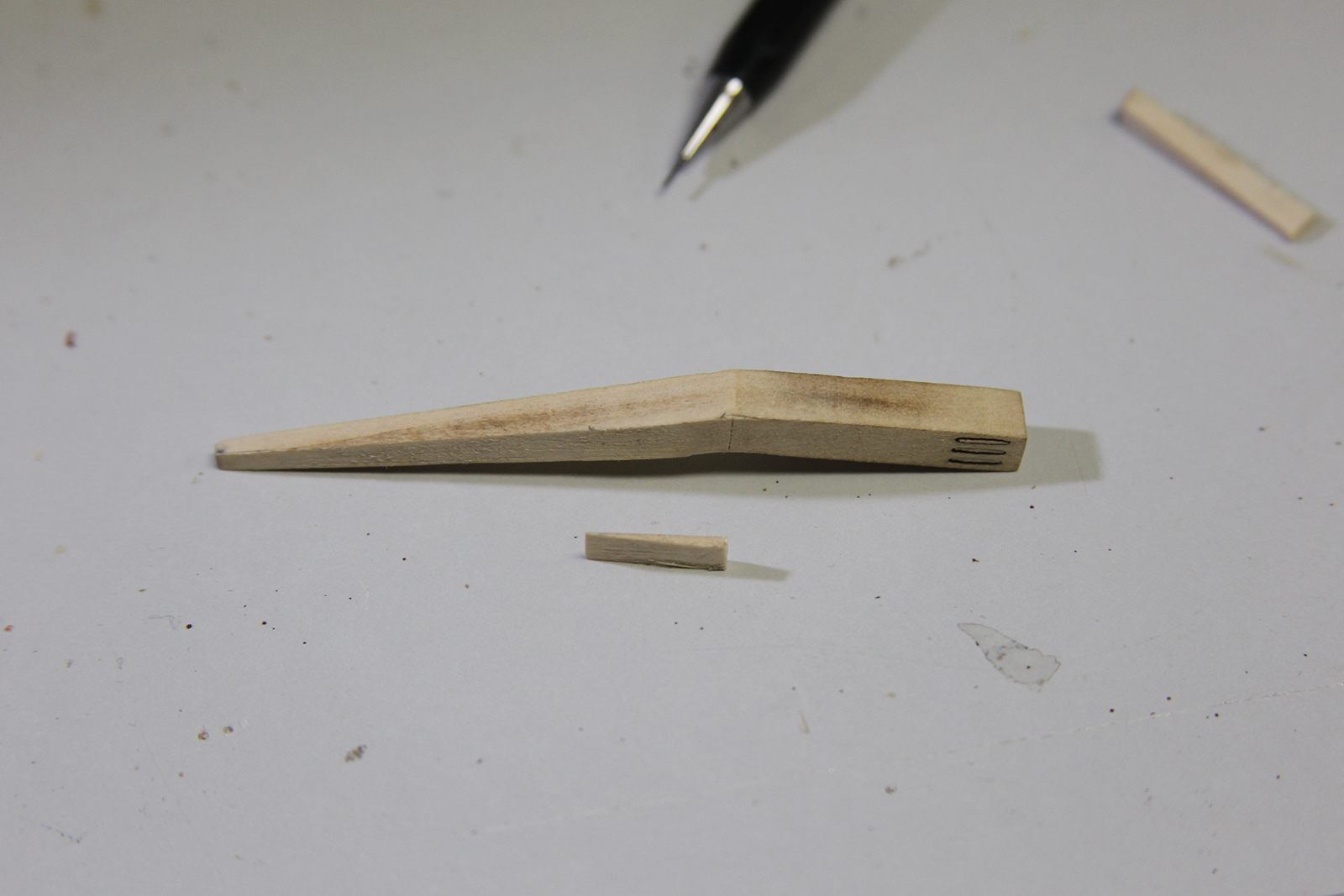
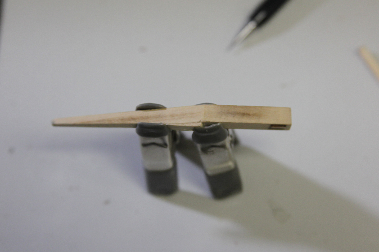
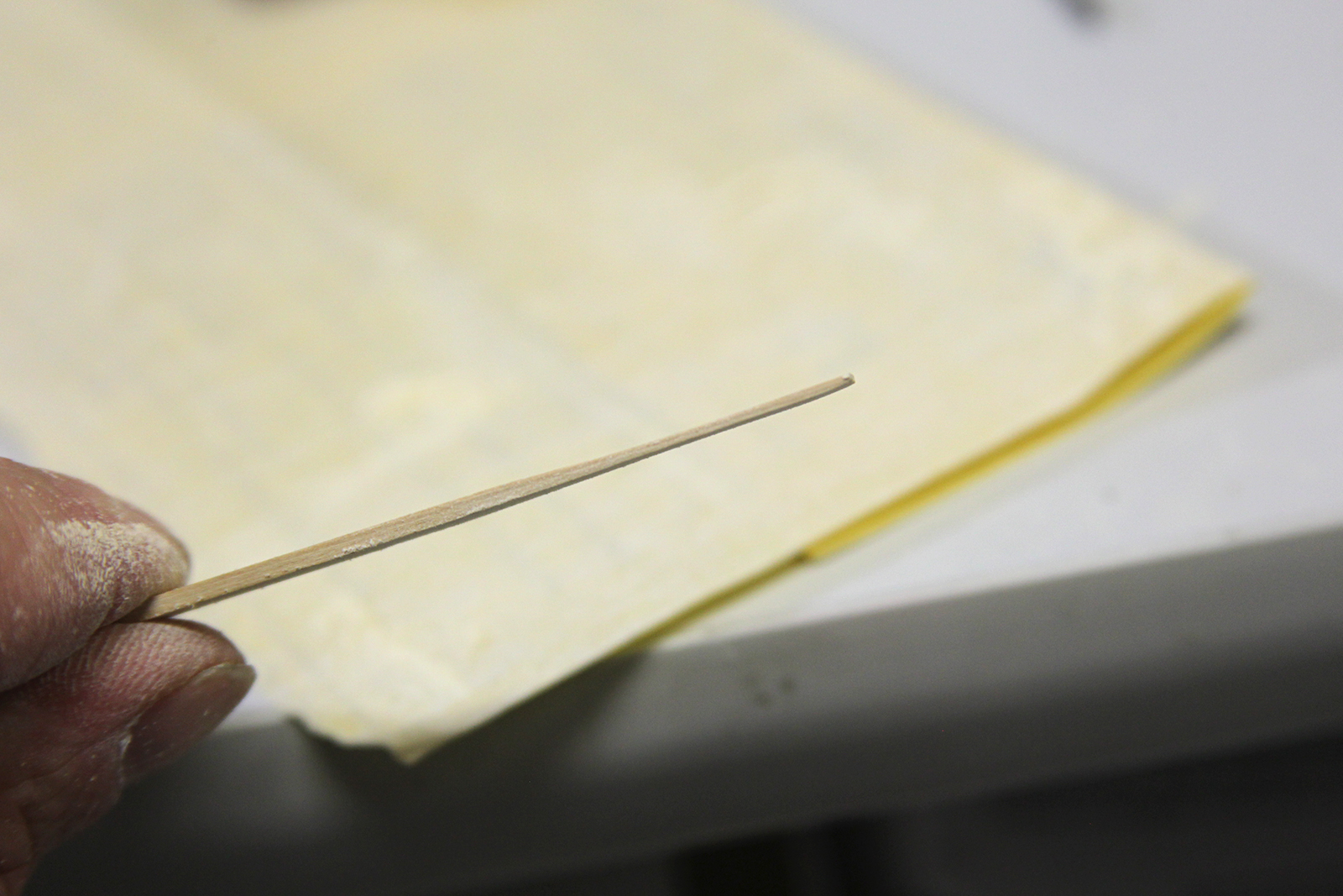
After completing the timber heads, I noticed a piece of molding was missing from the front. I wasn’t sure if it had fallen off or hadn’t been installed yet. At any rate, it needed to be done.
I matched the wood, then scored it using a metal ruler and an X-acto knife. After a couple of attempts, this gave me a straight light down the center of the wood that I could use as a guide. I then dug out a bit more of the wood and scored it deeper using my sharp end tweezers.

Once the piece was mounted, I needed to do a little research to determine how Augie treated the wood on the ship so I could match it as closely as possible. As it turns out, the magic combination was a mini-wax brand Pre-Stain, followed by a stain color called “Natural” and finally and acrylic lacquer coating. It turned out to be a very close match indeed.
By the mid to late 1770’s American shipyards had begun turning out major warships instead of smaller vessels primarily geared toward traveling the coasts, rivers, and tidal estuaries of the Atlantic seaboard. It was also an innovative and experimental time, as American shipbuilders differentiated themselves from British shipbuilders. In particular, American ships tended to be larger than their European counterparts.
Characteristics
The Confederacy was an early result of such ‘experimentation’ by American ship yards. In many ways, she was ahead of her time. She more resembled the “galley frigates” built the century prior and included ‘sweeps’ which are essentially long oars. This gave these types of ships the ability to move even in calm waters. That meant the Confederacy was lighter and more swift than other ships, while also large enough to carry 36 guns if needed – a heavier battery than nearly any other ship in the Continental Navy.
However, in order to allow for manual power and swiftness, she was also built much more shallow and narrow in comparison to it’s length. It also meant that it had lighter crossbeams or ‘scantlings’ and much less room for storage and provisions. This downside gave the Confederacy limited endurance and she had to make frequent stops to refill provisions.
The Confederacy was also built very quickly, necessitated by need. That meant much of her was built with wood that was acquired in short order and was much more green that it should have been. The green wood lead to a fundamental amount of premature rotting and frequent repairs. This, combined with the aforementioned shortcomings, gave the Confederacy a short life. She was broken up just two years after being captured by the British .
Service
Laid Down: 1777, Huntington Yard, Thames River, Connecticut
Launched: November 8, 1778
Commissioned: April 1779
Length: 154 ft Breadth: 37 ft Depth: 12.5 ft Draft: 14ft
Displacement: 971 tons
Compliment: 260 Officers & Crew
Armament: 28 x 12lbs 8 x 6lbs

The Confederacy spent her early days patrolling the Atlantic coast until in September of 1779 she was called upon to transport the US Ambassador to Spain, John Jay to his post. She never made it however as she was dismasted by a hurricane three months into the voyage and diverted for repairs before returning to Philadelphia for a full refit.
After escorting a few convoys in the West Indies, she was confronted by the HMS Roebuck, a 44-gun warship, and the HMS Orpheus, a 32-gun frigate and surrendered without incident. The Confederacy was taken into the Royal Navy and renamed HMS Confederate. However, due to her issues with rotting and unusual design, she wasn’t a good fit or worth the cost of repairs and was broken up in March of 1782.


