
A ship has two basic types of lines that run throughout the masts and deck: standing rigging that holds masts and ship fixtures in place, and running rigging which is used to raise and lower sails and adjust yards and other moveable parts. Each rope and line in both the running and standing rigging is “reeved” or passed through a block or pulley then faceted or “belayed” to the deck with a cleat or rail.
Although the rigging on the Santa Maria and other vessels of the time was very basic compared to ships built in the following century, it is by no means simple. In later ships, belaying ‘pins’ were used, however those items weren’t introduced until the mid to late 1600s, over a century after the Santa Maria.
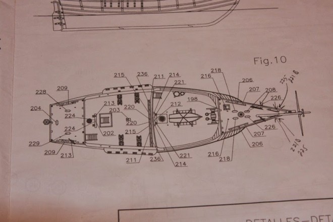
Before I could layout where the cleats, rails, and sheaves (a small pulley the rigging passes through) I first had to layout the standing and running rigging and where it would terminate on the different decks. Once again, I turned to Pastor’s book to compare the best guess for the rigging with the plans supplied in the kit.
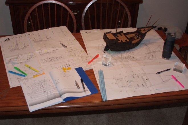
To my surprise, the rigging plans supplied in the kit were quite accurate when compared to Pastor’s rigging. There were however extensive differences between the two when it came to belaying the rigging to the deck. Using the plans supplied, Pastor’s work, Mondfeld’s “Historic Ship Models” and “Vanguard of Empire” by Roger Smith (which contains some of Columbus’ actual notes) I put together my own ‘best guess’ of the ship’s rigging. I then drafted a mockup-up of the ship’s deck and where cleats, sheaves, rails, and deck rings will be located to facilitate the rigging.
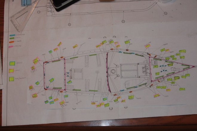
My new layout is color coordinated to reflect rigging to and from the Mizzen, Main, and Foremast / Bowsprit areas. It is only after the creation of the new schematic that I can create the fittings and place them on the ship.
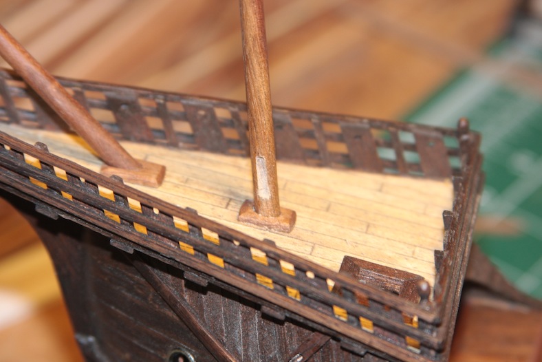
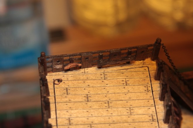
Main Mast RailMost ships have a main mast pin rail to secure rigging from the main mast. The Santa Maria is no different. However, as I mentioned, belaying PINS were not in existence for another century. This was one of my initial mistakes. My first railing contained pins, so I had to go back, take it out, and replace it with a rail with no pins.
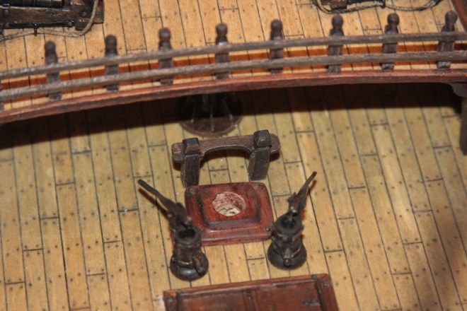
The new rail is the built essentially the same as the previous rail and consists of two 4mm x 4mm beveled stanchions and a 5mm x 1 mm walnut piece shaped and notched.
The cleats supplied are rather delicate metal pieces. These actually work fine to add to the sides of the masts (a feature missing altogether in the kit instructions) but are wholly inadequate as deck and bulwark fixtures.
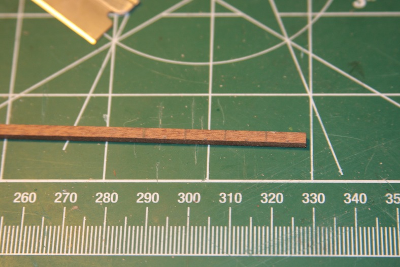
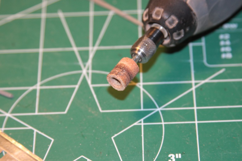
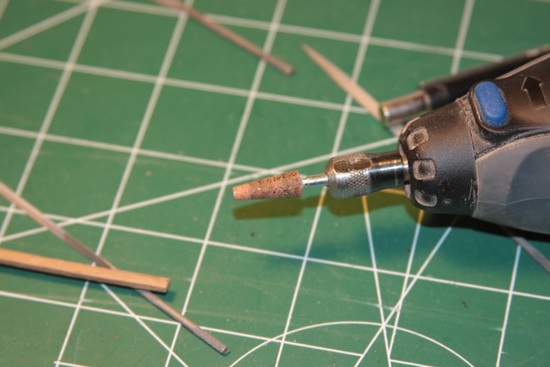
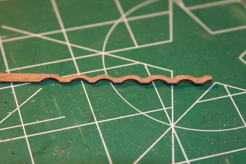
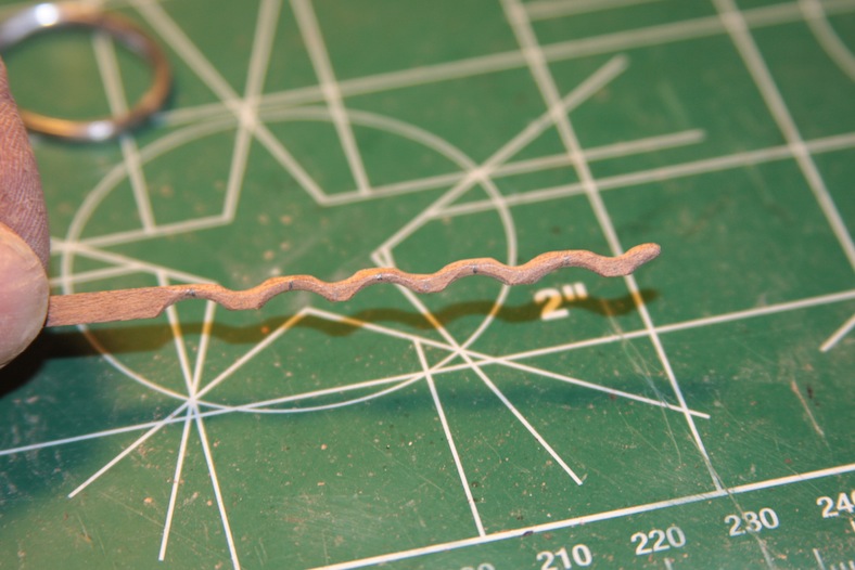
I briefly considered ordering cleats from one of the supply companies that I use, but decided I would be better served making my own. At any rate, I used a very similar process starting with a 3mm X 2mm strip, measuring off every 10mm for the width of the cleat I needed. I used a 10mm Dremel grinder for the bottom of the cleat and a 3mm to 7mm conical shaped grinder for the top.
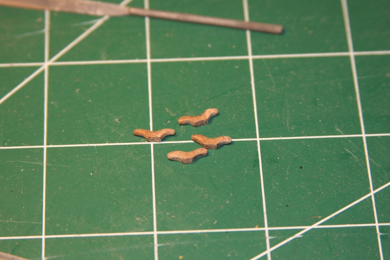
I then sanded and rounded the edges with 400 grit sand paper. I did this BEFORE I cut them apart since sanding any kind of small piece is much easier for me if it’s still on a stem.
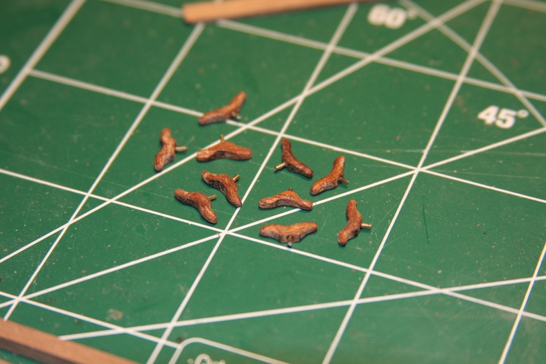
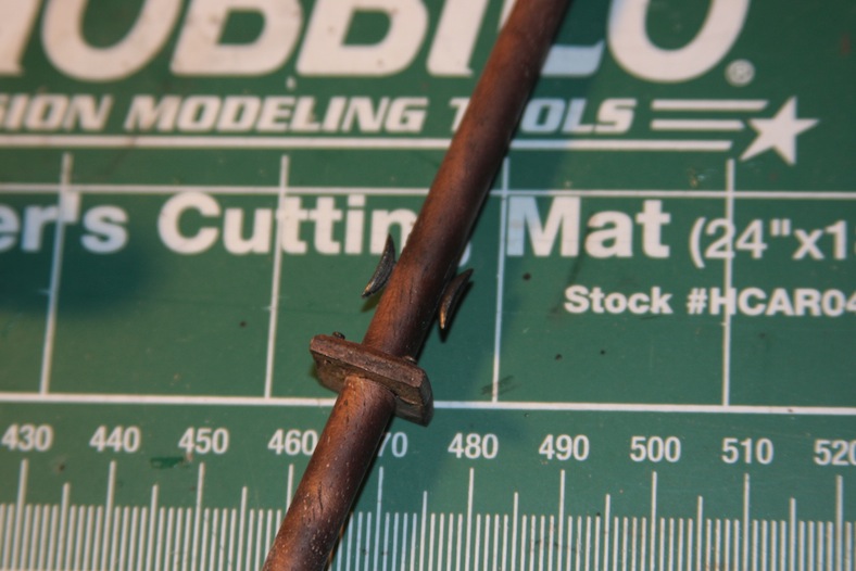
It’s important that these cleats are mounted to the deck with enough integrity to hold stiff rigging. To ensure that’s the case, the final step is to drill holes in the bottom of the cleats and insert a pin that will secure the cleat to the bulwark or deck beyond just glue.
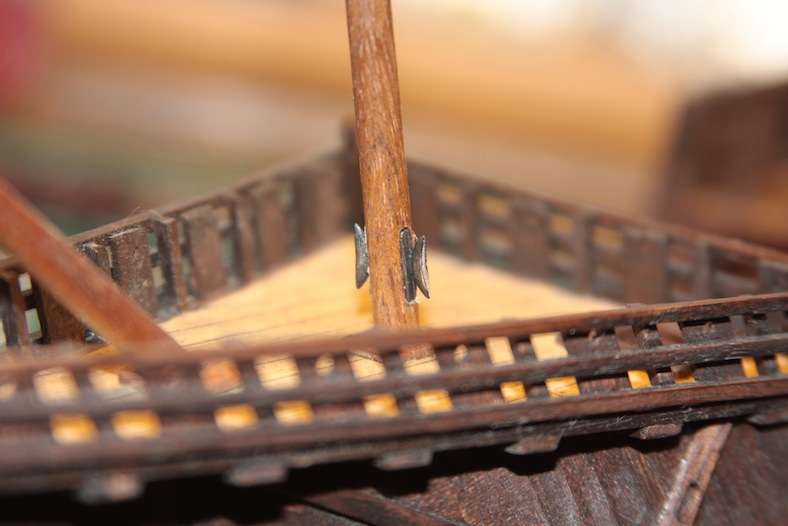
Additional cleats are attached to the base of the three masts. For these cleats I notched out an area at the base of each mast and used the metal cleats supplied with the kit.
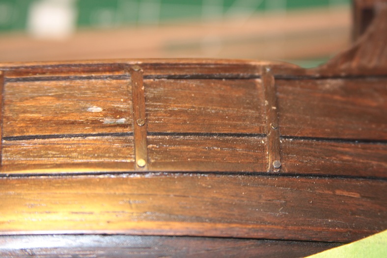
For the most part, sheaves are completely missing from the original rigging plans. My guess is that it is because these delicate fixtures are pretty darn difficult to achieve. The AL version of the Santa Maria is not billed as an “advanced” build, so it’s logical that they would leave out some of the more intricate details that would be too difficult for a novice builder.
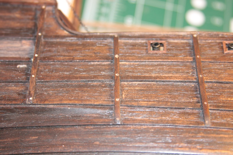
Essentially, a sheave is a wheel or pulley mechanism built into either a block or into the ship itself. Rigging lines are run through the sheaves to ease the ability to reeve the lines. According to my rigging research, the Santa Maria has five sheaves on each side of the hull.
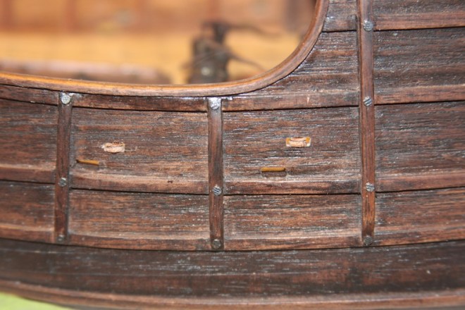
To build in these sheaves I used the same basic process as the sheave blocks. I drill to mark the locations, carve out the space, then insert the small disc that serves as the sheave itself. It ended up being extremely difficult to cut a dowel into a thin enough disc to fit into the hole carved out. My suspicion is that during the rigging process, I’ll need to drill out a slightly larger hole on the edges of the sheave to fit the rigging through. It will very much become a ‘threading the needle’ process.
The bulwark rails are simple features created with 2mm x 2mm strips of walnut secured with mounting brackets also made of walnut. Like the cleats, these rails must withstand rigging knots, and so are also secured to stanchions or bulwarks with metal pins.
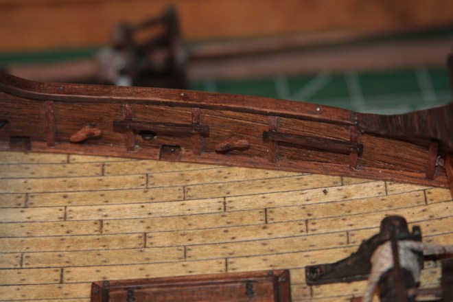
One of the challenges I faced was installing the rails on the poop deck while maintaining enough room for the deck to open so we could see the captain’s cabin. If I had the proper foresight, I would have made this measurement BEFORE cutting and hinging the deck. However, since that wasn’t the case, I needed to adjust the depth of the railings instead.
The standing rigging whose primary job is to hold the masts in place are called the shrouds. The main mast shrouds are attached through planks attached to the hull, then secured to the hull itself. Attaching these rails drew my attention to an aspect of the futtock riders that I overlooked earlier in the build – securing them with larger trenails. An oversight that I took this opportunity to correct.

Hi Sean, I find myself completely confused with where to start and how to go about the Santa Maria's rigging. Could you provide some close-up photos revealing what goes on below and inside the crow's nest?Regards Christiaan
LikeLike