Shipbuilder Sean Lehman recreates historic sailing ships based on original plans and techniques.
Category: H.M.S. Pegasus
H.M.S. Pegasus, a 28 gun sixth rate frigate launched in 1779. The 1779 ship was most notable for having Prince William Henry (who would become King William IV) as her Captain for a brief time.
It may seem obvious at this point – but the Pegasus is a three masted ship. The masts, from bow to stern, are the Foremast, the Mainmast, and the Mizzenmast. The sizes of each are determined by the overall size of the ship. These calculations are laid out in the several times mentioned 18th century books by David Steel. According to Steel, the main mast of a Swan ship would be about 63′ high and about 18″ in diameter. The two other masts are then balanced against that. I won’t go into all the specific measurements here, but I sketched out the 1/64 scaled down version of the masts starting with the main at about 300mm total – some of which would of course be unseen below deck.
Each mast is broken down into several sections. The masthead at the top forms a frame upon which the topmasts will rest and be secured. Next the ‘hounds’ (which are also sometimes called ‘bibs’ form the foundation for the mast tops; the small platforms upon which sailors would stand watch or perform other duties. The mast tops are the more contemporary version of the old school “crow’s nest” of which most folks are familiar. The hounds/bibs make up the top portion of the mast “cheeks” – two long braces on each side of the mast that give it additional strength and stability. The cheeks are nailed in place against the masts but are also held in place with wooldings – hoops and ropes that wrap around the cheeks and masts to once again create additional stability.
So with all that – let’s get on to the building of the masts. I started by size, thus the mizzen at the stern of the ship. Step one is to get the mast in the lathe and taper it just a bit from deck to masthead. There really isn’t much taper to each of the lower masts. Next up, the middle of the masthead is cut down and squared off to mark the location where the cheeks begin and the bibs will be mounted. The rest of this masthead will be filled in again later. The cheeks are added at this point; worth nothing that the mizzen cheeks only extend down a few feet whereas they will extend 2/3 of the way down the other masts.
The bibs are mounted against the top of the cheeks and nailed into place. Two strips are added to fill out the masthead and steel wraps hold them in place. I’ve simulated these steel wraps by using thin strips of electrician’s tape. Additional vertical ‘battens’ are then mounted against those iron hoops to hold them in place. Just below that, the trestletrees (running fore to aft) serve as half of the base for the mast tops. The other half of the base (running port to starboard) is made up of the crosstrees. Small ‘bolsters’ are added to each trestletree where the shroud ropes will wrap around the masthead and extend down to the deadeyes on the sides of the shop. Then the entire top section is painted black.
The wooldings have bands that support the top and bottom of tarred rope wraps. I simulated these hoops by using thin strips of a manilla folder painted brown. The woolding wraps are .45mm hand made rope.
The Foremast and the Mainmast are very similar in process to the mizzen and have all the same elements. As mentioned before, the key difference is that the cheeks run 2/3 of the way down each mast. I am also able to add an additional detail to the longer cheeks – the nails that run up the sides and in between the woolding wraps.
The only distinguishing difference to the main mast is its increased size and the slightly more pronounced roundness of the cheeks.
I mounted all three masts in place (temporarily) to get a view of how the picture comes together and how they size up against one another.
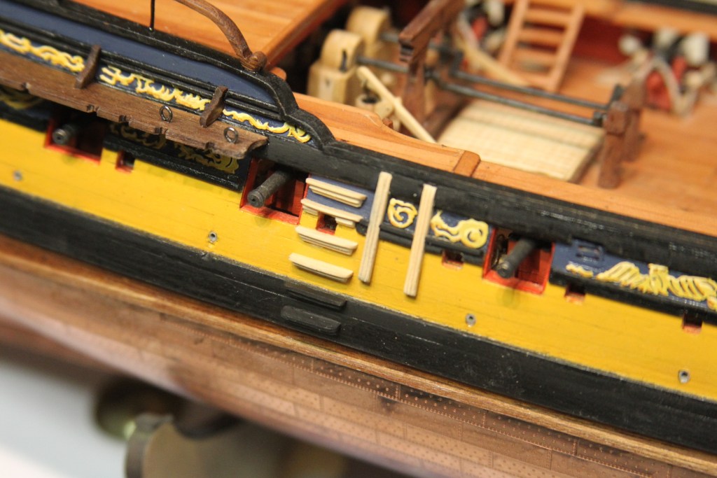
An age of sailing ship’s boats – or ‘life boat’ as most modern folks are probably accustomed to hearing it called – were as varied as the types of vessels and their captains. The shape and size of the small boats varied immensely ranging from shorter round “cutters”, to arrow-like pointed “yawls”, to a more generic “launch”. For the Peg, I chose to go with the same small boat as was mounted on the USF Confederacy – the long, slender Pinnacle. I felt as though the sleek lines and rounded front fit perfectly with the sleek lines and elegant shape for which the Swan Class ships such as the Pegasus were well known.
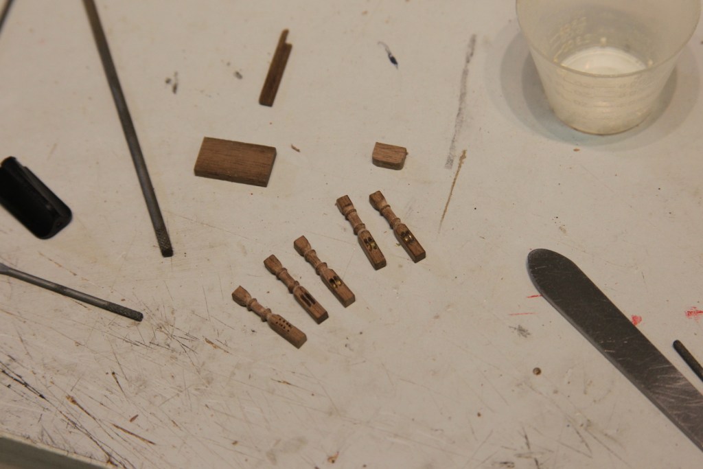
That said – before I could build the ship’s boat, I had to create the area where she would rest. The ship’s boat on Swan Class ships rests across the waist (the middle of the ship) on top of two spare top masts. Creating this masts was a great opportunity for me to practice my technique for the fore and main masts to come later. I used two different types of wood for the fore top mast and the main top mast respectively, and the first one turned out with much to be desired. It was an extra dowel I had lying around and I’m not even sure what kind of what it is – but it was too dense, very difficult to shape properly. The second was a basswood dowel which turned out much better. Which gives me a plan for the “real” masts that will come later. As others have pointed out, the kit plans for the top masts leave out some detail, so I did some research with David Steele’s 18th century bookson seamanship and rigging and drew out my plan for the top masts. The books provide exact dimension for rigging and masts – all you need to do is a little math to convert to scale.
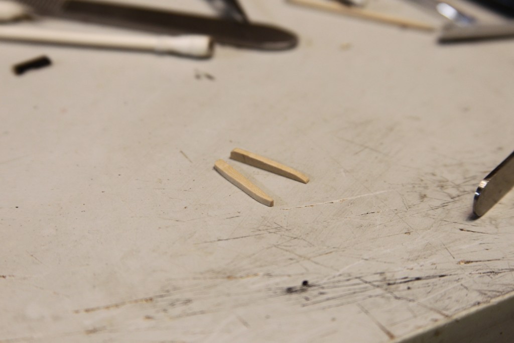
Each mast has several sections to it – some square, some octagonal, some round – and Steele’s dimensions lay it all out. There are a couple of basic methods for creating masts in general, and masts with different squared off areas – you either start with a square piece of timber and round it off, or start with a round dowel and square it off where needed. I am more comfortable doing the latter.
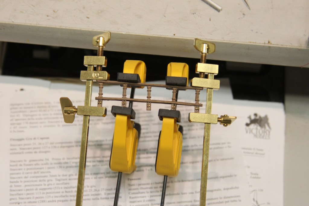
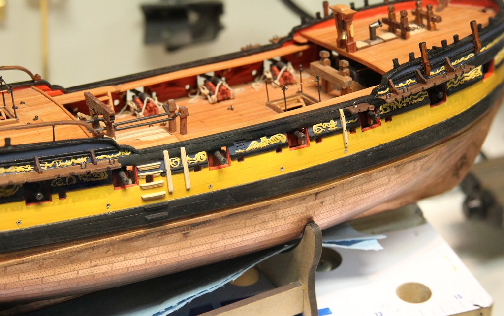
If you start round, you of course have to start with a dowel a bit larger than your final product to accommodate the square and octagonal areas. In all honesty, my first two attempts at these masts are pretty rough under scrutiny – so I was grateful they are painted on British vessels. Once painted, the spare masts are mounted along the waist atop the gallows and resting on either side of the belfry. After the spare masts were mounted, I went ahead and added all of the 1/2 pound guns and took stock of where she was after 600 hours of work.
With the spare masts are in place, I could start work on the ship’s boat. Since the Pegasus and Confederacy are both 1/64 scale, I was once again able to base my Pinnace on the materials gathered from the Confederacy. I borrowed the bones from the Confederacy Pinnacle, then went scratch from there. The keel was pretty easy to duplicate – but the bulkheads not so much without a laser cutter or some kind – so I just outright stole the ones from the Confed kit. A couple of things I did a little differently as I built upon the keel and bulwarks – I glued a strip to the top of the pieces that’ll later be removed. This adds LOTS of stability to the boat as you plank it. Otherwise, the much smaller pieces tended to wiggle around and get out of place – and yes, that crooked one was fixed first. Second – I actually double planked this little bad boy. The thin, narrow planks are really tough to get flush as you taper and shape them. Double planking gives me the opportunity to fill in some gaps with filler, sand smooth, then get the second layer of even narrower, and thinner planks really nice.
After the bulkheads are thinned and much of them are removed to reveal the frame, they are sanded even. Then the seat supports, floor boards, gunwales, and planking are added. For these parts I went with Swiss Pear to create a nice contrast against the boxwood, but to also match other parts of the Peg herself. This is a technique I used on the USF Confederacy and really liked.
The seating and oar locks are all boxwood – mostly because boxwood is the only timber dense enough to accommodate the delicate sanding. The oar locks were shaped with a needle file in one strip, then cut off before being glued to the boat. The rudder parts are brass shaped and blackened. Interesting note – the little round ‘handle’ on the tiller is a tiny bead that’s called ‘caviar beads’. Apparently they’re used as decorations on women’s fingernails. They were the smallest bead I could find on Amazon a while ago.
Many of the ship’s boats of the time were painted white along the hull, but once again I am choosing to leave the beauty of the natural wood color. However, I did decide to paint the sides of the pinnacle to match the same dark blue that is along the gun ports of the Pegasus. She’s then test fit in her place along the waist.
Next up are the bits and pieces that are stored inside the pinnacle; including a couple of harpoons, a grappling hook, and the six oars to match the number of oar locks. For the harpoons there are photo-etched harpoon tips that are blackened. To create the harpoon itself, I sanded a dowel down to approximate diameter, then cut a notch into the end to hold the head. Then I wrapped it in place. This is based on both my ship research and my anthropology research for the time period. These photos are a bit deceiving, but those 1/64 scale folks know just how small these buggers are. I used a jeweler’s saw with the smallest blade I had to very gently stroke back and forth and create the notch.
The grappling hook is pretty straightforward, the photo-etched pieces glued, blackened and then attached to a coiled rope dabbed with some diluted white glue to hold it in place.
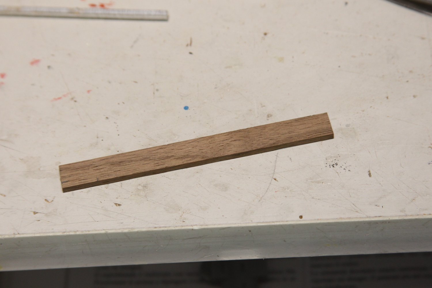
The oars at this scale a BUGGER. I started with a 5/32 x 1/32 piece of walnut. I used walnut instead of boxwood because once again I am paying very particular attention to my color schemes, and I want the oars to stand out from the launch, yet blend with the other walnut deck fittings. Anyway, I mark off the length of the paddle, and rounded and squared off portions of the oar. Then I trim/sand the handle square, only to finally round out the portions in the middle. Lastly, I thinned down and shaped the paddle ends. I think I ended up doing about ten of these – at least a few of which broke – to end up with the six that I wanted. This is a very slow, gentle, and tedious process of sanding. I’d guess that I probably devoted about an hour to each oar.
My ‘mounting’ technique in terms of where and how to place the items is a combination of organization and haphazard-ness. In other words, I don’t like an OVERLY organized or militant look to things, because it feels unnatural. Yet, I don’t want it to appear as though the crew is completely void of discipline. First, the spare top masts are strapped down with strips of rope, and the pinnacle is secured similarly. Finally, the oars and bits and pieces are stowed and glued in place. I threw in an extra coil of rope for good measure.
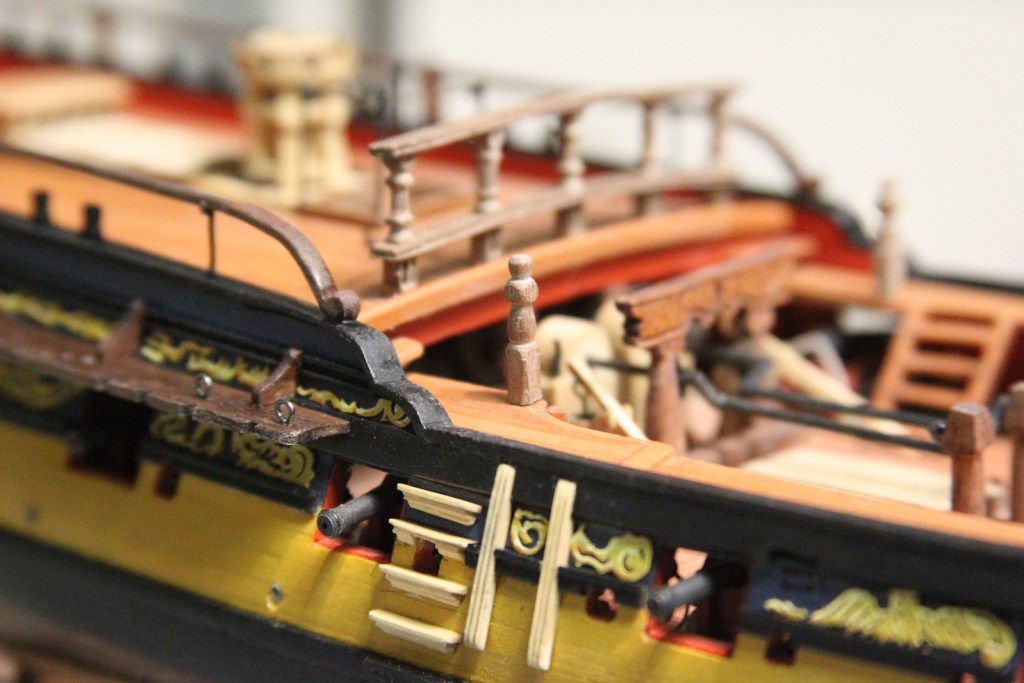
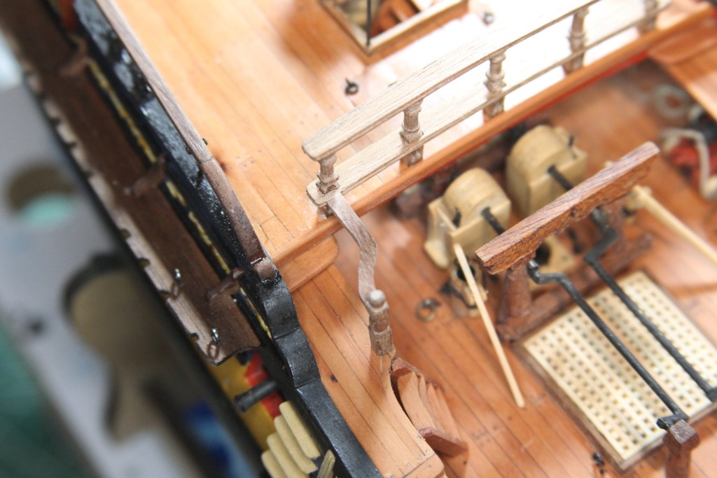
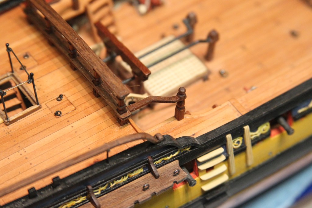
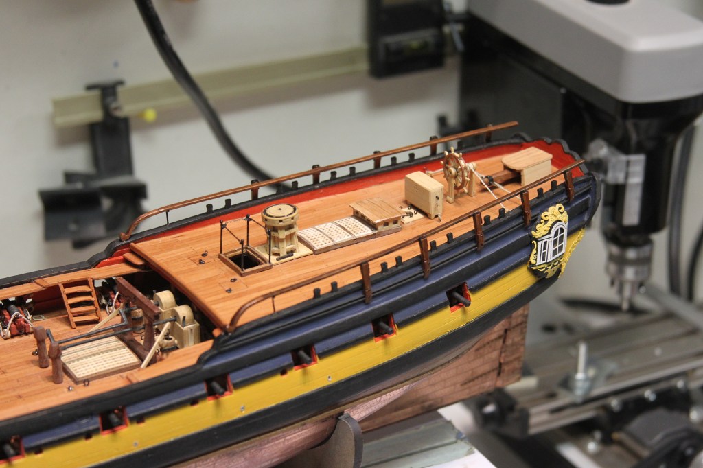
Anyone who has seen an historic sailing ship in person becomes immediately aware that space on these vessels (regardless of era or class) was at a premium. As such, spaces aboard had a variety of simultaneous uses. The 1776 HMS Pegasus is a Swan Class sloop with a 96 ft length on the gun deck and a 26ft beam (width) and held a compliment of around 125 sailors and officers. While shifts and watches overlapped and varied, all those folks had to sleep somewhere. The ‘where’ was on hammocks hung below decks when used, and stowed elsewhere when not used. Many of them were stowed using hammock cranes that stretched along the sides of the ship – as shown in the photos below.
While I don’t intend to create hammocks and load the cranes with them, it is important to include the hammock cranes as a detail. There are also varying sources that illustrate exactly where the cranes were located – whether along the waist, forecastle, or quarterdeck. Once again, I chose to follow the references from The Fully Framed Model series on Swan Class ships and located them along the quarterdeck parallel to the railing. I started by cutting and bending lengths of 1mm diameter brass rod then flattening one end. My method of flattening is putting the end in the flat part of needle nosed pliers (the smooth area NOT the ridged area) then laying the pliers against an anvil and give it a couple of good whacks. The flattened bit does need to be shaped a bit afterward so that they’re all consistent width. I stuck a couple of pins in either end of the rail and ran a thread so I could measure the necessary heights of the stanchions as they ran alongside the railing. It’s important to ensure that the height of the hammock cranes falls short of the 1/2 pound guns – also figuring in the loops that are to be soldered to the top that facilitates the line. Stanchions are cut to height and a small bit of a 2mm brass tube is soldered to the top – same method as other railing stanchions on the ship.
Everything is blackened and mounted. A couple notes – I kept all the railings in order of height as I blackened them, which was a bit tricky. But I didn’t want to mix them up after I’d measured them all. I mounted them with a ‘bolt’ through the center of the flattened area. Technically, I should have used two bolts, but at this scale that was too much to ask. The fore end is knotted at the stanchion. Technically (again) this should have been pulled down and mounted on a ring bolt at the railing, but my wood railing is a bit too far forward for that and it looked terrible, so I compromised. The aft end is seized at a ring bolt.
As an additional detail, I also added the entry ropes. While they are pretty simple – just a couple of ropes tied with knots to assist climbing up the latter – it was a bit tricky getting the small knots an exact and consistent distance apart. The stanchions at the top are photo-etched metal pieces that were intended to use in a different area of the ship.
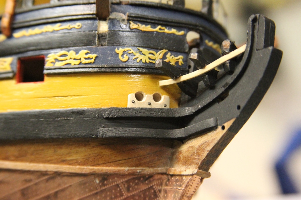
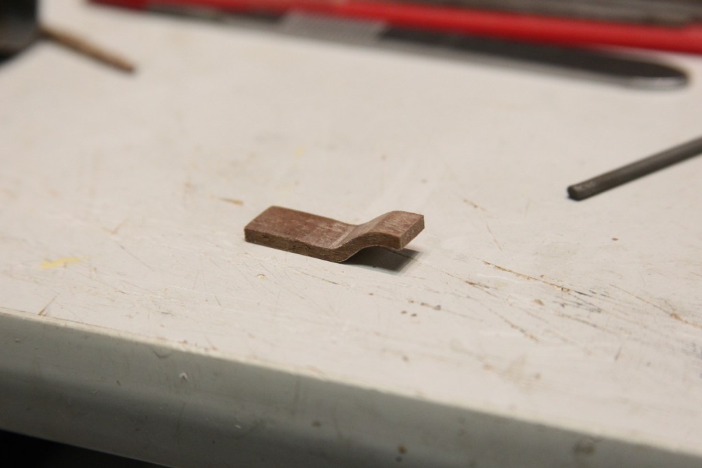
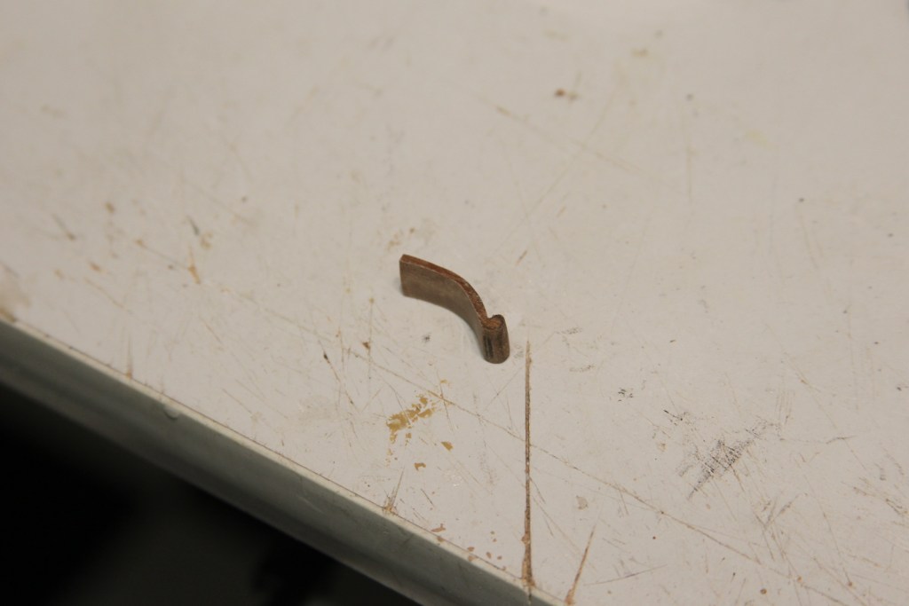
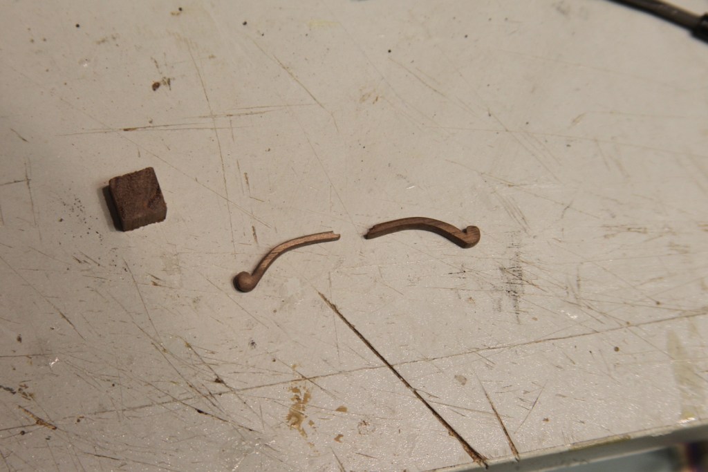
A ‘boom’ in nautical terms is a spar (another word for pole) that extends out from a rigged sail providing for a number of purposes including additional rigging and control. The boomkins are short booms that project from the bow of the ship and are used to secure a couple of larger main fore tack blocks. A notable aspect of the boomkin is that it has a slight downward curve which gives it additional strength. Getting this downward curve normally means one would have to either soak and bend a dowel, or create the boomkin from a solid block of timber. Fortunately for me, I happen to have a couple of extra laser cut boomkins left over from the USF Confederacy build. Although the dimensions between the ships are different, the scale is the same and so these saved me a bit of work.
I did however have to make up that extra work when I discovered that my seats of ease were just slightly off – about a half millimeter to be exact. The boomkins run right along side the sides, so although I did measure for this – being off by even the slightest is no bueno. Moving the seats of ease meant readjusting all the ledges. A little bit tedious, but necessary.
The capsquares which hold the boomkin to the rail are cut from brass and shaped by curving them over a pin file handle. They’re then drilled & blackened, then mounted on the boomkins.
Next step for the bow was the berthing rail. I followed the same procedure here as the foc’sle by soldering a brass tube to a pin head, filling it down and running the same cabled wire through it. I still dig how this ‘railing’ looks as compared to using a line or a straight metal rod. However, I think this will preclude me from adding netting to the bow because I think that will look funky. I may change my mind after mulling it over as the netting can be added at any time.
Rigging the boomkins consists of three lines that extend out from the end of the spar – the larger fore tack that I mentioned at the beginning of the post and two shrouds that attach the boomkin to the hull and knee of the head (the portion of the front of the keel just below the figurehead). The fore tack block is one of my larger (6 mm) boxwood single blocks sanded down to create the shoulder block look and the served line for the strop that wraps around the block and loops over the end of the boomkin.
The aft shroud also loops over the end of the boomkin then attaches to the hull with a pretty simple hook into an eyebolt. The fore shroud is a bit more complicated with a triangular eye bolt strapped to a heart block and lanyard. The eye bolt is a bit of wire angled into the triangle with the end soldered then attached to a standard eye bolt. I don’t remember where I got these laser cut heart blocks, but after a little sanding they worked out well. Strapping the heart to the triangle without it looking like a just a big lump of line was a bugger however. For the second shroud, it made much more sense to do that part first, then loop the other end over the boomkin and finish the shroud.
The spar that extends forward from the ship’s bow is called the bowsprit, and is one of the most notable (and I think cool) aspects of a fully rigged ship. That said, on many builds and kits the bowsprit is over simplified for ease of construction. In reality, by the mid to late 1700s, the bowsprit had become and complicated piece of engineering and rigging. As with the rest of the build, my intention with the bowsprit is to added those addition complications to provide as much accuracy as is feasible at this scale.
The spar itself is a round dowel, however it squares off at it’s tip so that ‘bees’ can be fitted and a jib boom can be added. The square end of the bowsprit is often overlooked in kits and instead both the bowsprit and jib boom end up being rounded off for simplicity. There are a couple of way to achieve a round mast/spar with a square end; either start with square timber and round off the rest of the mast, or start with a larger size dowel, square off the end, then taper the rest down. I chose the latter method.
However, first, I needed to measure out where the taper and other aspects would need to take place. The base of the boswprit narrows, enters the bow, then is secured in the supports on the main deck below the forecastle. I used a dummy dowel to measure out the distance to these supports, as well as lining up where the gammoning (the ropes that secure the bowsprit to the ship) would take place in the headworks. These areas are marked on the dowel that will become my bowsprit.
The fore end of the bowsprit is sanded to square with the top three sides extending slightly longer than the bottom. The whole thing is put in a lathe and tapered at both ends until the fore end is slightly smaller than the square and the aft end fits into the hole at the bow of the ship. That same aft end is notched to fit into the support on the main deck (which we cannot see at this point, but can be seen in this post).
Now that the bowsprit is in place (at least temporarily) I am able to finish a couple of important elements on the forecastle – the bowsprit partner and the breast hook. I fashioned the partner from planks of Swiss Pear so it would have the same look/feel as the deck. I cut out the space for it, then added it in place. Worth noting is that the partner would most likely have been a single piece rather than planks glued together as I have it – but I’m pretty much out of Swiss Pear, so I’m adapting; and I didn’t want to use a color wood that was vastly disparate. Second: Also, most of this will ultimately be obscured by the breast hook and associated rigging.
The breast hook is fitted against the foremost bulwark of the forecastle and houses a number of cleats for rigging the bowsprit and other elements near the front of the ship. First, I measured the curvature using a piece of cardstock, then cut the breast hook from pieces of Swiss pear glued together to achieve the proper thickness. The piece is mounted with ‘bolts’ along the front.
The small cleats are made from boxwood and initially shaped by a round dremel tool before using small bits of sanding paper and sanding sticks to give them their final shape.
The base of the bowsprit is fitted with gammoning cleats which will hold the wrapped line in place where the bowsprit is secured to the ship through the headworks and a hole in the keel. Just behind the cleats is a ‘saddle’ that contains a set of holes to facilitate additional rigging.
The fore end of the bowsprit is fitted with ‘bees’ and a ‘cap’. The bees are a set of wide sheeves (pulleys) for the running rigging and the cap allows the jib boom to be joined. The cap is a rectangular piece with a square hole that fits over the bowsprit and a round hole that accommodates the jib boom. In addition, the edges of the cap are angled to match the overall lines of the bowsprit. Finally, the cap also contains a rounded notch that will fit the “jack stay” – or small flag pole at the front of the ship. The bees are flat planks to either side of the bowsprit bolstered by blocks on the bottom and then fitted with two sheeves on each side. The other two elements on the front of the bowsprit are the jib boom saddle (where the end of the jib boom will rest) and the ‘woolding’ – a wrapping of strong line that strengthens the end of the bowsprit. This line is wrapped between two rings which I have simulated using electrical tape. The entire fore end of the bowsprit is painted black and final elements are added – a series of eye bolts and the woolding line.
The bowsprit is secured onto the bow of the ship with the base inserted into the bow and secured in the aforementioned bowsprit bitts on the main deck. The gammoning lashes the bowsprit securely into place. After reviewing a couple of books to ensure accuracy, the gammoning consists of 9 to 11 wraps around the spar, twisting in the center, then feeding through the gammoning slot in the part of the keel called the “knee of the head.” As is stood, I could only manage eight wraps without looking funky – but the important aspect is that the number of horizontal wraps along the middle match the number of vertical wraps.
A note on rigging lines and color
I have decided to start making my own rope / line for this project which allows some flexibility and additional accuracy. It also allows me to adjust the color of the line to achieve what I believe is a more accurate build. Most people have heard that the the running rigging of a ship (which was constantly moved, changed, and adjusted) has a lighter look, while the standing rigging on a ship (which was rarely adjusted) was tarred to provided protection thus giving it a dark look. This “dark” look is most often – almost always in fact – represented by using black line. However based on the research I’ve done, the standing rigging for British ships were often soaked in “Stockholm tar” which apparently had a more rich brown color. That’s the option I’ve chose for this build, hence the brown color on the gammoning pictured above.
And here are a couple of gratuitous shots of me turning my own rope.
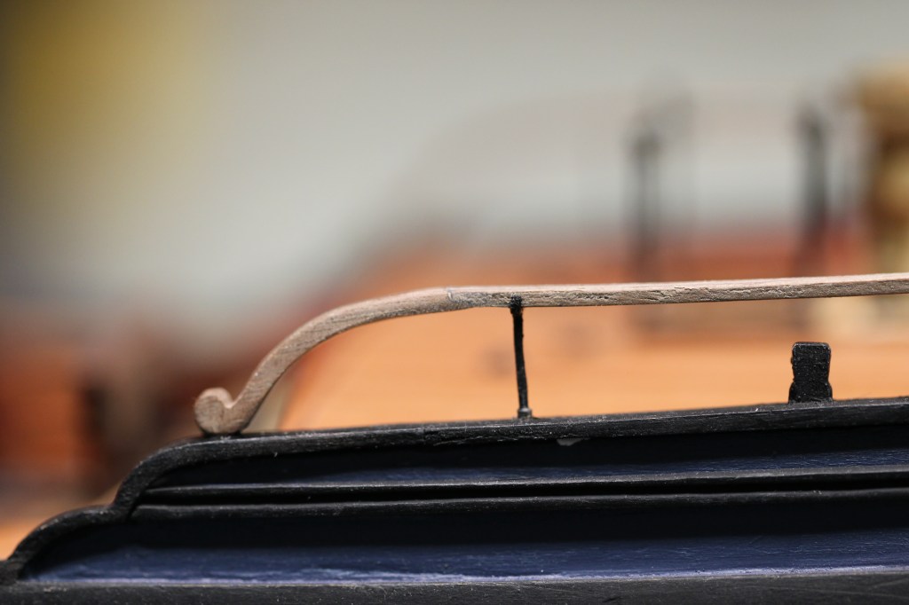
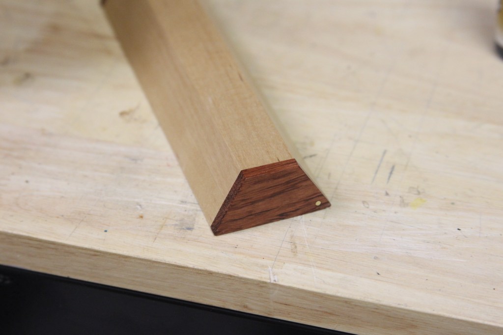
Contrary to the how the name sounds, the ‘fish davit’ is not actually used for fishing – at least not for catching sea critters. Instead, the fish davit is used to help ‘fish’ out the extraordinarily heavy anchor for stowage. The davit is a large, square beam fitted on each side with rope handles to allow multiple crew members maneuver it into position. The davit is tapered slightly from the center outward with crowns cut out on the ends to fit and secure rigging. One end of the davit hangs over the side of the deck and is held at the opposite end by a spanshackle securing it to the forecastle and providing leverage to haul up the anchor.
I began with the large, square spanshackes by taking a round brass rod and sanding the edges square on both the inside and outside a loop that is measured to fit the davit. They are chemically blackened then secured to the forecastle with a ring bolt.
The davit is pretty straightforward to shape, merely a square piece of timber cut and tapered. However the hand rope is a bugger to get correct. The rope is secured along the davit with looped knots of line rather than metal rings. To create each loop I drilled a hole in the davit, added a small bit of super glue to stiffen one end of a rope so it can be inserted into the hole. Then, I stuffed the other end of the loop into the same hole using needle nose tweezers and a dental pick. The davit is then mounted on the deck and in the spanshackle. At this point, it’s not permanently mounted in case it needs to be shifted around to get at any rigging, etc.
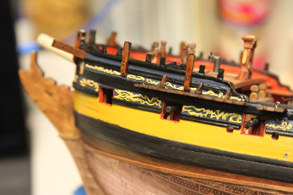
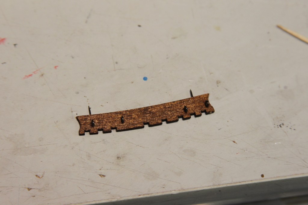
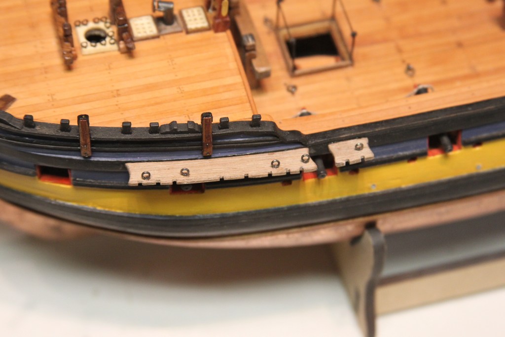
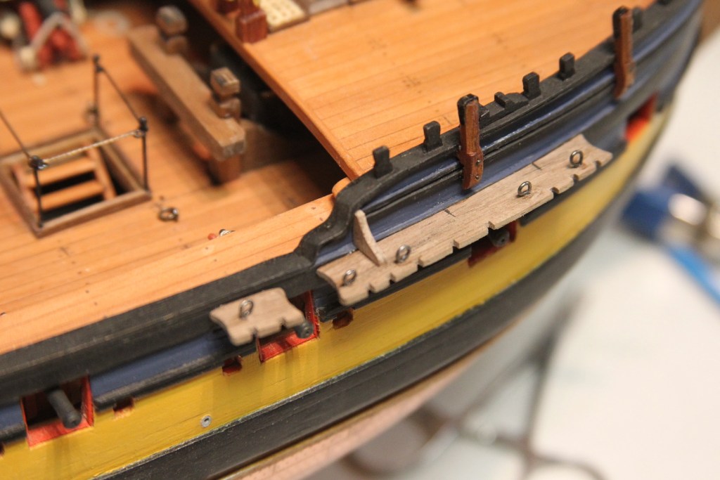
The billboard is a relatively small detail that I have rarely seen added to builds, but provides a very nice additional detail. The name belies the purpose, as it’s not intended to display any sort of information or advertisement as one might assume now days. Instead, the billboard protected the sides of the hull and the chain plates from the extremely heavy anchor as it was pulled up and stowed.
A second layer of planking is mounted to the main wales for protection using 1/16″ x 1/8″ strips of basswood. Though softer, basswood is easier to work with and is ultimately painted black to match the main wales so the difference in texture is unnoticeable.
The rest of the setup is comprised of a flat ‘bolster’ along the main wale just below the preventer plates, two stanchions that support the planks from the bolster to the channels, then the planks themselves. I used boxwood for the bolsters, stanchions (1/16″ x 1/16″) and planks (1/16″ x 1/8″) so that they would match the other hull fixtures (such as the fenders, etc) after being coated with wipe on poly. Final touches are the blackened bolts that mount all the planks to the wales and stanchions. Though there were likely two bolts per plank, this small scale only provides enough room for one.
The ‘waist’ of the ship is the area between the quarterdeck and the forecastle (foc’sle), which was open on ships of this size and era. The gangways provided a means for sailers to traverse this area without having to run up and down the stairs and across the main deck. However, it was necessary to have some semblance of safety or sailors would have likely been tossed over board each time the ship dipped in a heavy swale. The waist rails provided this sanctuary of course. There is some flexibility here, as some waist rails were just a rough strip of wood mounted on stanchions, while others had some kind of netting. I chose the latter as it is illustrated in the “Fully Framed Model” (FFM) series. The first step was to come up with the rough rail on stanchions. I used an oak strip to match other deck rails and stanchions.
I’d been noodling through how to make the netting along the waist rail and spent quite a while looking for a good “fishnet” representation – even going so far as to ask my lovely wife if she had any ‘delicates’ lying about that were no longer in use. I found a couple of ‘acceptable’ options at a fabric store, but nothing that I was really happy with. None of them looked like “rope” but rather just laced thread. Which meant coming up with my own version.
First, I tried weaving together my own netting using Dan Vadas’ example from his Jib Net here. My attempt wasn’t great.
This is after something like 6 hours mind you, makes tying off ratlines feel like a breeze. After all that, I still wasn’t digging it. I think it looks fine – and I may well still use it for a Jib Net, but I didn’t like it for the waist. So, after more research I found a good video on youtube and illustrated traditional net making for fishing. Though challenging, the method was transferrable to a much smaller scale and I was able to replicate it using .20mm rope. Here’s a shot with my first attempt on the bottom – which was pretty sketchy but a good practice to get the hang of it and improve my method. In the top one, I used more pins to hold my tiny work in place and thus create more even loops. I didn’t use any sort of net needle, I just used rope with the end stiffened with CA glue.
It still took 6 or 7 hours each to complete the netting which ended up being about 113mm long by 11mm wide. I then mounted it to my waist rail by first using a tiny dot of CA glue to attach the loops to the rail and stanchions, then tying off the loops to the stanchions, and finally looping and tying off another length of rope around the rail itself. I’ve seen other example of this looping on rails in this time frame – usually metal ones to create a better grip on the rail when wet. So I figure it too much of a stretch to have seen it on a waist rail.
Finally, it’s mounted on the waist. Last touches were to add another tiny drop of CA glue to hold the bottom loops even with the ship’s rail. Overall, this was a boatload of work (no pun intended) for a relatively small area and detail; and I still think it’s still a touch out of scale (especially the knots), but it’s about as small a rope as I could go and still successfully work the pa. But I’m much more pleased with this than I think I would be with a more modern alternative to netting.
I’ve always loved the name “deadeyes” – because of course the round rigging blocks that facilitate the shrouds look just like blank faces when oriented properly. The materials provided make pretty easy work of the deadeyes, binding, chains, and preventer plates on the Peg. The deadeyes fit into pre-shaped binding which is opened, fitted with the deadeye, then closed up. The chains are slotted to fit over the binding, then the bottom of the chain is attached to the hull with a preventer.
To properly align the chains, one typically needs to add the masts first. Then, the shrouds (which stabilize the masts and create the ratlines) are fed down to the hull and the angles of the chains line up with those shrouds. However, I am able to provide a ‘best guess’ based on the alignment of the channels and gun ports. That said, some adjustments had to be made for the gun ports, sweep ports, and even a couple scuppers. I also used slightly larger pins/nails as they needed to be functional as well as decorative – in other words they need to hold tight once the shrouds are run. After the deadeyes and chains were in place, the channels are capped with a thin strip of walnut scraped with a corner portion of one of the AL scraper edges.
The studding sails (also called stun’sl) were additional sails that were spread out on the sides of the hull to add increase speed in fair weather (see image below).
USS Monongahela with studding sails set. Courtesy: Wikipedia
The stun’sl was attached to the stun’sl boom which was mounted on the channel with a pin on one end and a hook on the other to hold the boom when not in used. These two pieces were called the boom irons – one set on each side of the main channels. On my peg, they’re shaped from brass, drilled and blackened, then mounted with blackened nails / bolts.
A final addition are preventer bolts in between the chains and swivel bolts along the hull. These stays and bolts were used as a backup in the event that a shroud or deadeye failed or otherwise needed to be adjusted or if there was need to jury rig something.
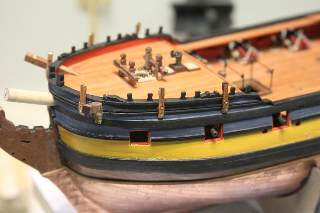
The gun ports are the openings along the hull and waist that provide access for the guns (of course). There is much debate about how many of these ports actually had lids, and what ports did not. I’m opting to go with one gun port lid on the aft-most opening, as this opening would have been accessed in a cabin. The other ports (particularly those along the waist) would have been open to the elements, and a gun port lid would have provided little benefit.
The fore most port is the Bridle Port, and different from the rest as it served a more specific purpose. Its main function is to assist with the tackle attached to the anchor when it broke water. The bridle port also served as ventilation for the foredeck (which housed the galley) as well as serving as access to a recovery area for injured crew members. Because of its different purpose, the bridle port hinges are horizontal, with the door opening sideways rather than upward like the gun port lids. Finally (and this was a mistake on my part), the bridle port should have been shaped differently, with a slightly more ‘portrait’ opening vs. square like the gun ports. My mistake was cutting its opening the same as the gun ports.
All of the doors are pretty straightforward to create – two layers of planks the same size as the openings. The difficulty lies with the hinges. Rather than try to cut my own, I decided to use some parts that I hadn’t intended to use – the kit provided hammock cranes; as I’ll be making my own later. I cut the eyelets off of these bits, and repurposed them as hinges by lining them up and inserting my smallest pin.
I sharpened the ends of the looped portions to create pins, then inserted them into the doors and also the hull. Then I lined up the hinges on the door to appear as one solid piece.
It’s worth noting that the bridle port door has a bolt on the outside as the ring bolt is on the inside rather than eye bolts like the gun port lids as there isn’t a need to open it with a line as with the gun ports. I turned the gun port eyebolts from wire, fed them through the drilled out hole, then turned them again on the other side. This was a bit tricky using jeweler’s pliers and took some fiddling with tweezers once they were in, but created a more secure piece than trying to glue an eyebolt to each side.
Lids were mounted the same way as the bridle port with my manufactured hinges, then the rigging was added extending through two holes drilled just above the lid.
There aren’t clear records, however it is generally believed that larger scale figureheads began appearing sometime in the 1500s, and were prominent on British naval ships by the end of the 16th century. However, the belief that a carving or relief on the front of a vessel could ward off evil omens or serve as an offering to the sea dates back much further. One of the oldest museum models, The Coca de Mataró, features a Griffin-like head carving that served as both a symbol and a battering ram. Viking Age figureheads were not only weapons in and of themselves, but also perpetuated the notion that Vikings regarded their ships almost as living beings.
Regardless, it is undeniable that figureheads were of great importance and coveted and cared for by a ship’s crew. I wanted to give the Pegasus that same level of respect with her figurehead. While the resin cast figurehead that came with the Peg kit was fine, it had two issues I didn’t care for; I wasn’t impressed with the style of the wings, and it looked like every other Pegasus figurehead I’d seen on HMS Pegasus builds.
After spending weeks searching for solutions by looking at everything from ear rings to Christmas ornaments, I finally stumbled across this package of little toys at a hobby store that perfectly matched the scale.
I really dug the wings and the body, but obviously the cartoon-y head (and unicorn horn) left much to be desired. Also – there was no way the rear legs would work with the space available on the stem post. Finally, since it’s a little rubber toy – I wasn’t going to be able to manipulate it much and I was concerned about painting, etc. So… I ended up creating “Franken-Peg” – a combination of the kit figurehead and the one I’d purchased. The rubber was really receptive to cutting and gluing it together – and looked even better after a coat of primer.
Some final adjustments needed to be made after it was mounted, but I’m pretty happy with the end look. I’ve seen some good looking wood color paint expressions on figureheads, but I wanted to stick with the traditional white that was most common to the Royal Navy. So “Franken-Peg” has several coats of different shades of grey and white to give her a carved look and some depth. Most importantly, it’s definitely not a figurehead that will be seen on any other ship
The elegant and decorative head works at the bow of the ship are an intricate weaving of shaped wood that serves to facilitate the bowsprit, but also provides a distinct look to the vessel. For builders, it is a complicated area that is quite difficult, and so visible that any errors tend to be magnified. It is for these reasons that I’d been delaying work in this area. However, I’d delayed as much as I could, and the head works must now be tacked.
I’ve noodled through what I’d like to do here, and it’ll be based on the plans to form the foundation. However, the plans omit several aspects that are too complicated for most casual builders. This isn’t unusual for commercial plans, but does cut down on the accuracy quite a bit. On the Peg, I’ll fill in the grating, seats of ease, false rails, and other elements not included in the Peg plans. Most of these will be done in boxwood as it’s the only material dense enough to carve and shape this small.
I started with the three timber heads which extend from the knee (forward part of the keel that creates the bow) and support the grating and rails. The timber heads are cut from the plan pattern and shaped in walnut so they’re a bit sturdier. I wanted to slim then down and reshape them a bit so they look (hopefully) more graceful as it comes together. The plan versions look a little thick and I want a more gentle curve as they work their way up to the rails.
As you can see in the third picture, there is still some shaping to be done so that the rails fit smoothly along the sides. As a total side note – the bow doesn’t look as wonky and askew in person as it does in above middle picture. I focus stacked four different pictures so the timbers would be all in focus and sometimes when Photoshop “auto blends” the layers the rest of the photo can come out looking a little odd if you don’t use a tripod (which I didn’t).
Next up was the simple, yet always anxiety inducing job of cutting out the hawse holes. I marked them out and then used a very high speed drill bit to avoid flaking or other damage. The hawse holes set the baseline for where the cheeks will be mounted. They set on the upper and lower edges of the main wales. However, I did run into a slight issue. Once again, because of the way I mounted those main wales so that they would be more accurate, the cheeks now conflicted with the gammoning slots when I extended the hair bracket from the upper cheek. Not a huge issue, I just drilled out more room for the gammoning and added the hair bracket moulding.
The gammoning hole is just below the timber heads and facilitates a thick line that ties down the bowsprit.
The main rails are the trickiest and most difficult part of the head works. I chose to cut them from boxwood in three separate pieces in order to achieve the most consistent “swoop.” I used a card stock template to measure out the necessary distance and curvature, then temporarily mounted the two end pieces onto the bow leaving the space in between. This allowed me to fill in and custom fit the middle “wedge” piece into the gap. Once it was all snug, I glued it together and and sanded it down. It’s worth nothing that there is also a slight inward angle between the three pieces allowing it to guide along the bow properly
The main rails are set aside for now to get to the lower railing. First, a filler piece of walnut is added where the Pegasus figure head will rest. Then, the lower railing runs along, and actually cut into, the head timbers. This piece is measured and cut from boxwood and slots are cut into the timber heads.
The hawse hole bolsters are cut, shaped, and fit into position so that the rest of the lower railing can be measured out as they run all the way up to the cat heads.
Those lower rails are carved out with a curve in a similar manner as the main rails. The cathead support is carved, shaped, and fit also from boxwood. I then painted everything with my color scheme. I went ahead and gave this fitting a coat of paint and wipe on polyurethane before I progressed to the covering boards on the outer edges of the head timbers where there is going to be some VERY delicate painting, etc, and the coat of poly makes it much easier to clean up errant paint mistakes that occur as a result of my hands not being nearly as steady as the “good ol’ days”.
The covering boards are cut from my thinest stock and soaked before they are shaped along the head timbers. I did have to sand down the areas where the lower rail meets the head timbers to provide the necessary fitment. After they were dried and glued in place, I added a little bit of filler where needed and painted.
I heavily debated whether to add the little vertical strips of decoration along the covering boards or if that made it too busy. After a lot of holding it in place and debating, I finally decided that the added decoration somewhat detracts from my sketchy paint job. I REALLY had a hard time with those little yellow lines after trying to mask them off and everything else. I even tried using tiny strips of yellow tape but the color didn’t match the other ochre. I ultimately got the best results I could by just painting them free hand. The added vertical decorations also blend with the cheeks, so I’m cool with it.
Much of the grating is omitted in the plans as it’s quite a complicated endeavor. More complicated at such a small scale as 1/64, and I learned again that I needed to make some concessions and deviate from the exact plans for a swan class ship. I cut, measure and place each piece individually because my scratch made rails and timber heads were fractionally uneven. Fractions of millimeters don’t seem like much, but they become noticeable quickly.
I started at the base of the bow, added the most forward supports and braces, marked out the locations of the grates, then filled in the grates in between. The process was basically to cut it close, test fit, sand the edge literally three or four strokes at a time, then test fit again until it slid into place.
In the picture above there’s one piece of grating missing on the starboard side. That’s because I thought I glued it in place but didn’t then when I shifted the model to take the picture it fell out and I didn’t notice until I saw the photo. It has since been replaced of course.
Next the “seats of ease” are added – simple toilets for the crew (the captain and other officers would have their own facilities in the cabins. The seats are rather simple to make and sized to be equal to one another. I shaved off thin little bits of the grating to get them to fit into the bow so they’d remain mirror images of one another.
The false rails were decorative boards that run along the main rails and add some privacy and wind protection for those on the bow, particularly when using the seats of ease.
I started with a card stock drawing fitted to the head rails, then carved them out of boxwood. Knowing my scratch build main rails would not be identical, I cut the false rails with a little extra room on the bottom end so they could be fitted neatly to the specific curvature of each main rail.
The inner relief was carved out using my smallest Dremel engraving attachment then smoothed out using a pointed burr. The rails were then mounted and painted. A small amount of filler was used in the areas that didn’t match up perfectly.
That addition wraps up the head works with the exception of the next step which is a milestone in any build – the figurehead.
The foredeck railings around the bow of the ship were metal stanchions through which a rope passed. However, I had something more specific in mind for these. I wanted the same metal stanchions, but once again I really dig the little bit of coiled wire that I have and used for the hatch railings. Now as far as accuracy is concerned; it definitely falls into Category #2 under my previously explained decision tree: “Not 100% accurate, but looks cool.”
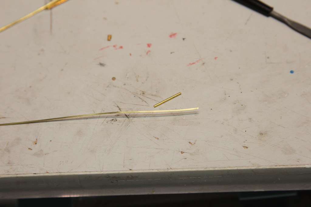
Stanchions first. I cut fourteen 1mm tubes and twenty eight 2mm tubes (two for each stanchion). The 1 mm tubes will insert into the 2mm tubes to create the wider portion at the bottom that then plugs into the railing. Another 2mm tube is soldered to the top of the stanchion as the eye through which the cable will pass. The top tube is soldered on larger, then filed down to be almost even with the stanchion, after which everything is blackened
Note: Trying to hold these things in place to be soldered took some ingenuity, extra clamp hands, and locking needle tweezers. During this process, more than a couple of these little escape artists went flinging across the room never to be seen again.
I soldered a ring on one end of the aforementioned cable and an eye bolt onto the other end. Here was a trick – I wanted to make sure all the stanchions lined up properly in terms of height, distance, etc – and then make sure the cable was the exact right length. I couldn’t just cut and tie it like a rope, so I had to pass the cable through the stanchions after they were mounted, measure the distance of the cable, then solder the eye bolt on the end of the cable while it was on the ship. Obviously paranoid about burning the ship up in a giant ball of polyurethane and wood flames, I used a piece of metal to block off everything that wasn’t being soldered. Very tense process – wish I’d have been able to take a photo of it whilst I was doing it.
The bow end of the railing is seized just as though it were a rope, and the waist end of the cable is mounted into the railing with the eyebolt. After writing this and seeing the photos – it comes across as a pretty simple process. However, it was quite complicated and very tricky to get correct and look realistic.
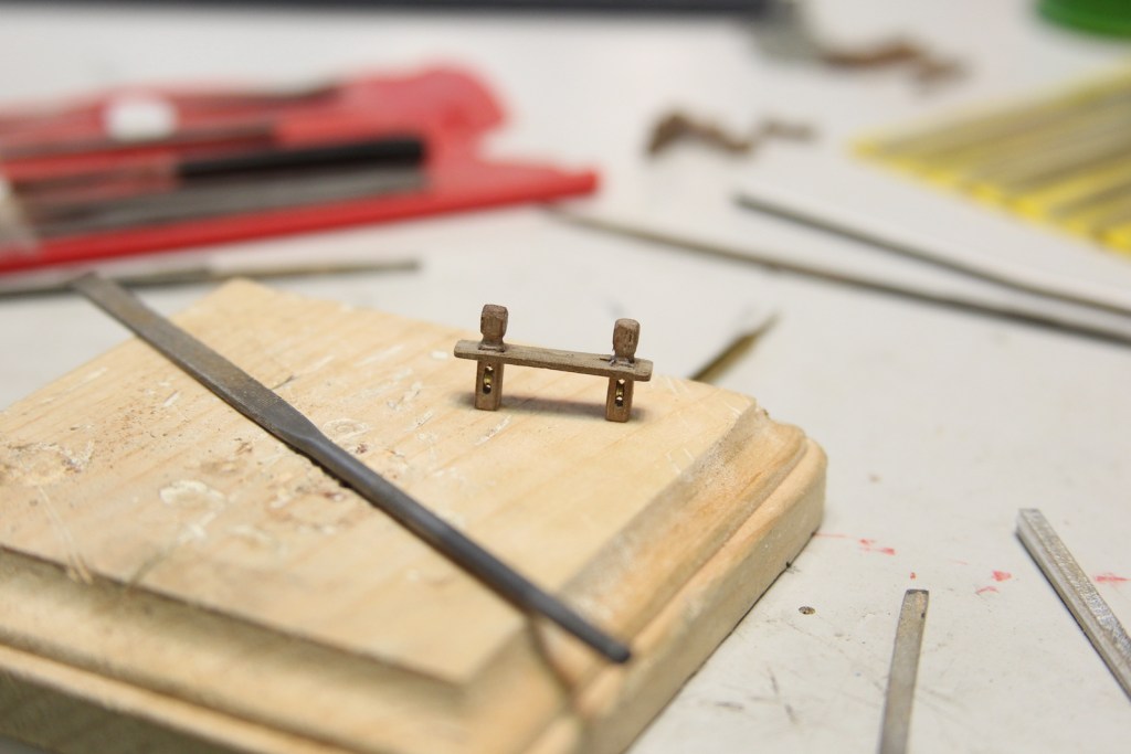
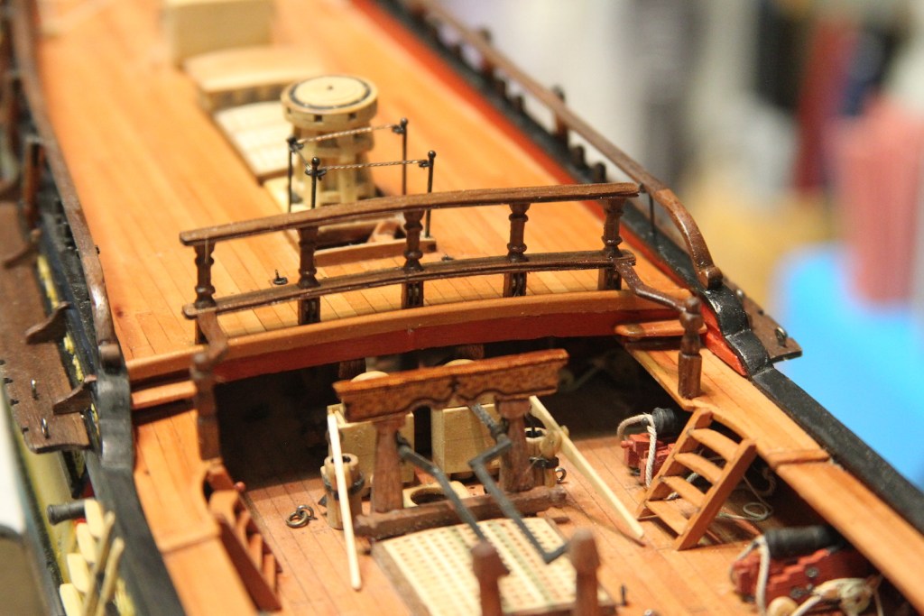
An interesting aspect of a ship from the age of sails is that pretty much any aspect of the main deck was fair game for seizing rope or otherwise tying off rigging lines. Most areas had belaying pin racks, rings, or cleats of some kind – but most railings also served as rigging opportunities. The forecastle railings to each side of the belfry as well as the quarterdeck railings – called the breastwork – were outfitted in such a way that they were as imminently functional as they were decorative.
I’ll preface by saying the railings and products that are supplied by Chris Watton’s kit are just fine in this regard – however, I’d already committed myself to using walnut for the other railings, bitts, crossbeams, etc. Once again, since I’m being sparse with paint, I want everything to match – or at least compliment.
Unfortunately walnut – though prevalent in my wood pile and nicely toned – is not the densest wood for carving which makes it difficult at such a small scale of 1/64. But it is pretty malleable for shaping, etc. I essentially worked on the forecastle and quarterdeck railings simultaneously, as both required turning the stanchions on the lathe and create the sheaves.
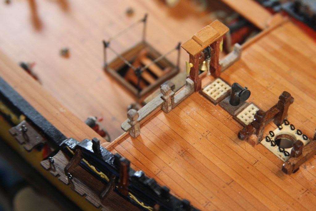
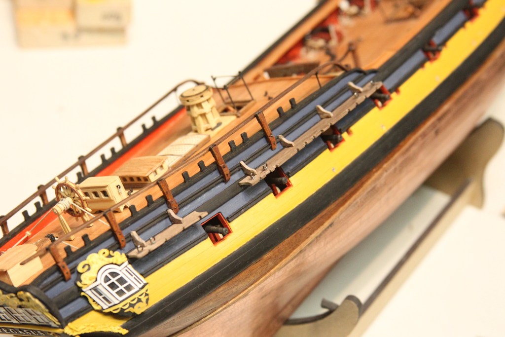
I started with the spar rack which serves as a ‘holder’ for the extra spars needed in case damage was incurred to the masts or yards. The extra spars were basically long poles laid across the waist and doubled as a support for the smaller launches (boats). While some kits have the spars lashed down the railing, the Swan class had these small racks – just a couple of pieces cut with a jig saw then sanded and shaped to fit the height of the Belfry stanchions just below the cleats. They’re the same width as the rails with the inside post shaped to fit snug against the belfry and the outside serving as a base for the railing.
I’ll preface by saying the railings and products that are supplied by Chris’ kit are just fine – however, I’d already committed myself to using walnut for the other railings, bitts, crossbeams, etc. Once again, since I’m being sparse with paint, I want everything to match – or at least compliment.
Unfortunately, we know that walnut – though prevalent in my wood pile – is not the densest wood for carving, but it is pretty malleable for shaping, etc. They’ll be two separate posts here, but I essentially worked on the forecastle and quarterdeck railings simultaneously, as both required turning the stanchions on the lathe and create the sheaves.
Forecastle
I started with the spar rack, just a couple of pieces cut with a jig saw then sanded and shaped to fit the height of the Belfry stanchions just below the cleats. They’re the same width as the rails with the inside post shaped to fit snug against the belfry and the outside serving as a base for the railing.
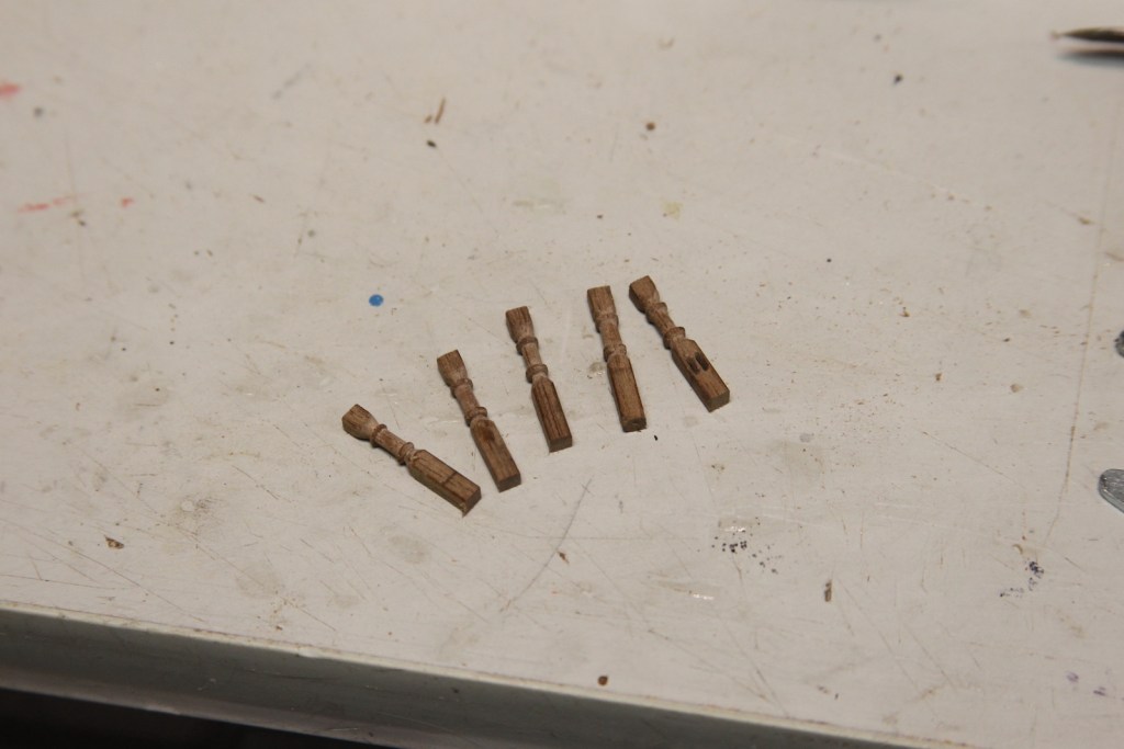
Stanchions are turned on the lathe with a little bit of decorative element. I had to keep it pretty simple because the walnut has a tendency to flake when cutting this precise. The first picture illustrates the several experiments it took using a variety of options before I found what worked for me and didn’t either flake off the post or snap it completely. My rather cheap carving tools are regularly sharpened on the belt sander before I use them. Essentially I use a file to get started, the carving tools to shape, and then a sanding stick to smooth out the edges.
After the difficulty making the tiny sheaves for the catheads and chestrees, I had totally convinced myself that it was fine to just make faux sheaves here; especially since they’re under railings and difficult to see. Then – for whatever masochistic reason – I decided that I should go ahead and make sheaves. As you might imagine it is completely torturous at 1/64. And yes – I am totally convinced this is going to bite me in the a** when it comes time to actually try and rig the thing. But, in the meantime, I think they ended up looking pretty good.
For the forecastle, I split the railing itself into two pieces (as shown above) to facilitate mounting it with the stanchions. This worked well, but required lots and lots of patient bit-at-a-time sanding to get everything line up properly and fit snug. You’ll see later that I took a different (and ultimately more tedious approach) on the quarterdeck breast work. Stanchions and railings are mounted after a lot of test fitting and tiny adjustments with a sanding stick. Then everything is sanded smooth to get as tight of a fitting as possible. Still a couple little gaps that get masked with the coat of tung oil that’s applied after everything is permanently in place.
Quarterdeck
The breastwork on the quarterdeck is pretty similar in terms of how it’s accomplished. First step is to turn the stanchions on the lathe. The tricky part (as I mentioned) is that these are double sheaved instead of single singled. I’ll tell you, at 1/64 that’s a real bear. The actual metal sheave needs to be so thin (less than .5mm) that there was just no real way I could notch it small enough – so I gave up on that and settled for just having the ring in the slot – so to speak. Creating the slot started with drilling holes in line, then picking them out gently with a #11 scalpel as much as I could. Next, I shaved down my smallest needle file to almost paper thin so that the grooves were only on one side and one edge. Finally, I gently filed out each groove a tiny bit at a time.
The sheaves are cut from a 2mm metal tube filed down on each side until they fit into the slot. The slot determined the size of the ring, not the other way around. File – test fit – file – test fit, etc. Here’s a progression of what that looked like. Each stanchion took almost 90 minutes to get cut and grooved out. Sorry, the focus isn’t great on these two. Probably because I was cross-eyed from filing out the grooves.
I took a different approach for the railing this time – instead of two pieces, I measured out a single piece with about .5mm overlap on each side of the stanchion and cut square holes to fit – starting with drilling out a hole then filing with a square edge needle file. This took much longer than the ‘two piece’ method, but eliminated the very slight line you can see in the forecastle railing. The edges of the railings were scraped for a little decoration.
Gluing it all together was a trick. And yes – I noticed the middle stanchion was crooked upon taking the photo (ah, the joys of macro) and fixed it.
The railing is mounted on the deck and follows the shape of the deck. Good thing I had to fix that middle stanchion, because after the railing is placed on the deck, the bottom rail sits a fraction higher on the middle post. It was helpful to dampen the railings as I fit it to the deck – even so I was anxiously anticipating the whole thing to crack as I bent it. I also added a pin in the middle stanchion as I affixed it to the deck to hold the structure it in place while I clamped it down.
The railings are extended to the gangways with two more stanchions and extended railings with an “S” curve to them. The stanchions are turned on the lathe with a little round newel post top. The railings are cut from a single block of Walnut. I cut them out with the jigsaw together to ensure that they mirror one another, then after the shape is sanded I split them into two railings on the Byrnes saw.
From there it’s the fit-sand-fit process until it’s snug. After everything is fitted and glued, the edges are all gently sanded and smoothed out and the whole thing is given the Tung oil treatment. Overall, I’m pretty stoked with how this turned out – especially at 1/64.
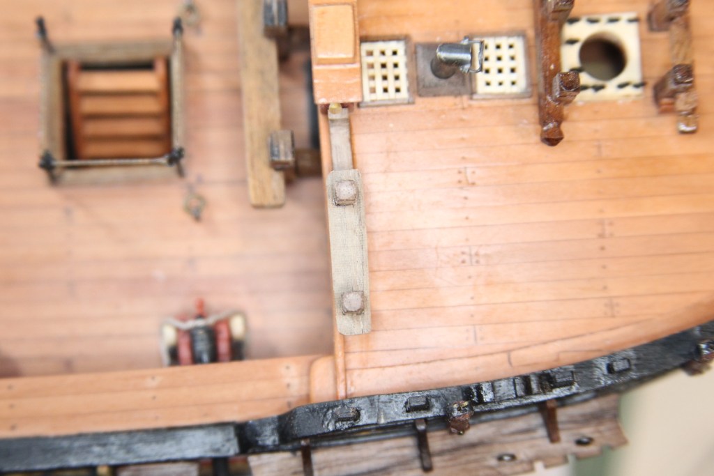
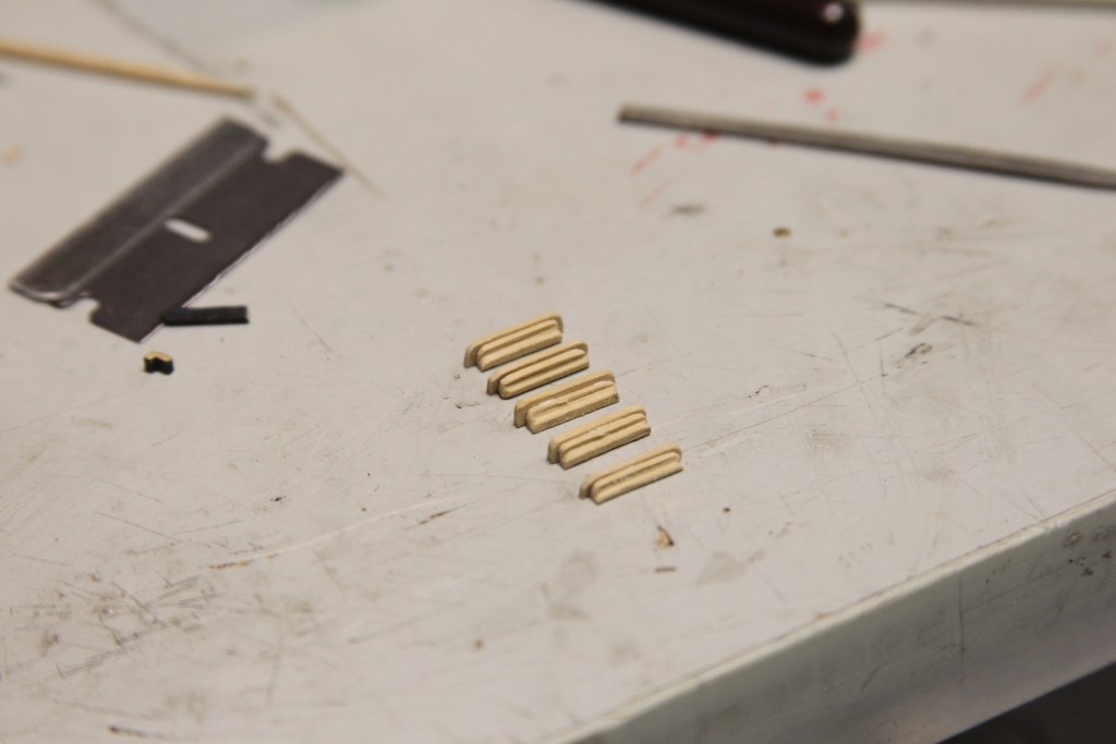
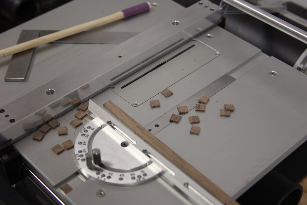
There are a couple of other fixtures along the hull of the ship that are pretty straightforward but require specific attention. The steps (ladders) provide access to the deck (of course) and extend from the waist to the waterline. The Fenders are just strips of decorated wood next to the steps that protect the hull as barrels and other supplies are hauled aboard. The chesstrees serve as a sheave connecting rigging to the insight of the gun ports.
The steps are made from two separate pieces of boxwood fit together to create a decorative element. The smaller of the two pieces is cut with a scraper then glued to the ‘step’ portion. Each step is mounted to the side of the hull with the middle one cut out to provide for the scupper opening next to the gunport. The bottom two are painted black to match the main wales.
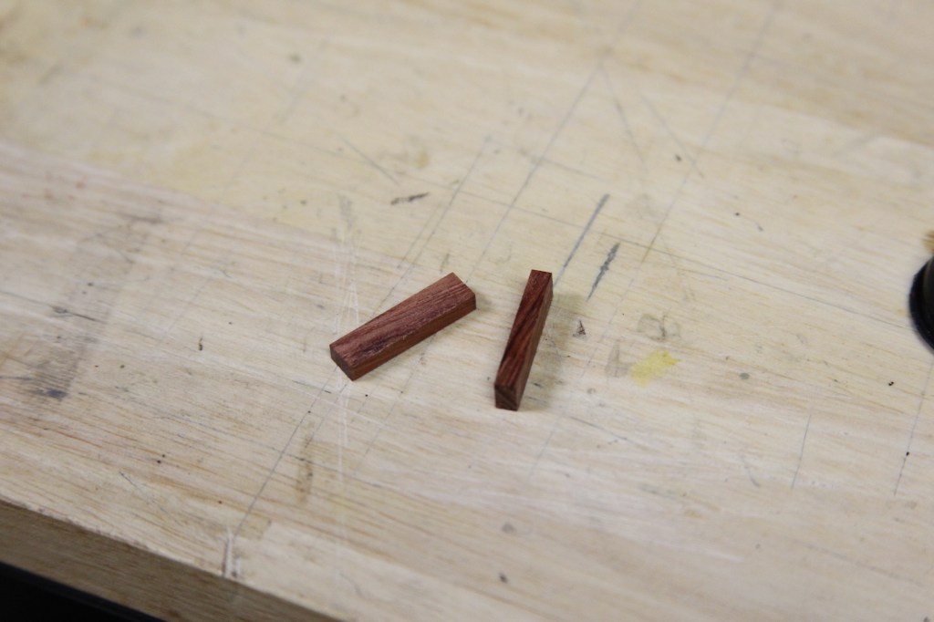
You can also see the fenders in the above photo. A simple affair, the fenders are strips of boxwood cut with a scraper to provide decoration then mounted in chiseled out areas of the sheer strake and drift rail. The chesstrees are a bit more complicated. Also cut from boxwood, they are specifically shaped – thin at the bottoms but wider at the top to facilitate a sheave. I created these pulleys in the same way as the Catheads – a cut piece of notched brass inserted into a filed out hole.
The chesstrees are mounted just aft of the fixed blocks in the gun ports. Later, a rope will extend from the yards, through the chesstrees and into the fixed blocks. The chesstrees serve to lessen the tension and wear and tear from that rigging.
The word “frieze” means any kind of horizontal band of sculpted or painted decoration. It’s very common along the ceilings and walls of historic buildings dating back hundreds, if not thousands of years. From an anthropological perspective, it provides interesting insight into the cultures of the time. Like many of the HMS ships of the 18th century, the frieze work on the Pegasus is predominantly mythological and quite intricate. While the frieze on quarter galleries and transom is mostly carved (see the transom post here), the frieze along the gun ports was painted while in port and often didn’t last very long – washing off once under sail. There are a couple different methods of applying the frieze on models; some are printed on thin paper and applied to the hull while others paint from scratch. Yet other kits (as with the Peg) have photo-etched pieces that are painted then glued to the ship. While the photo etching allows for great precision, it is often difficult to get them to look authentic. Here’s who I tried to achieve that.
First, I airbrush painted the photo etched pieces with a white layer and then yellow ochre to try and give the decorations some depth.
According to the plans provided (and the way the photo etched pieces are laid out) they are intended to be applied along the gun ports in 2 or 3 long strips. However, the byproduct of having done some things that added accuracy to the build is that those pieces will no longer fit as single pieces. Most notably, I’ve added the knee supports to the channels which cuts the gun ports into segments. I also have a wider ‘sheer strake’ that runs along the top of the gun ports which means less space in the areas for the frieze. Finally, the decorative drift rails along the gun ports is also a different size, once again making the area for the frieze narrower. My solution to all this was similar to my transom work. I cut the photo etched pieces into smaller segments and placed them individually.
The next trick is to get the frieze to actually look painted on rather than just airbrushed photo etching. To achieve this I provided depth by painting a yellow-ochre & gold darker shadowing along the bottom of all the decorations and then a highlighted touch of very light white & yellow ochre mix along the tops. As you might imagine, this required some magnification as well as a very small brush.
Final touch is a coat of wipe on polyurethane giving it all a protective coating.
The channels are planks of wood that form a ledge along the sides of the hull and house the “dead eyes” and form the base of the shrouds and ratlines; which in turn stabilize all the masts and form the bulk of the standing rigging. Yup – it’s all pretty complicated. But in short, the channels need to be level, consistent with one another, and firmly mounted against the sides of the ship. The kit provided some decent pre-cut and shaped channels that are relatively easily mounted. I stained the pre-cut channels to more closely match the color scheme I’ve been going with. The technique is to insert pins in the edges that are used to keep them firmly in place.
Things were going along fine – until I over sanded the edge of one of the channels trying to get it to fit snuggly against the sheer strake on the ship. Not only did I mess up the shape – but I made the channel too narrow. Problem is – they all have to match one another, and since I’m staining and not painting them them, that meant I had to re-cut ALL of the channels not just the one I botched. Using the patterns of the pre-cut ones, I re-cut all the channels using walnut.
Using the technique mentioned above, the channels are all mounted along the top edge of the sheer strake.
Once again, the channels serve as the foundation for the standing rigging – which is an enormous amount of tension. So it is vital that the channels hold their position, particularly if and when the ship goes through rough sailing. As such, the channels are held in place by “knees” or braces along the top. Interestingly, the plans do not account for these parts. Since they are such vital aspects of the channels, I felt it was a disservice not to include them. They are cut and shaped from the same walnut as the channels and mounted by cutting notches along the decorative drift rail. Side note: This also gives me a chance for a gratuitous picture of my snazzy miniature table saw from Jim Byrnes at Model Machines LLC.
Once all the channels and knees are in place, I’ll wipe it all down with Tung oil then begin the process of lining up the decorative frieze works.
The quarterdeck railings, also called the “roughtree rail” is fitted and bolted to the swivel gun mounts and runs the length of the quarterdeck. The fore end curls down in a decorative swerve and mounts to the main rail and ends in mid air at the aft just short of the transom. The rail itself is pretty basic and cut from a 3mm strip of walnut. The trick is getting the decorative end to look smooth and still match the rest of the railing.
The stanchions that hold the rail near the waist are made from a 1mm brass rod turned and shaved down to create a thin post with a thicker base. The cradle for the top is a 1mm brass strip cut & soldered on.
The ‘curvy’ end of the railing is drawn out and cut from a 10mm x 10mm walnut chunk on scroll saw. Lots of shaping and sanding to get the curvature first, then the chunk is cut down the middle with the table saw. I did it this way so I had a better chance of getting the two railing ends to look identical.
The end of the railing and decorative ends are both notched to create a strong joint that is also (hopefully) minimally noticeable. A little more shaping took place after it’s all lined up so that the railing and the end match up in both thickness and width, then the whole thing is mounted and given a coat of tung oil.
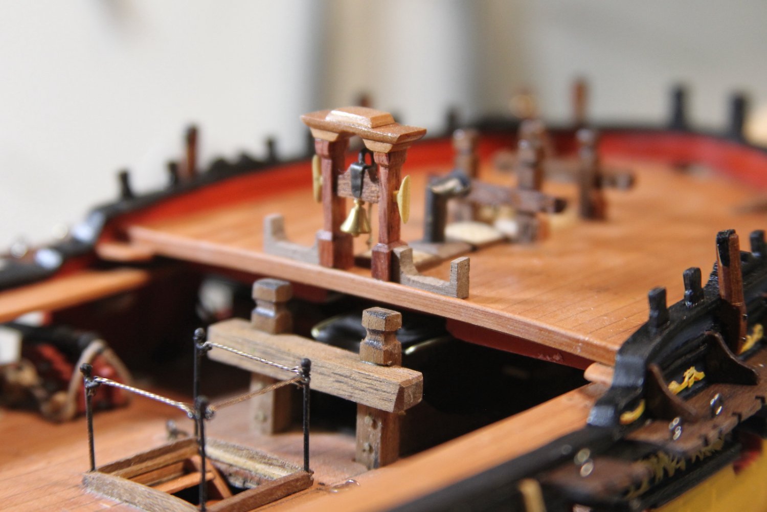
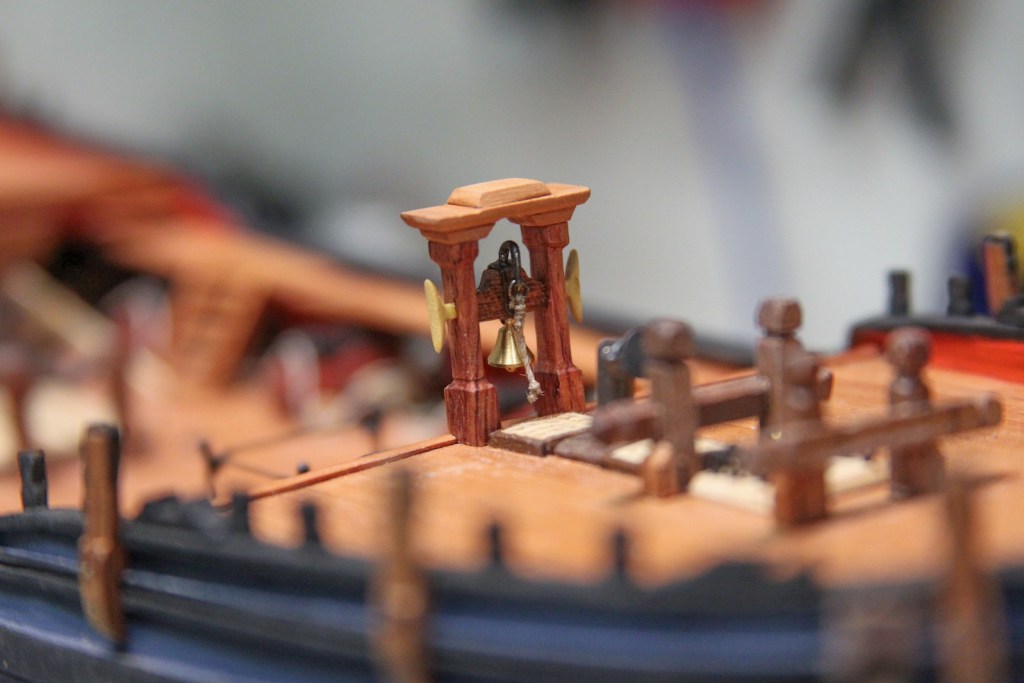
I’ve had something pretty specific in mind for the Belfry for quite a while, and of course I’ve been stalking Dan’s Vulture (here’s his belfry). A few years ago I received a couple of pens as a gift from a charity auction, and they came in this snazzy pen case. I’ve been looking for a reason to use the wood on these end pieces, but needed my recently purchased miniature table saw to get a good cut on this really dense wood.
I cut two 5x5mm pieces to serve as the stanchions, and three pieces of Swiss Pear scrap for the roof and shaped/sanded it all. Really, one of the down sides to having the new saw is that I’m half tempted to go back and re-accomplish half the stuff I did by hand.
For the bell housing, I used a walnut piece, and created a brass bracket to hold the handle. The handle is a shaved down piece of brass rod that fits into the bracket and bends over to hold the rope. Finally, I outfitted two boxwood cleats instead of metal – which I thought was an aesthetically pleasing and acceptable substitution.
The whole thing put together and mounted. To me, the Belfry was another opportunity to add a little bit of artistic flair.
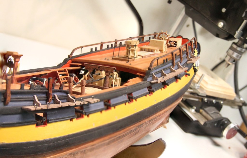
In addition to the 6-pounders along the deck, the Pegasus also had an addition 16 swivel mounts for 1/2 pound falconet guns along the railings on both the forecastle and quarterdeck. Although it was more likely that there were about 8 to 10 guns that were switched along the mounts when needed, it’s much more fun (of course) to fill all the mounts.
I started cutting and shaping the swivel gun mounts out of 3mm x 3mm mahogany that I have lying around. Although several plans call for them to be painted black, I don’t really want to paint them – I want them to stand out a little bit but compliment the rest of the subdued color scheme I have going. I shaped them based on FFM with the octagonal top and sized to fit my ‘scale guy’ once mounted. Each mount has a small bracket to in which the gun is secured and is bolted to the side of the ship.
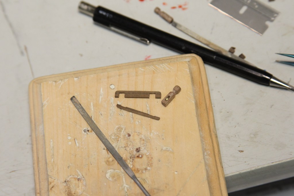
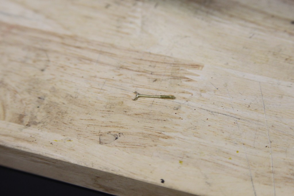
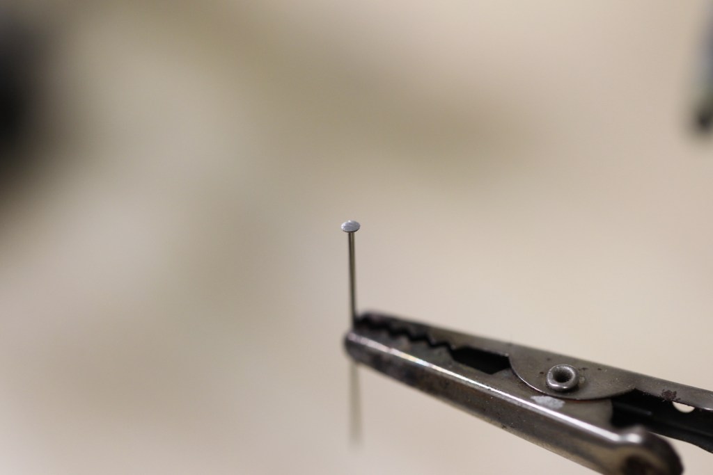
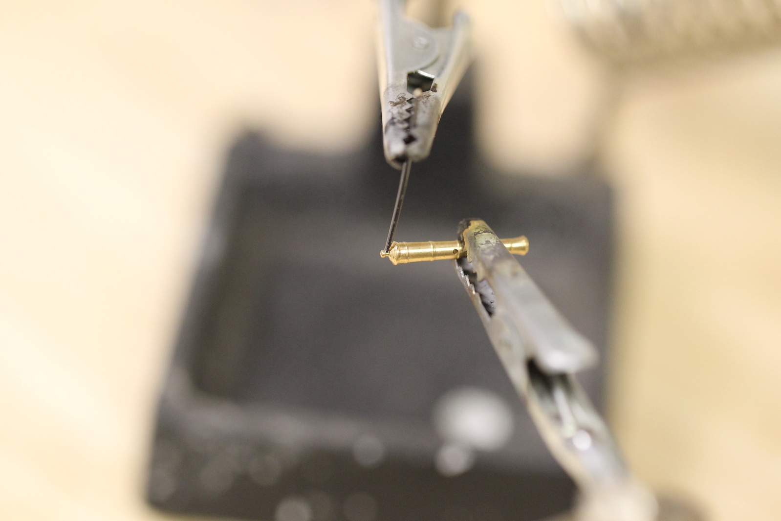
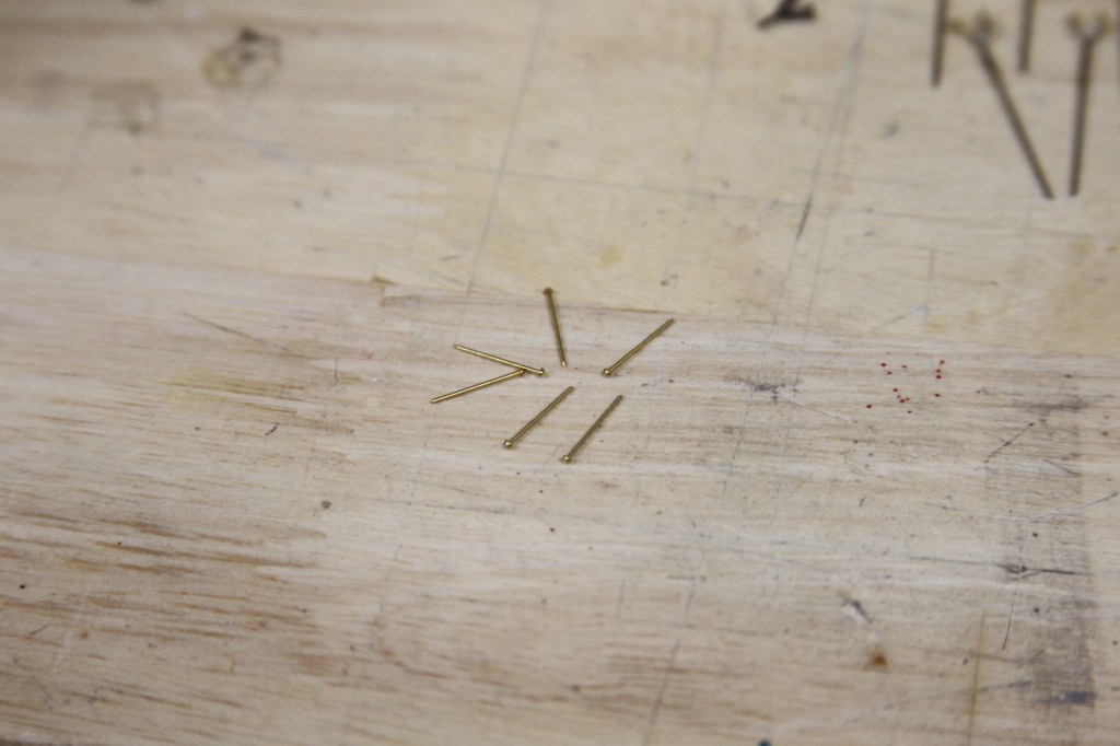
The guns sit upon these swivels in a small bracket that allows them to be moved up and down as well as back and forth. These small brackets were created out of brass strips that are shaped, then drilled out on the sides. I used pins with shaved down pin heads as the base of the mount. The “small as a pin head” idea also provides an idea of just how small of a scale we’re working with here.
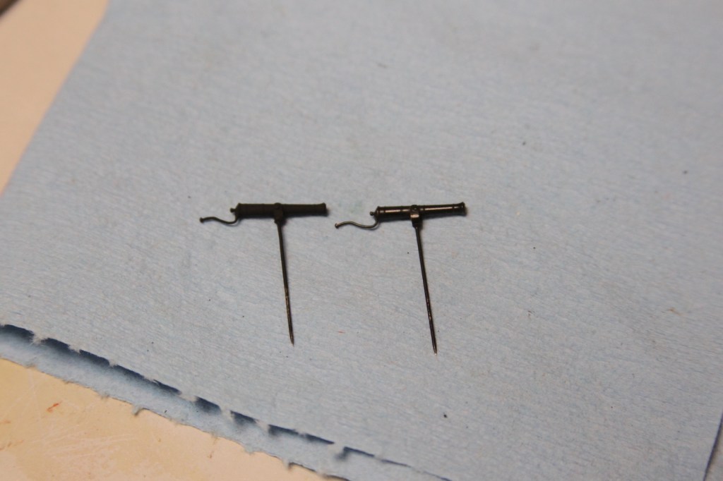
The side by side comparison between the pre-fab swivel guns and the 1/2 pound brass cannons I purchased from Syren Model Company show some key differences. However, One of things that is accurate about the kit guns is the way in which the rear handle extends back.
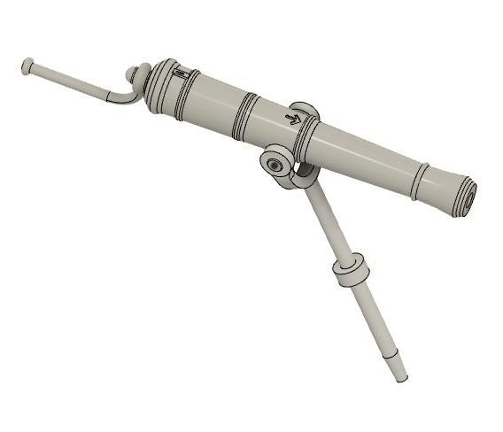
I briefly considered hacking off the breach button from the brass one and trying to extend a handle back – but quickly realized this was beyond my capabilities without the entire thing looking like crap. So I opted for the secondary style that you also see around that time frame in which the handle extends from the rear of the gun. This deviates some in terms of the Peg’s guns, but it’s what I think I can achieve. Here’s a good CAD representation from a fellow builder.
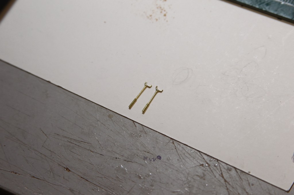
After a lot of attempts at trying to get the handle to “loop” around the button as shown in the illustration, it was just too small of a scale and everything I did once again looked like crap. My first working attempt was to try and mount/solder it to the bottom of the gun instead.
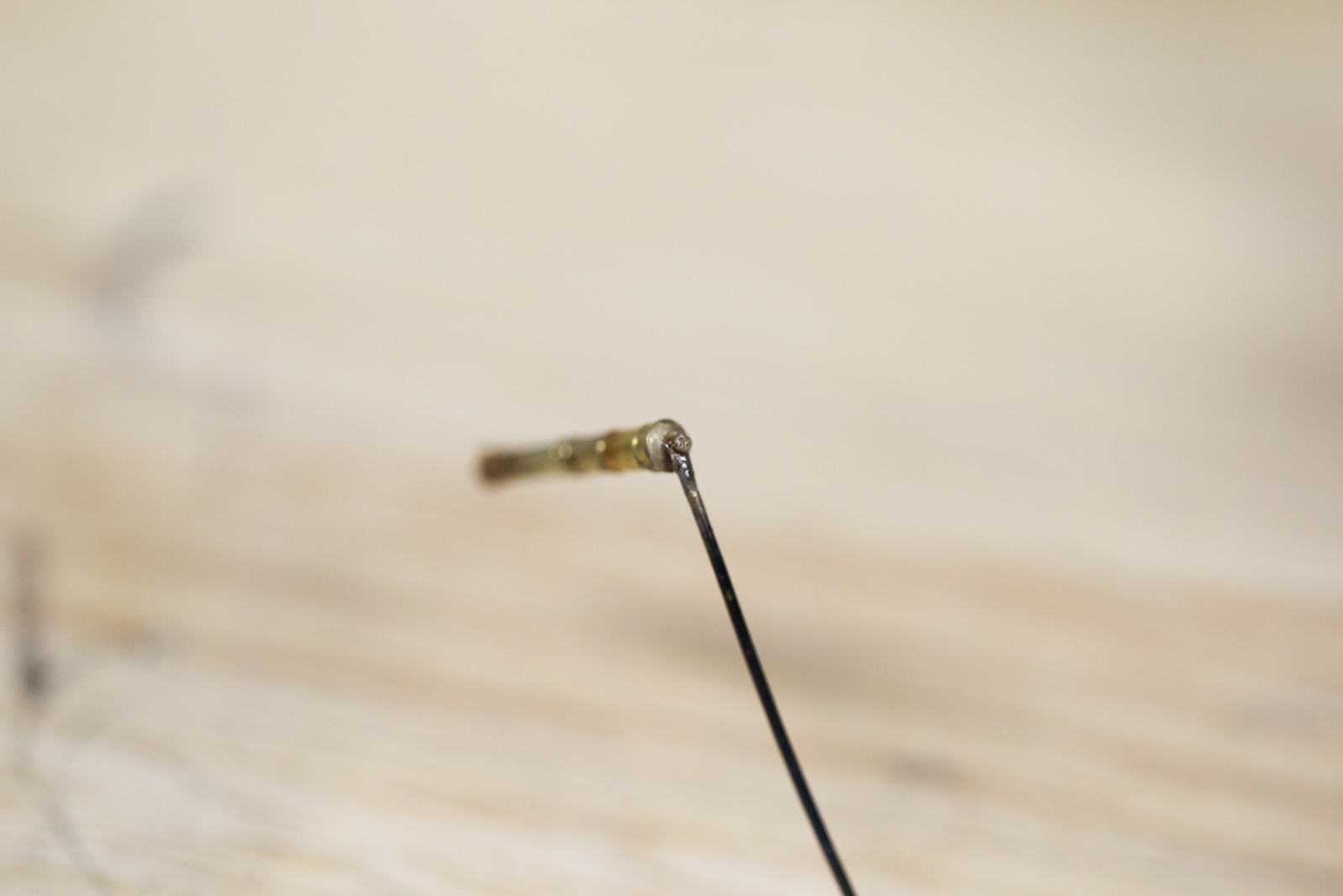
At first, I felt like this was acceptable. Mostly since at the end of the day, the combination of the very small scale and the bottom of the gun not being visible made this passable. Then, of course the more I looked at it the more annoyed with it I got. So I tried again – this time, taking the wire handle, flattening the end, and cutting a small groove in the end with the smallest cut pin file I could find. That groove allowed me to solder it to the rear of the gun and kind of “simulate” the loop over the button.
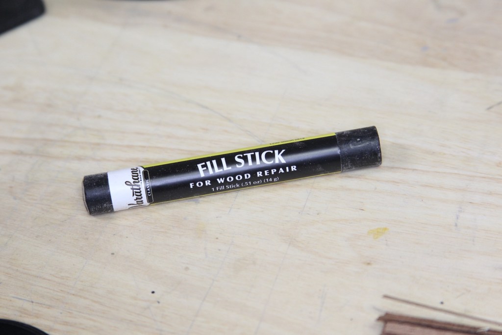
Following the idea of my hatch railing stanchion tops, I created the “knob” at the end of the handle by taking a small amount of this ebony wood filler and rolling it into a ball.
Still have to work on getting the size acceptable, so I’m not sold on this technique. I blackened the cannon to get an idea of the end result. The “ball” is way out of scale, and I still needed to do some work on my blackening techniques, and I’m not thrilled with this as a final result – but gives me some idea of how these guns will look once mounted.
After a couple of days of contemplating how to get this handle right, I eventually though of the ever handy .020″ mico-mark tiny nails that I’d used on the rudder (and here on the brackets). So why not take another run at the guns using the longer version of those? This got me much closer to what I wanted – as the handles themselves are more to scale with the guns.
It was a real trick soldering them however – as the melting point of the little brass nails was almost exactly that of my softest silver solder. So often the nail would melt a little along with the solder and had to be fiddled with. Then I shaped the handle after it was cooled. About 1/3 of the time, shaping the handle also meant snapping it off and starting over.
Blackening Techniques
Like many folks, my success with blackening has been hit or miss, and I always ended up having to do touchups or over-weathering to make up for the inconsistencies. But with the success I had soldering the swivel guns, and how inevitably visible they are – I wanted to get the just right. So I went back to the basics on blackening by doing some research on the Model Ship World forum and following Greg Herbert great tutorial post “Blackening Revisited” with all the steps. Ordered some Sparex acid solution, stole my wife’s crockpot warmer, and set up my station.
Essentially the process is – ‘pickle’ the metal in the acid solution for 10-15 minutes, denature it in a baking soda solution, sanitize it completely in a bath of acetone for another 10-15 minutes, let it dry completely, chemically blacken it with diluted a “Brass Black” product, then finally, polish very lightly.
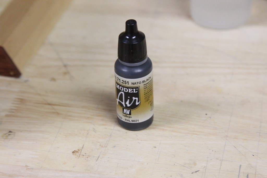
After blackening, all the guns are mounted into their brackets, then some final weather takes place. Each cannon gets a shot of Vallejo brand “Nato Black” from a light air brush, polished once again, then dusted with Tamiya’s ‘rust’ weathering product.
I’m pleased overall with the final product. The guns themselves will be mounted permanently much later in the build – as to avoid me ripping them off with a snagged sleeve or other such clumsiness. But, I couldn’t resist mounting one of the guns to get an idea of how they’d look.