The mast tops are the elevated platforms above each mast at the mast cap and provide space for lookouts, assist in navigation, and to access upper parts of a ship’s rigging. Many folks may have heard mast tops (especially those highest on the ship) referred to as the “crow’s nest.” The mast tops for the Pegasus are planked wood structures with railings on one end and able to fit nicely over the mastheads and shroud rigging. Mast tops also provide room for additional rigging including a number of blocks and collars that serve as an intersection for much of the standing and especially running rigging. Many contemporary models provide for a ‘scaled down’ version of this rigging because it becomes quite complicated quite quickly. My goal – as with the rest of this build – is to provide as much accuracy as possible within the confines of the small scale.
The kit provides a very basic version of the mast top that has been simplified for most modelers. It isn’t quite accurate in a few ways, but serves as a good starting point upon which to build mast tops that are more accurate and pleasing. The first thing we notice is that the center square opening contains an addition notch in it. David Antscherl’s The Fully Framed Model suggests that this notch began in about 1775 and allows for lower yard slings to pass through the mast top more easily. However, according to James Lees The Masting and Rigging of English Ships of War, 1625-1860, this practice didn’t begin until 1802. Lees says up until that time, two additional holes were cut on either side of the center near the front of the mast top to accommodate these slings. While I’ve been leaning toward the TFFM for most of this build, I’m not keen on how much I can see the cross trees through the notch, so I’ll going to square it off.
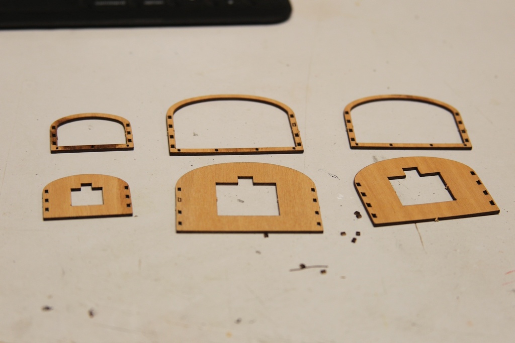

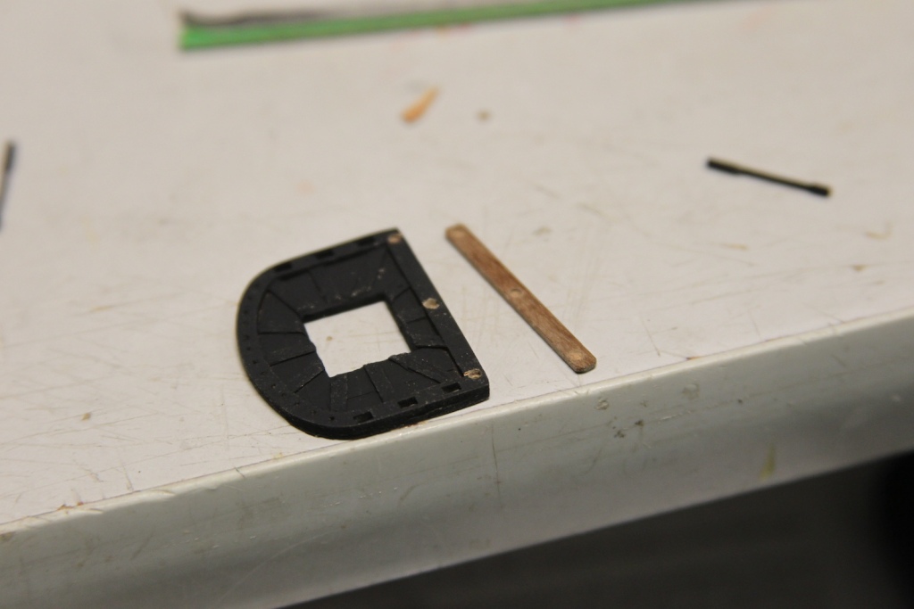
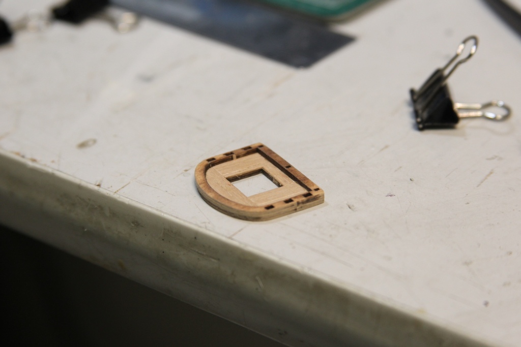
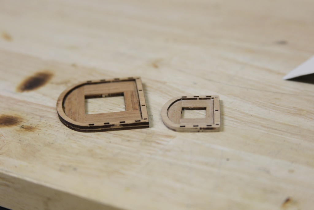
Step one is to plank the base of the mast tops. For this I’m using .6mm x 3mm planks that were originally intended for the deck; which we’ll remember I replaced with pear strips. This planking squares off the aforementioned notch. After some light sanding I cut/sanded out room around the perimeter to attach the rim. The overall mast top is much too thick and out of scale at this point, so I sand the entire thing down both top and bottom. The photo below shows the difference in thickness between the sanded down mizzen top and the un-sanded fore top.


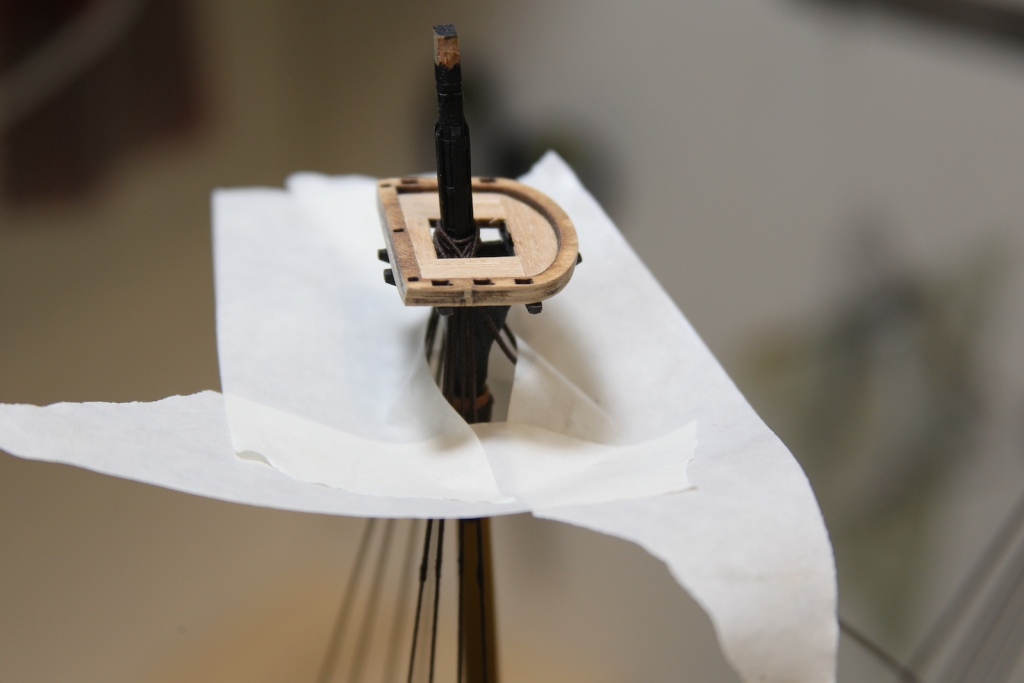
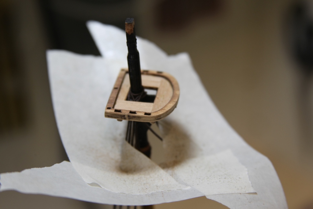
I’ve also run into another small problem – the mizzen top mast is a bit too small for the cross trees and trestle trees that I’ve already installed on the mast. This isn’t a huge challenge, I’ll just need to sand them down a bit – however, I don’t want all that sawdust to get on the ship. To help with that, I put a masking tape “bib” on the mast to catch my shavings as I sand it down.

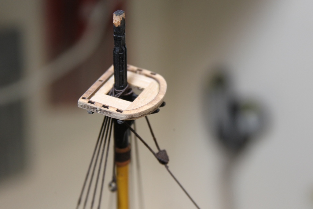
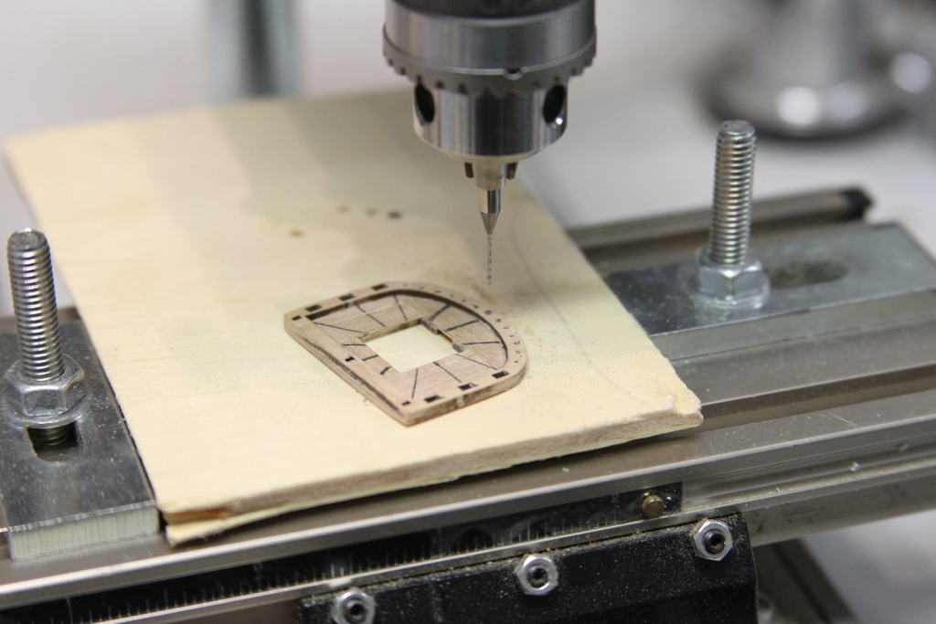
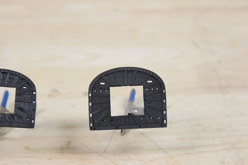
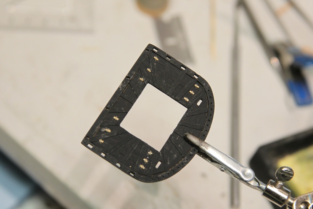
Another aspect of the mast tops on predominantly English ships of the era were crow’s feet. The crow’s feet were an assemblage of small cords extending from the front of the mast top to the through the “euphroes” and then attach to the main stay to extend the awnings and keep the foot of the top sail from striking under the tops or other areas of rigging. The crow’s feet run through a series of small holes on the rim of the mast top – the number of holes depend upon the size of the mast top. There are some different accounts of the number of crow’s feet depending on which publication reference. While I took these into account, I ultimately went my own path here and decided on a number of holes based on visual aesthetics and measurements. I decided that using .10mm line and drilling the smallest hole that would accommodate that line meant spacing each hole about 2.5mm apart. Given that spacing – I ended up with 13 mizzen holes and 21 holes for both the main and foremasts. I measured out these holes along with the locations of the small timber support battens, the holes for the deadeyes and futtocks shrouds, as well as the holes for the blocks mounted under the mast top.


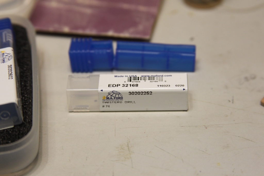
The crows feet holes were started with a dental pick before being drilled out. The little indentation provides a seat for the drill bit when the drill press is lowered and keeps the bit from sliding and missing the location at the start of the drilling process. I have a lovely set of MA Ford twisted drill bits that work brilliantly, avoid slipping, and give me very clean holes at very small diameters. The #74 bit is about .5 mm, which gives me a smooth feed of the line.
After all the crow’s feet holes are drilled, the support battens are added using .6mm x 2mm strips. The block mounting holes and holes for the aforementioned holes for the slings are added before they are all painted black to match the mast head.


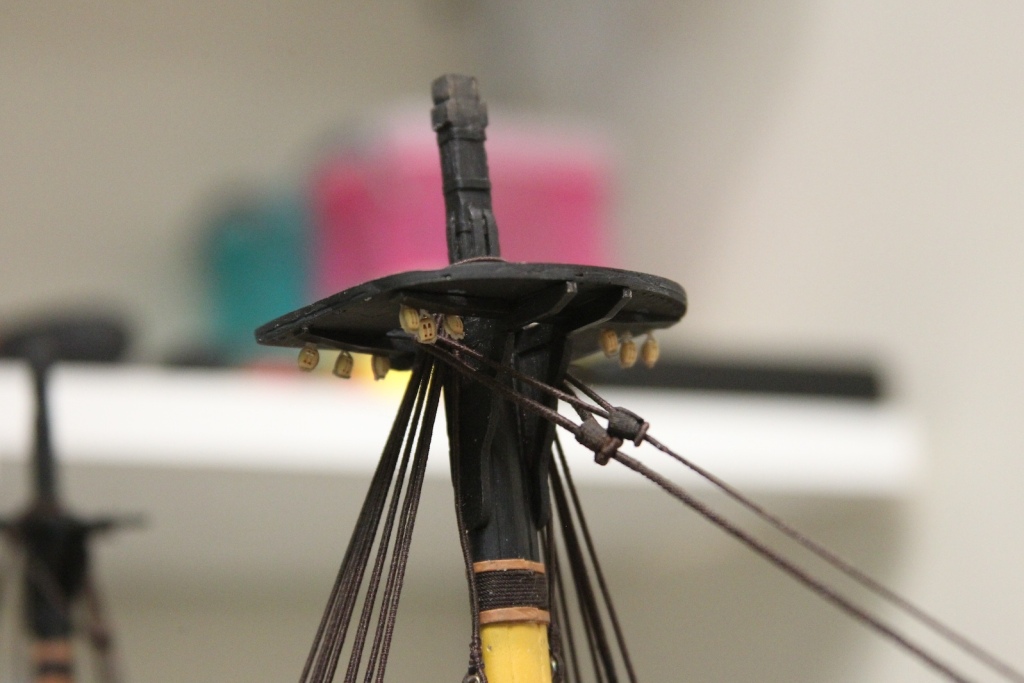
As mentioned above, the mast tops not only serve as a lookout and stable platform for sailors to reach upper rigging, but they also serve as a focal point for much of that rigging. There is a significant number of blocks and tackle that attach or go through the tops. A series of 12 double blocks beneath each of the main and fore mast tops handle brace lines, bunt lines, and leech lines (all of which will be explained later). There are some variations to the number and sizes of these blocks, but as with much of this build, I’m predominantly following the guidance in The Fully Framed Model by David Antscherl while referencing others. Technically, these sets of blocks under the tops are also slightly different sizes – from 8″ on the outer blocks to 6″ inches on the inner blocks – however this differences ends up being pretty inconsequential at this scale, so I’m using 3mm blocks throughout. I did however pre-drill the holes in the blocks to be slightly larger to ease the rigging and accommodate larger lines if necessary.
Most model instructions and model builders themselves typically mount these blocks to the bottoms of the mast tops by using eye bolts. This is bar far the easiest method and thus the most common. However, in reality these blocks were mounted using small wooden pegs to hold a loop in place after it’s been inserted into the mast top. This is what I’ll be doing to add a nice touch of realism. However, since these blocks are all under the tops and will be very difficult to see once the rigging is complete, I am taking a couple of other shortcuts that will hopefully be unnoticeable to most people.
First, to simulate ‘seizing’ of the strop around the block I used a simple overhand knot rather than a full wrapping. Second, I secured the bottom of the strop by just overlapping and adding a touch of CA glue. I pre-stropped all 24 needed blocks before moving on to mounting them. I wasn’t quite as consistent as I would have liked getting all the eye loops exactly the same size, but came as close as I could.
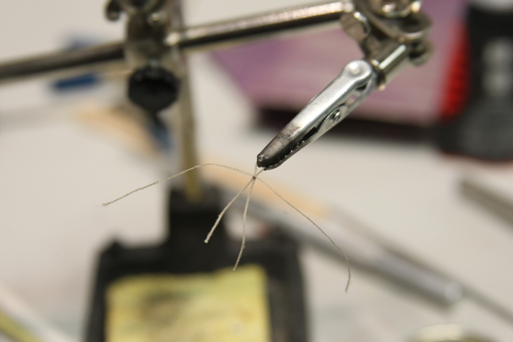
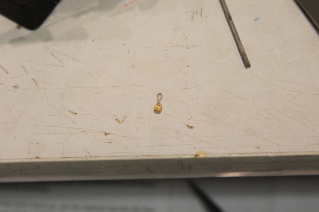
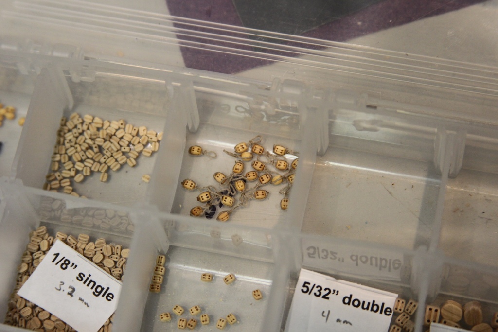
The small peg that holds the block to the mast top was quite small at this scale and very fiddly to make. I started by sanding down a bamboo toothpick to as narrow a diameter as I could get. Bamboo toothpicks are very good to have on hand as they are firm enough to be cut down for a variety of uses. I ended up getting it down to just under 1mm before it would just shatter or fall apart.


I used a fishing line to feed the eye loop at the top of the block through the hole in the mast top, then insert the peg – a 1.5mm sliver cut off the end of the shaved down bamboo shaft. A touch of white glue is used to hold it in place.


Once all 12 blocks are mounted, the mast top is test fitted on the mast to ensure that none of the blocks interfere with the cross trees and trestle trees upon with the top sits. If any of the blocks are too close or fitted too tightly, it has the potential to foul the future rigging.
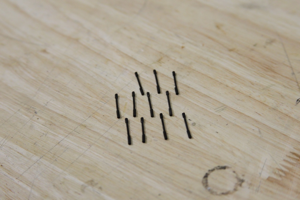
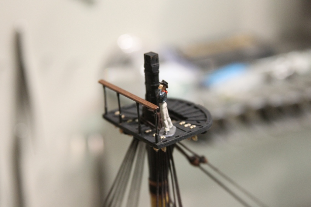
The final step for the mast top are the stanchions and railings. Each mast top features one railing on the aft side of the top. I wanted these railings to match those on the main part of the ship, so I am again using brass tubing and a walnut strip. The stanchions are three parts – the main post is a 1mm brass tube cut to 15mm with each end sanded to a point to facilitate my later placement and soldering. The bottom of the stanchion is 2mm tubing cut to 5mm and the top is 2mm tubing cut to 3mm (missed taking a shot of these). The bottoms and tops are slid over the top of the pointy ends of the middle and silver soldered into place.
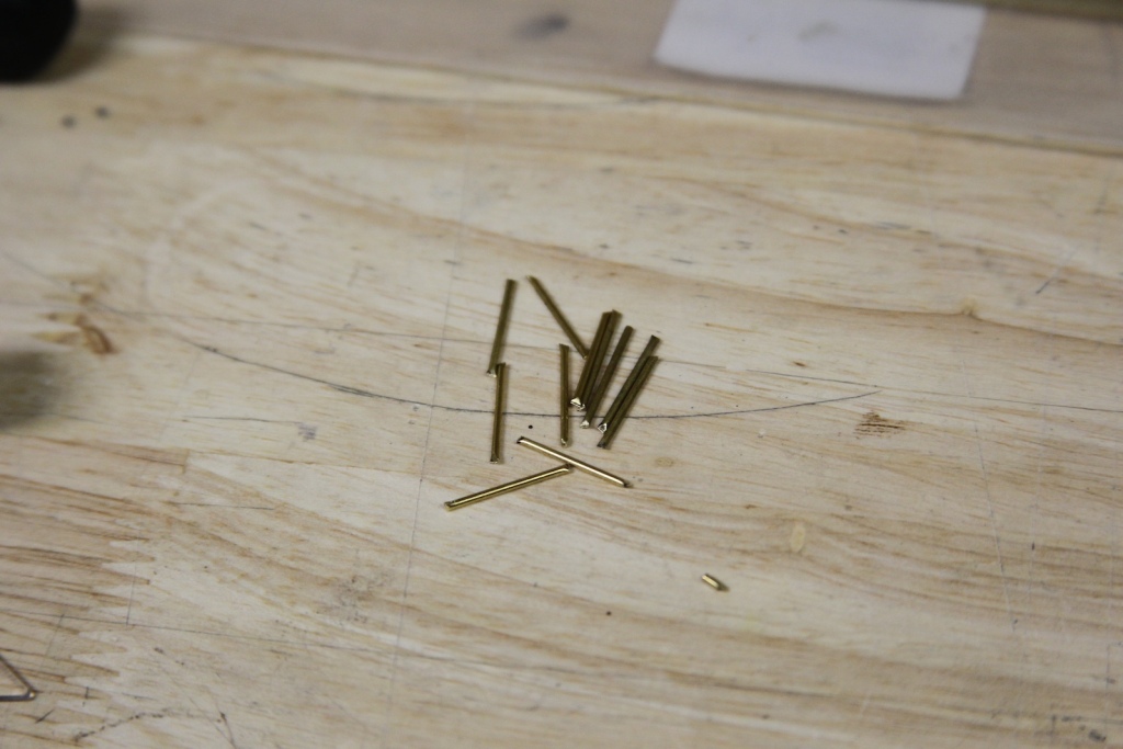

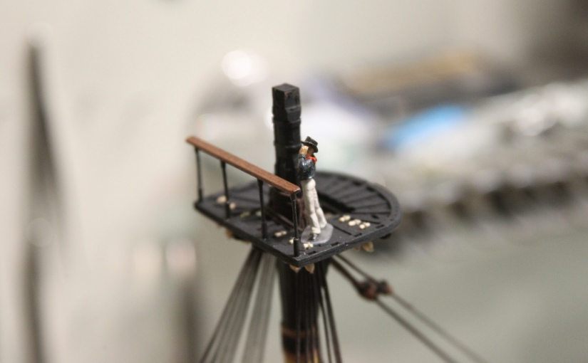
The stanchions are sanded and blackened. The blackening process is laid out in my previous section regarding the Swivel Guns. I bored out recesses in the mast tops and the under side of the railings to fit the stanchions then assembled them. The last step is a thin coat of tung oil on the railing. The first mate let’s me know that the sizing and scaling are pretty close to what I’m looking for.
